"06" December 2022
SWITCHING CHARACTERISTICS VAC DIAGRAM
The principle of operation of a diode is its ability to pass current in a certain direction.
The design of the diode implies the presence of two zones in it:
- anode “+”;
- cathode "-".
According to the physical principles underlying the operation of diodes, they can be divided into:
- semiconductor;
- vacuum
For the first type, the working medium is a semiconductor material with various additives, for example, silicon or germanium.
In vacuum, the current arises due to the emission of electrons from the cathode; all processes occur, excuse the tautology, in a vacuum. Currently, semiconductor diodes are used almost everywhere.
The design and principle of operation will be discussed using the example of a rectifying diode (there are other types, but this one is more common).
Designation of a semiconductor diode (Fig. 1a).
The anode in the diagram is conventionally designated by a triangle, the cathode by a transverse line passing through the top and parallel to the base.
The designation itself can suggest the connection order: the triangle’s apex faces in the direction of the forward current. The direction of the current is usually considered from “plus” to “minus”.
What is a diode
A semiconductor diode or simply a diode is a radio element that allows electric current to pass in only one direction and blocks its passage in the other direction. In a hydraulic analogy, a diode can be compared to a check valve: a device that allows fluid to flow in only one direction.
check valve
A diode is a radio element with two terminals. Some diodes look almost the same as resistors:
And some look a little different:
There are also SMD versions of diodes:
The terminals of the diode are called anode and cathode . Some people mistakenly call them “plus” and “minus”. This is not true. You can't say that.
In the diagrams the diode is designated as follows
It can only pass electric current from the anode to the cathode.
Direct diode connection
We change the polarity of the power source - plus to the anode, minus to the cathode. In this position, a repulsive force arises between charges of the same polarity. Negatively charged electrons move away from the negative and move towards the pn junction. In turn, positively charged holes are repelled from the plus and are directed towards the electrons. The PN junction is enriched with charged particles of different polarities, between which an electric field arises - the internal electric field of the PN junction. Under its influence, electrons begin to drift to the P side. Some of them recombine with holes (fill the place in the atoms where there is not enough electron). The remaining electrons rush to the positive side of the battery. ID current flowed through the diode.
To avoid confusion, let me remind you that the direction of current in electrical circuits is opposite to the direction of electron flow.
What does a diode consist of?
In our world there are substances that perfectly conduct electric current. This mainly includes metals, for example, silver, copper, aluminum, gold and so on. Such substances are called conductors. There are substances that conduct electricity very poorly - porcelain, plastics, glass, and so on. They are called dielectrics or insulators. Between conductors and dielectrics are semiconductors . These are mainly germanium and silicon.
Once germanium or silicon is mixed with a minute fraction of arsenic or indium, an N-type semiconductor is formed when mixed with arsenic; or a P-type semiconductor when mixed with indium.
Now if these two P and N type semiconductors are welded together, a PN junction is formed at their junction. This is the structure of a diode. That is, the diode consists of a PN junction.
diode structure
The P-type semiconductor in the diode is the anode, and the N-type semiconductor is the cathode.
Let's open the Soviet D226 diode and see what's inside it by grinding off part of the body on an emery wheel.
diode D226
This is the same PN junction
PN junction diode
Design and principle of operation
If you understand how a diode works, then understanding the structure of this semiconductor device will be quite simple. The basis of the part is a current junction connected to two contacts (positive - anode and negative - cathode). When the voltage is turned on directly, a junction opens, the resistance of which is small. As a result, a current called direct current passes through the product.
If, when the part is included in the circuit, the polarity is changed, the resistance of the transition section will increase sharply, and the electric current will tend to zero. This voltage is usually called reverse.
Modern diodes have a fundamental difference from the first models actively used in radio tubes. In semiconductor radio components, the current junction is made of silicon or germanium and is called a p-n junction. The main difference between these materials is the direct voltage at which opening occurs.
Since a semiconductor crystal can operate efficiently in any environment, the need to create a special environment has disappeared.
In lamp devices, for this purpose, a special gas was pumped into the flask or a vacuum was created. As a result, modern products are small in size, and the cost of their production has decreased significantly.
How to determine the anode and cathode of a diode
1) on some diodes the cathode is marked with a stripe that differs from the color of the body
2) you can check the diode with a multimeter and find out where its cathode is and where its anode is. At the same time, check its performance. This method is ironclad ;-). How to check a diode using a multimeter can be found in this article.
It is very easy to remember where the anode is and where the cathode is, if you remember the funnel for pouring liquids into the narrow necks of bottles. The funnel is very similar to the diode circuit. We pour it into the funnel, and the liquid flows very well, but if you turn it upside down, try pouring it through the narrow neck of the funnel ;-).
Main conclusions
Semiconductor diodes are radioelements with a single pn junction, present in almost all household electrical appliances. In order for semiconductors to last longer, it is necessary to have knowledge about the principle of operation of diodes, the causes of malfunctions and ways to prevent them.
Most often, the operation of semiconductors is disrupted by changes in temperature in the environment or transition. If the temperature is too high, the amount of energy carriers in the junction increases, the resistance decreases, and the volume of opposite current increases. After reaching the maximum permissible level, the process of destruction of the crystal starts.
To prevent a reduction in operating time, it is necessary to monitor the temperature of the environment and the cleanliness of the devices. If necessary, an additional heat removal system should be installed. Temperature increases in the junction are prevented by complying with the voltage and current requirements specified for the specific device. Even at the slightest excess, there is a possibility of crystal destruction.
Diode in DC circuit
As we have already said, a diode allows electric current to pass in only one direction. To show this, let's put together a simple diagram.
direct connection of the diode
Since our incandescent lamp is 12 Volt, therefore, we also set the value on the power supply to 12 V and assemble the entire electrical circuit according to the diagram above. As a result, our light bulb burns perfectly. This indicates that electric current is passing through the diode. In this case, the diode is said to be connected in the forward direction.
direct diode
Let's now change the leads of the diode. As a result, the diagram will take this form.
reverse diode switching
As you can see, the light bulb does not light up, since the diode does not allow electric current to pass through, that is, it blocks its passage, although the power source produces its honest 12 Volts.
reverse diode switching
What conclusion can be drawn from this? A diode conducts direct current in only one direction.
Principle of operation
Semiconductor or rectifier diodes have a fairly simple operating principle. As we have already said, a diode is made of silicon in such a way that one end is p-type and the other end is n-type. This means that both pins have different characteristics. One has an excess of electrons, while the other has an excess of holes. Naturally, there is a region in the device in which all the electrons fill certain gaps. This means that there are no external charges. Due to the fact that this region is depleted of charge carriers and is known as the combining region.
Photo - principle of operation
Despite the fact that the connecting area is very small (often its size is several thousandths of a millimeter), current cannot flow in it in the usual way. If a voltage is applied such that the p-type area becomes positive and the n-type area becomes negative, the holes move to the negative pole and help electrons pass through the combining area. In the same way, electrons move to the positive contact and, as it were, bypass the unifying one. Despite the fact that all the particles move with different charges in different directions, they ultimately form a unidirectional current, which helps to rectify the signal and prevent voltage surges at the diode contacts.
If voltage is applied to a semiconductor diode in the opposite direction, no current will flow through it. The reason is that the holes are attracted by the negative potential, which is in the p-type region. Likewise, electrons are attracted to a positive potential that is applied to the n-type region. This causes the combining region to increase in size, making it impossible for directed particle flow to occur.
Photo - characteristics of semiconductors
Diode in AC circuit
For those who have forgotten what alternating current is, read this article. So, in order to consider the operation of a diode in an alternating current circuit, let's draw a diagram. Here we see a frequency generator G, a diode and two terminal blocks X1 and X2, from which we will take a signal using an oscilloscope.
My frequency generator looks like this.
frequency generator
We will take an oscillogram using a digital oscilloscope
The generator produces alternating sinusoidal voltage.
sine wave
What happens after the diode? We connect to terminals X1 and X2 and see this oscillogram.
AC voltage after diode
The diode cut out the bottom part of the sine wave, leaving only the top part.
What happens if we change the diode leads? The scheme will look like this.
alternating current after diode
What do we get at terminals X1 and X2? Let's look at the oscillogram.
alternating current after diode
Wow! The diode cut off only the positive part of the sine wave!
Areas of application and purpose
According to the work performed, diodes are divided into universal, microwave, pulse, rectifier, switching, zener diodes, varicaps.
They are installed in electrical equipment:
- frequency converters, detectors, logarithmators;
- current rectifiers;
- stabilizers;
- voltage fluctuation limiters;
- switches;
- circuits that conduct current in a single direction;
- indicator lights;
- devices that require information to be displayed on displays;
- LED TVs.
Reference! LEDs are mounted in lighting matrices (strips, lamps).
Diode Characteristics
Let's look at the characteristics of the KD411AM diode. We look for its characteristics on the Internet, typing into the search “datasheet KD411AM”
To explain the parameters of the diode, we also need its current-voltage characteristic
1) Reverse maximum voltage Urev is the voltage of the diode that it can withstand when connected in the reverse direction, while current Irev will flow through it - the current strength when the diode is connected in reverse. When the reverse voltage in the diode is exceeded, a so-called avalanche breakdown occurs, as a result of which the current sharply increases, which can lead to complete thermal destruction of the diode. In our diode under study, this voltage is 700 Volts.
2) Maximum forward current Ipr is the maximum current that can flow through the diode in the forward direction. In our case it is 2 Amperes.
3) Maximum frequency Fd , which must not be exceeded. In our case, the maximum diode frequency will be 30 kHz. If the frequency is higher, our diode will not work correctly.
Usage
Semiconductor diode, a two-electrode electronic device based on a semiconductor (SC) crystal. The concept of "P. d." combines various devices with different principles of operation, having a variety of purposes. The classification system for semiconductor devices corresponds to the general classification system for semiconductor devices. The most common class of electrical transformer diodes includes: rectifier diodes, pulse diodes, zener diodes, and microwave diodes (including video detectors, mixing detectors, parametric detectors, amplifier and generator diodes, multipliers, and switching detectors). Among optoelectronic devices, photodiodes, light-emitting diodes, and PP quantum generators are distinguished.
The most numerous are PDs, the action of which is based on the use of the properties of the electron-hole transition (p-n junction). If a voltage is applied to the p-n junction of the diode (Fig. 1) in the forward direction (the so-called forward bias), i.e., a positive potential is applied to its p-region, then the potential barrier corresponding to the junction decreases and begins intense injection of holes from the p-region into the n-region and electrons from the n-region into the p-region - a large forward current flows (Fig. 2). If a voltage is applied in the opposite direction (reverse bias), the potential barrier rises and only a very small minority carrier current flows through the pn junction (reverse current). In Fig. Figure 3 shows an equivalent circuit of such a P.D.
The operation of rectifier (power) diodes is based on the sharp asymmetry of the current-voltage characteristic (VC). For rectifier devices and other high-current electrical circuits, rectifier power supply units are produced that have a permissible rectified current Iv of up to 300 A and a maximum permissible reverse voltage U*rev from 20-30 V to 1-2 kV. Pds of similar application for low-current circuits have Iв < 0.1 a and are called universal.
At voltages exceeding U*o6p, the current increases sharply, and an irreversible (thermal) breakdown of the p-n junction occurs, leading to the failure of the p-n junction. In order to increase U*rev to several tens of kV, rectifier columns are used, in which several identical rectifier P.D. are connected in series and mounted in a common plastic housing. The inertia of rectifier diodes, due to the fact that the lifetime of the injected holes is > 10-5-10-4 sec, limits the frequency limit of their use (usually to the frequency range 50-2000 Hz). The use of special technological methods (mainly the doping of germanium and silicon with gold) made it possible to reduce the switching time to 10–7–10–10 sec and to create high-speed pulsed pulse generators, which are used, along with diode matrices, mainly in low-current signal circuits of computers.
It will be interesting➡ What is a varicap?
Types of diodes
Zener diodes
Zener diodes are the same diodes. Even from the name it is clear that zener diodes stabilize something. And they stabilize the tension . But for the zener diode to perform stabilization, one condition is required. They should be connected oppositely than the diodes. The anode is negative and the cathode is positive. Strange isn't it? But why is that? Let's figure it out. In the Volt-Amp characteristic (CVC) of a diode, the positive branch is used - the forward direction, but in a zener diode, the other part of the CVC branch is the reverse direction.
Below in the graph we see a 5 Volt zener diode. No matter how much the current strength changes, we will still receive 5 Volts ;-). Cool, isn't it? But there are also pitfalls. The current strength should not be greater than in the description for the diode, otherwise it will fail due to high temperature - Joule-Lenz Law. The main parameter of the zener diode is the stabilization voltage (Ust). Measured in Volts. On the graph you see a zener diode with a stabilization voltage of 5 Volts. There is also a current range at which the zener diode will operate - this is the minimum and maximum current (Imin, Imax) . Measured in Amperes.
Zener diodes look exactly the same as conventional diodes:
On the diagrams they are indicated like this:
LEDs
LEDs are a special class of diodes that emit visible and invisible light. Invisible light is light in the infrared or ultraviolet range. But for industry, LEDs with visible light still play a big role. They are used for display, design of signs, illuminated banners, buildings and also for lighting. LEDs have the same parameters as any other diode, but usually their maximum current is much lower.
The maximum reverse voltage (Urev) can reach 10 Volts. The maximum current (Imax) will be limited for simple LEDs to about 50 mA. More for lighting. Therefore, when connecting a conventional diode, you need to connect a resistor in series with it. The resistor can be calculated using a simple formula, but ideally it is better to use a variable resistor, select the desired glow, measure the value of the variable resistor and put a constant resistor with the same value there.
LED lighting lamps consume pennies of electricity and are cheap.
LED strips consisting of many SMD LEDs are in great demand. They look very nice.
In the diagrams, LEDs are designated as follows:
Do not forget that LEDs are divided into indicator and lighting. Indicator LEDs have a weak glow and are used to indicate any processes occurring in an electronic circuit. They are characterized by a weak glow and low current consumption
Well, lighting LEDs are those that are used in your Chinese lanterns, as well as in LED lamps
The LED is a current device, that is, for its normal operation it requires a rated current, not a voltage. At rated current, a certain voltage drops across the LED, which depends on the type of LED (rated power, color, temperature). Below is a plate showing what voltage drop occurs on LEDs of different colors at rated current:
You can learn how to check the LED in this article.
Thyristors
Thyristors are diodes whose conductivity is controlled using the third terminal - the control electrode (CE). The main use of thyristors is to control a powerful load using a weak signal supplied to the control electrode. Thyristors look similar to diodes or transistors. Thyristors have so many parameters that there is not enough article to describe them. The main parameter is Ios, avg. - the average value of the current that should flow through the thyristor in the forward direction without harm to its health. An important parameter is the opening voltage of the thyristor - (Uу), which is supplied to the control electrode and at which the thyristor opens completely.
and this is what power thyristors look like, that is, thyristors that operate with high current:
In the diagrams, triode thyristors look like this:
There are also types of thyristors - dinistors and triacs. Dinistors do not have a control electrode and it looks like a regular diode. Dinistors begin to pass electric current through themselves in direct connection when the voltage across it exceeds a certain value. Triacs are the same as triode thyristors, but when turned on, they pass electric current through them in two directions, so they are used in circuits with alternating current.
Designs and simplest methods for manufacturing semiconductor diodes
To obtain the simplest point diode, they take a metal plate with a lead attached to it and weld a semiconductor crystal of electronic conductivity type to it. This crystal is called the base of the diode. Then they take a metal needle with a lead attached to it, made, for example, of tungsten, gold, beryllium bronze, on which an alloying material is applied, and its sharp tip is pressed against the crystal of the diode base so that the needle is spring-loaded. Aluminum and indium are often used as alloying materials. All parts of the future diode are placed in a housing, which, for example, can be a small glass bottle from which the air is evacuated.
Next, molding is carried out, that is, local heating of the area between the needle and the semiconductor wafer so that their materials diffuse into each other over a small area. To do this, short pulses with a current of about 1 A are passed through the diode in the forward and reverse directions, which is many times higher than the maximum direct current of the point diode being manufactured. The acceptor impurity material that was on the needle and the one from which it consisted diffuse into a small, almost hemispherical area into the base of the diode, forming a junction. Point diodes, due to the small area of the electron-hole junction, usually have a low capacitance, and, therefore, can operate at high frequencies without losing the property of one-way conductivity. However, the small junction area does not allow large forward currents to pass through a point diode without destroying the component.
Semiconductor diode.
To make a planar diode, they take the base of an electronic diode and place a semiconductor wafer on it, which will later play the role of an acceptor impurity. They are then heated to approximately 450 °C ... 550 °C in a vacuum, causing the acceptor impurity material to diffuse into the base of the future diode. The resulting electron-hole junction will have a large area and significant capacity. The main characteristics of semiconductor diodes are listed in the table below.
Table of main characteristics of semiconductor diodes
Due to the large area of a planar diode, a very large current can be passed through it in direct connection, but the highest frequency at which such a diode can remain operational will be low. In conclusion, it should be noted that there are many other designs, as well as methods for making diodes.
Some basic parameters of semiconductor diodes
The main parameters of diodes include:
- maximum permissible direct direct current, A;
- maximum permissible pulse forward current, A;
- maximum permissible constant reverse voltage, V;
- maximum permissible pulse reverse voltage, V;
- reverse current flowing through the diode in reverse connection when the maximum permissible direct voltage is applied to its terminals, μA;
- static resistance of the diode in direct connection, equal to the ratio of the voltage drop across the diode in direct connection to the forward current strength, Ohm;
- static resistance of the diode in reverse connection, equal to the ratio of the reverse voltage to the reverse current, MOhm;
- dynamic resistance of the diode in direct connection, which is the ratio of the change in the direct voltage falling on the diode in direct connection to the change in the strength of the forward current, Ohm;
- dynamic resistance of the diode in reverse connection, equal to the ratio of the change in reverse voltage to the change in the value of reverse current, Ohm;
- total capacitance of the blocked diode, pF;
- maximum permissible frequency of alternating current flowing through the diode, Hz, etc.
It will be interesting➡ What is a Zener Diode
used to maintain a constant level of reverse DC voltage applied to a locked zener diode. When studying breakdowns of electron-hole junctions, it was noted that during Zener and avalanche breakdowns, the reverse voltages falling on the diodes are almost constant over a wide range of reverse currents. Zener breakdown is inherent in zener diodes with low breakdown voltage, and avalanche breakdown is inherent in zener diodes with high breakdown voltage. Since during these breakdowns in electron-hole junctions heat is released, which increases the temperature of the crystals, semiconductors with high temperature stability are used, when using which the reverse current will be small. On the other hand, these breakdowns occur at fairly low reverse voltages, which is why the power dissipation of semiconductor zener diodes is not large.
Zener diodes are made of silicon of electronic conductivity type, which is doped with an acceptor impurity. To do this, aluminum is usually melted into a silicon wafer, leads are connected to the materials of the electron-hole junction regions, and the entire system is placed in a housing that is sealed. Zener diode housings are usually glass, metal-glass or metal-plastic.
An important parameter of zener diodes is the temperature coefficient of voltage stabilization (TCV), which is reflected by the following formula:
TKN = (ΔUst / (ΔT • Ust)) • 100, %/deg,
where ΔUst is the largest change in stabilization voltage, V;
ΔT – greatest temperature change, degrees;
Ust – rated stabilization voltage at rated reverse current, V.
Related material: How to check a varistor with a multimeter.
Zener diodes with avalanche breakdown are characterized by having a positive TKN, i.e. at a fixed reverse current, as the temperature of the semiconductor crystal increases, the reverse voltage increases. Zener diodes with Zener breakdown are characterized by the presence of a negative TKN, i.e. with a stable reverse current, as the temperature of the semiconductor crystal increases, the reverse voltage decreases.
The current-voltage characteristic of a zener diode in the direct connection region does not differ from other diodes, and in the reverse connection region there is a section where, with a significant change in the reverse current, the reverse voltage is almost constant. This is reflected in Fig. 3.3, which shows the current-voltage characteristic of a typical zener diode.
Diode operation and its current-voltage characteristics
The current-voltage characteristic of these devices is understood as a curved line that shows the dependence of the electric current flowing through the pn junction on the volume and polarity of the voltage acting on it.
Such a graph can be described as follows:
- The axis is located vertically: the upper area corresponds to the forward current values, the lower area to the reverse current parameters.
- Horizontal axis: The area on the right is for forward voltage values; area on the left for reverse voltage parameters.
- The direct branch of the current-voltage characteristic reflects the passing electric current through the diode. It is directed upward and runs in close proximity to the vertical axis, since it represents the increase in forward electric current that occurs when the corresponding voltage increases.
- The second (reverse) branch corresponds to and displays the state of the closed electric current, which also passes through the device. Its position is such that it runs virtually parallel to the horizontal axis. The steeper this branch approaches the vertical, the higher the rectifying capabilities of a particular diode.
- According to the graph, it can be observed that after an increase in the forward voltage flowing through the pn junction, a slow increase in the electric current occurs. However, gradually, the curve reaches an area in which a jump is noticeable, after which an accelerated increase in its indicators occurs. This is due to the diode opening and conducting current at forward voltage. For devices made of germanium, this occurs at a voltage of 0.1V to 0.2V (maximum value 1V), and for silicon elements a higher value is required from 0.5V to 0.6V (maximum value 1.5V).
- The indicated increase in current readings can lead to overheating of semiconductor molecules. If the heat removal that occurs due to natural processes and the operation of radiators is less than the level of its release, then the structure of the molecules can be destroyed, and this process will be irreversible. For this reason, it is necessary to limit the forward current parameters to prevent overheating of the semiconductor material. To do this, special resistors are added to the circuit, connected in series with the diodes.
- By examining the reverse branch, you can notice that if the reverse voltage applied to the pn junction begins to increase, then the increase in current parameters is virtually unnoticeable. However, in cases where the voltage reaches parameters exceeding the permissible norms, a sudden jump in the reverse current may occur, which will overheat the semiconductor and contribute to the subsequent breakdown of the pn junction.
RECTIFIER DIODES
The principle of operation and the main characteristics of semiconductor rectifier diodes can be considered using their current-voltage characteristic (CVC), which is schematically presented in Figure 1.
It has two branches corresponding to the forward and reverse connection of the diode.
- 0.7 Volts for silicon diodes,
- 0.3 Volt - for germanium.
- breakdown - the diode begins to conduct current in any direction, that is, it becomes an ordinary conductor. Moreover, first a thermal breakdown occurs (this condition is reversible), then an electrical breakdown (after which the diode can be safely thrown away),
- break - here, I think, explanations are unnecessary.
If the diode is connected in the opposite direction, an insignificant reverse current Irev will flow through it, which, as a rule, can be neglected. When a certain value of the reverse voltage Urev is reached, the reverse current increases sharply, and the device, again, fails.
The numerical values of the considered parameters for each type of diode are individual and are its main electrical characteristics. I should note that there are a number of other parameters (own capacity, various temperature coefficients, etc.), but for starters, the ones listed will suffice.
Here I propose to finish with pure theory and consider some practical schemes.
DIODE CONNECTION DIAGRAMS
First, let's look at how a diode works in a direct (Fig. 2) and alternating (Fig. 3) circuit, which should be taken into account when turning on diodes in one way or another.
Un=U-Uopen - see the beginning of the article. Sometimes the value of Uopen can be neglected; there are cases when it must be taken into account, for example, when calculating the LED connection diagram.
When a diode is connected to an alternating current circuit, among other things, a reverse voltage Urev periodically appears on it. Keep in mind that its amplitude value should be taken into account (For Upr, by the way, too). For example, for a household electrical network, the usual voltage of 220V is effective, and its amplitude value is 380V. More details about this can be found on this page.
This is the most important thing to remember.
Now - several diagrams for connecting diodes, often found in practice.
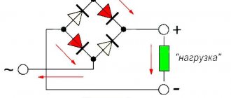
Without a doubt, the leader here is the diode bridge circuit, used in all kinds of rectifiers (Figure 4). It may look different, the principle of operation is the same, I think everything is clear from the drawing. By the way, the last option is a symbol for the diode bridge as a whole. Used to simplify the designation of the two previous schemes.
Below are a few less obvious circuits (for DC):
- Diodes can act as “decoupling” elements. The control signals Control1 and Control2 are combined at point A, and there is no mutual influence of their sources on each other. By the way, this is the simplest version of the “or” logic circuit implementation.
- Protection against polarity reversal (slang - “protection from fools”). If there is a possibility of incorrect connection of the supply voltage polarity, this circuit protects the device from failure.
- Automatic transition to power from an external source. Since the diode “opens” when the voltage across it reaches Uopen, then when Uext
© 2012-2021 All rights reserved.
The materials presented on the site are for informational purposes only and cannot be used as guidelines or regulatory documents.