Mechanical engineering parts and mechanisms, as well as tools intended for their processing, have a set of mechanical characteristics. Hardness plays a significant role among the characteristics. The hardness of metals clearly shows:
- wear resistance of metal;
- possibility of processing by cutting, grinding;
- resistance to local pressure;
- ability to cut other materials and others.
In practice, it has been proven that most of the mechanical properties of metals directly depend on their hardness.
Hardness concept
The hardness of a material is its resistance to destruction when a harder material is introduced into the outer layer. In other words, the ability to resist deforming forces (elastic or plastic deformation).
The hardness of metals is determined by introducing a solid body called an indenter into a sample. The role of the indenter is performed by: a metal ball of high hardness; diamond cone or pyramid.
After exposure to the indenter, an imprint remains on the surface of the test sample or part, the size of which determines the hardness. In practice, kinematic, dynamic, and static methods of measuring hardness are used.
The kinematic method is based on the compilation of a diagram based on continuously recorded readings that change as the tool is pressed into the sample. Here the kinematics of the entire process is traced, and not just the final result.
The dynamic method is as follows. The measuring tool acts on the part. The reverse reaction allows you to calculate the expended kinetic energy. This method allows you to test the hardness of not only the surface, but also a certain volume of metal.
Static methods are non-destructive methods that allow you to determine the properties of metals. The methods are based on smooth indentation and subsequent holding for some time. The parameters are regulated by methods and standards.
The applied load can be applied:
- pressing;
- scratching;
- cutting;
- rebound
Machine-building enterprises currently use the Brinell, Rockwell, Vickers methods, as well as the microhardness method, to determine the hardness of materials.
Based on the tests carried out, a table is compiled indicating the materials, the applied loads and the results obtained.
General classification of metal materials
Metals (from Latin metallum - mine, mine) are a group of elements with characteristic metallic properties, such as high thermal and electrical conductivity, positive temperature coefficient of resistance, high ductility and metallic luster.
Depending on their density, metals are divided into light (density 0.53 h 5 g/cm³) and heavy (5 h 22.5 g/cm³). The lightest metal is lithium (density 0.53 g/cm). It is currently impossible to name the heaviest metal, since the densities of osmium and iridium - the two heaviest metals - are almost equal (about 22.6 g / cm - exactly twice the density of lead), and it is extremely difficult to calculate their exact density: for this It is necessary to completely clean the metals, because any impurities reduce their density.
Black. These are metals that contain iron. They may have small amounts of other metals or other elements added to give the required properties (chromium, manganese, vanadium, etc.).
Hardness Units
Each method of measuring the resistance of a metal to plastic deformation has its own methodology, as well as units of measurement.
The hardness of soft metals is measured using the Brinell method. Non-ferrous metals (copper, aluminum, magnesium, lead, tin) and alloys based on them, cast iron (except for white) and annealed steel are subjected to this method.
Brinell hardness is determined by indentation of a hardened, polished ball made of ShKh15 ball bearing steel. The circumference of the ball depends on the material being tested. For hard materials - all types of steel and cast iron - 10 mm, for softer materials - 1 - 2 - 2.5 - 5 mm. Required load applied to the ball:
- iron alloys – 30 kgf/mm²;
- copper and nickel – 10 kgf/mm²;
- aluminum and magnesium – 5 kgf/mm².
The unit of hardness measurement is a numerical value followed by a numerical index HB. For example, 200 NV.
Rockwell hardness is determined by the difference in applied loads to the part. First, a preliminary load is applied, and then a general load, at which the indenter is introduced into the sample and held.
A pyramid (cone) of diamond or a ball of tungsten carbide (hardened steel) is introduced into the test sample. After removing the load, the depth of the indentation is measured.
The unit of measurement for hardness is conventional units. It is generally accepted that one is the amount of axial displacement of the cone, equal to 2 μm. The hardness designation is marked with three letters HR (A, B, C) and a numerical value. The third letter in the marking indicates the scale.
The technique reflects the type of indenter and the load applied to it.
| Scale type | Tool | Applied load, kgf |
| A | Diamond cone with 120° apex angle | 50-60 |
| IN | 1/16" ball | 90-100 |
| WITH | Diamond cone with 120° apex angle | 140-150 |
Basically, measurement scales A and C are used. For example, the hardness of steel is HRC 26...32, HRB 25...29, HRA 70...75.
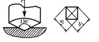
Products of small thickness or parts with a thin, hard surface layer are measured by Vickers hardness. The blade used is a regular tetrahedral pyramid with an apex angle of 136°. The display of hardness values is as follows: 220 HV.
Hardness measurement using the Shore method is carried out by measuring the rebound height of a fallen striker. Indicated by numbers and letters, for example, 90 HSD.
Microhardness is determined when it is necessary to obtain the values of small parts, thin coatings, or individual alloy structures. The measurement is made by measuring the imprint of a tip of a certain shape. The value notation looks like this:
Н□ 0.195 = 2800, where
□ — tip shape;
0.196 — tip load, N;
2800 – numerical value of hardness, N/mm².
Requirements for the controlled product
Fulfillment of primary requirements is a prerequisite for accurate measurements!
- The surface to be tested must be carefully prepared to avoid any changes in hardness caused by heat during grinding or by hardening during processing. Any paint, scale, dents or other surface coatings or imperfections must be completely removed. The surfaces to be tested must be smooth. Failure to provide proper surface treatment will result in measurement deviations. Rough processing of the controlled surface will distort the measurement results. It is recommended that the surface to be tested be subjected to mechanical processing - grinding or polishing. The grain size of grinding materials recommended to achieve a given surface finish is determined when developing a technological map for a specific product.
- Performing a hardness test on parts with a residual magnetic field may affect the results. It is recommended that any residual magnetic field be less than 4 10-4 T (Tesla) or less than 4 Gauss (Gaussian, centimeter-gram-second).
- It is advisable to control the hardness of products made from structural steels after volumetric heat treatment, which ensures uniformity of the structure and physical and mechanical properties, including hardness, throughout the controlled volume.
- When monitoring the hardness of cast products (cast iron, aluminum alloys, silumins, products made of austenitic cast alloys), it is necessary to take into account structural anisotropy, i.e. differences in hardness in different areas. In this regard, for foundry products it is mandatory to install a permanent hardness control point. This will provide the possibility of comparative assessment of the hardness of individual products in one batch and between batches.
- To prevent errors resulting from transducer movement, the base of the support ring should be pressed firmly and perpendicular to the surface of the test piece.
- The sensor and instrument are calibrated to direct the impact vertically downwards (perpendicular to the horizontal surface). For other impact directions, for example, 45 ° from the horizontal plane or others, the measured hardness values should be used with mandatory correction. The Tukan K-18A hardness tester has an automatic correction function.
- The distance between any two points of impact of the indenter must be at least twice the diameter of the indentation. The distance between the point of impact and the edge of the sample must be at least 5 mm. Repeated measurements in the same place are not allowed.
- Test parts with curved surfaces can be tested provided that the radius of curvature of the samples on the convex or concave surfaces of the ring is at least 30 mm.
- To eliminate the influence of inhomogeneity of the product material, it is recommended to use at least 5 measurements over an area of approximately 2.5 cm2 (625 mm2). If the material being tested is considered obviously inhomogeneous (for example, cast iron), the number of measurements on the test area should be increased to 10.
- The thickness and weight of the test sample must be taken into account when making measurements and choosing a testing location. For a type D sensor, the ASTM 956 standard recommends the following minimum dimensions and weight of the product: weight - 5 kg, thickness - 3 mm. According to the standard, if the test products have a mass less than the minimum or parts of any weight have sections less than the minimum thickness, it requires rigid support and adhesion to a massive, non-yielding surface to prevent free vibrations from the impact of the sensor indenter. But, as described above, Iskroline specialists have developed a calibration correction method that makes it possible to significantly weaken these restrictions and reduce the requirements for the mass and minimum dimensions of the test product.
Black metals
The Rockwell hardness of cast iron SCH20 HRC 22, which corresponds to 220 HB. Steel: tool – 640-700 HB, stainless steel – 250 HB.
To convert from one measurement system to another, tables are used. The values in them are not true, because they are derived imperially. Not the full volume is presented in the table.
| HB | H.V. | H.R.C. | HRA | HSD |
| 228 | 240 | 20 | 60.7 | 36 |
| 260 | 275 | 24 | 62.5 | 40 |
| 280 | 295 | 29 | 65 | 44 |
| 320 | 340 | 34.5 | 67.5 | 49 |
| 360 | 380 | 39 | 70 | 54 |
| 415 | 440 | 44.5 | 73 | 61 |
| 450 | 480 | 47 | 74.5 | 64 |
| 480 | 520 | 50 | 76 | 68 |
| 500 | 540 | 52 | 77 | 73 |
| 535 | 580 | 54 | 78 | 78 |
Hardness values, even if produced by the same method, depend on the applied load. The lower the load, the higher the readings.
Hardness measurement methods
All methods for determining the hardness of metals use mechanical action on the test sample - indentation of an indenter. But this does not destroy the sample.
The Brinell hardness method was the first to be standardized in materials science. The principle of testing samples is described above. It is subject to GOST 9012. But you can calculate the value using the formula if you accurately measure the imprint on the sample:
HB=2P/(πD*√(D2-d2), where
P – applied load, kgf; D – ball circumference, mm; d – imprint circumference, mm.
Brinell hardness test principle
The ball is selected relative to the thickness of the sample. The load is pre-calculated from accepted standards for the relevant materials:
iron alloys - 30D²;
copper and its alloys - 10D²;
babbitts, lead bronzes - 2.5D².
Schematically, the Rockwell research method is depicted as follows according to GOST 9013.
Rockwell hardness measuring principle
The final applied load is equal to the sum of the initial load and that required for the test. The device indicator shows the difference in penetration depth between the initial load and the test load h –h0.
The Vickers method is regulated by GOST 2999. It is schematically depicted as follows.
Vickers hardness measuring principle
Mathematical formula for calculation:
HV=0.189*P/d² MPa
HV=1.854*P/d² kgf/mm²
The applied load varies from 9.8 N (1 kgf) to 980 N (100 kgf). The values are determined from the tables relative to the measured print d.
Principle of determining Shore hardness
The method is considered empirical and has a wide range of readings. But the device has a simple design and can be used when measuring large-sized and curved parts.
The Mohs hardness of metals and alloys can be measured by scratching. Mohs at one time proposed making scratches on the surface of an object with a harder mineral. He classified known minerals by hardness into 10 positions. The first is occupied by talc, and the last by diamond.
After measurement using one method, transfer to another system is very conditional. Clear values exist only in the Brinell and Rockwell hardness ratios, since machine-building enterprises widely use them. The dependence can be observed when the diameter of the ball changes.
| d, mm | HB | HRA | H.R.C. | HRB |
| 2,3 | 712 | 85,1 | 66,4 | – |
| 2,5 | 601 | 81,1 | 59,3 | – |
| 3,0 | 415 | 72,6 | 43,8 | – |
| 3,5 | 302 | 66,7 | 32,5 | – |
| 4,0 | 229 | 61,8 | 22 | 98,2 |
| 5,0 | 143 | – | – | 77,4 |
| 5,2 | 131 | – | – | 72,4 |
As can be seen from the table, increasing the diameter of the ball significantly reduces the readings of the device. Therefore, machine-building enterprises prefer to use measuring instruments with the same type of indenter size.
Table of relationships between hardness numbers according to Brinell, Rockwell, Vickers, Shore
Rockwell, Vickers and Shore hardness values indicated correspond to Brinell hardness values determined using a 10 mm diameter ball.
| According to Rockwell | According to Brinell | Vickers (HV) | By Shore | |||
| H.R.C. | HRA | HRB | Imprint diameter | HB | ||
| 65 | 84,5 | – | 2,34 | 688 | 940 | 96 |
| 64 | 83,5 | – | 2,37 | 670 | 912 | 94 |
| 63 | 83 | – | 2,39 | 659 | 867 | 93 |
| 62 | 82,5 | – | 2,42 | 643 | 846 | 92 |
| 61 | 82 | – | 2,45 | 627 | 818 | 91 |
| 60 | 81,5 | – | 2,47 | 616 | – | – |
| 59 | 81 | – | 2,5 | 601 | 756 | 86 |
| 58 | 80,5 | – | 2,54 | 582 | 704 | 83 |
| 57 | 80 | – | 2,56 | 573 | 693 | – |
| 56 | 79 | – | 2,6 | 555 | 653 | 79,5 |
| 55 | 79 | – | 2,61 | 551 | 644 | – |
| 54 | 78,5 | – | 2,65 | 534 | 618 | 76,5 |
| 53 | 78 | – | 2,68 | 522 | 594 | – |
| 52 | 77,5 | – | 2,71 | 510 | 578 | – |
| 51 | 76 | – | 2,75 | 495 | 56 | 71 |
| 50 | 76 | – | 2,76 | 492 | 549 | – |
| 49 | 76 | – | 2,81 | 474 | 528 | – |
| 48 | 75 | – | 2,85 | 461 | 509 | 65,5 |
| 47 | 74 | – | 2,9 | 444 | 484 | 63,5 |
| 46 | 73,5 | – | 2,93 | 435 | 469 | – |
| 45 | 73 | – | 2,95 | 429 | 461 | 61,5 |
| 44 | 73 | – | 3 | 415 | 442 | 59,5 |
| 42 | 72 | – | 3,06 | 398 | 419 | – |
| 40 | 71 | – | 3,14 | 378 | 395 | 54 |
| 38 | 69 | – | 3,24 | 354 | 366 | 50 |
| 36 | 68 | – | 3,34 | 333 | 342 | – |
| 34 | 67 | – | 3,44 | 313 | 319 | 44 |
| 32 | 67 | – | 3,52 | 298 | 302 | – |
| 30 | 66 | – | 3,6 | 285 | 288 | 40,5 |
| 28 | 65 | – | 3,7 | 269 | 271 | 38,5 |
| 26 | 64 | – | 3,8 | 255 | 256 | 36,5 |
| 24 | 63 | 100 | 3,9 | 241 | 242 | 34,5 |
| 22 | 62 | 98 | 4 | 229 | 229 | 32,5 |
| 20 | 61 | 97 | 4,1 | 217 | 217 | 31 |
| 18 | 60 | 95 | 4,2 | 207 | 206 | 29,5 |
| – | 59 | 93 | 4,26 | 200 | 199 | – |
| – | 58 | – | 4,34 | 193 | 192 | 27,5 |
| – | 57 | 91 | 4,4 | 187 | 186 | 27 |
| – | 56 | 89 | 4,48 | 180 | 179 | 25 |
Threaded holes
Table of drills for holes for cutting cylindrical pipe threads.
Wrench nut sizes
Basic spanner dimensions for hex bolt heads and hex nuts.
Read also: How to determine cable cross-section by eye
G and M codes
Examples, description and interpretation of L and M codes for creating control programs on CNC milling and lathes.
Thread types
Types and characteristics of metric, pipe, thrust, trapezoidal and round threads.
Drawing scales
Standard scales for images of parts on mechanical engineering and construction drawings.
Cutting modes
Online calculator for calculating cutting conditions during turning.
Threaded holes
Table of drills and holes for cutting metric threads with large (main) pitch.
CNC machines
Classification of CNC machines, CNC machines for metal for turning, milling, drilling, boring, threading, reaming, countersinking.
Cutting modes
Online calculator for calculating cutting conditions when milling.
Drawing formats
Table of side sizes of main and additional formats of drawing sheets.
CAD/CAM/CAE systems
CAD computer-aided design systems, 3D programs for design, modeling and creation of 3D models.