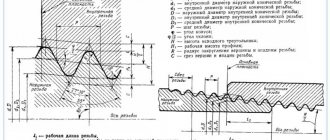
What is metric thread
Thin metric threads are more susceptible to galling. They require long gears and are less suitable for high speed assembly. Thin threads can penetrate hard materials more easily, require less torque, and have little tendency to loosen. They are also stronger than coarse thread and allow for finer adjustments due to their smaller pitch. Coarse threads have a larger pitch and are easier to use than fine thread fasteners, and are designed for most applications.
Basic GOSTs
All hardware and fasteners with screw threads according to the metric measurement system are manufactured in accordance with state and international standards and regulations. Therefore, they may differ in class, size and some other parameters, but they must comply with the permitted requirements and permissible values. Otherwise, the products cannot be certified and used in the production sector. In addition, official sales of such products are prohibited.
Fasteners with metric screw threads are regulated by several regulatory documents:
- GOST 8724, which specifies the permissible values of diameter and pitch;
- GOST 24705 2004 contains information on the main dimensions of metric threads;
- GOST 9150 includes the necessary information about the metric thread profile;
- GOST 16093 prescribes tolerances and designations for products.
Metric threads are also regulated by the international standard ISO 261-98. Russian GOST 8724-2002 completely repeats its text in Russian. True, it contains additions that are characteristic of the needs of the Russian economy.
TECHNOLOGICAL ELEMENTS OF THREAD
The technological elements of threads include runs, undercuts, grooves and chamfers. The shape and dimensions of these elements, depending on the thread profile, are established by the relevant GOST standards.
The thread run-out is the section of the thread in which the cutting tool, emerging from the metal (or other material) to the surface, cuts a thread with a gradual decrease in the profile height. The carving in the drawing, as a rule, is shown without a runoff, but if it needs to be shown, then the runway is shown with thin, solid straight lines, as shown in Fig. 406. The size of the thread length in the drawing is indicated before the run-out, but if necessary, indicate the length of the thread with the run-out (Fig. 406, b)
or indicate the length of the thread before the run-out and the amount of run-out (
x
) (Fig. 406,
a).
In the drilled blind hole, a conical recess is formed from the drill, which is always drawn in the drawing with an angle at the apex of the cone equal to 120° (Fig. 406, b).
The dimensions of this recess are not indicated in the drawing.
The hole drilling depth ( l
) is set without taking into account the cone.
The determining size for the rungs is the thread pitch P.
The undercut of the thread is the area that includes the rung and the remaining uncut part of the rod or hole (Fig. 407). An undercut occurs when cutting a thread point-blank, when there is a protruding surface on the rod and the bottom in the hole prevents further passage of the cutting tool (Fig. 407, a and b).
The dimensions of undercuts are established by GOST 10549-80.
The determining size is the thread pitch P.
It is allowed to depict an undercut with thin solid lines, as shown in Fig.
407, v.
Grooves are performed when cutting threads on machines using a cutter in order to avoid thread runaway and obtain its full profile, as well as to ensure free exit of the cutting tool. To do this, the diameter of the external groove is made smaller than the internal diameter of the thread, and the diameter of the internal groove is larger than the external diameter of the thread (Fig. 408).
In the drawings, grooves are depicted in a simplified manner and, if necessary, explained with a remote element on which the shape of the groove is shown and its dimensions are indicated (Fig. 408). Depending on the scale at which the drawing is made, it is possible to depict the shape of the groove and plot its dimensions on the image of the part itself, as shown in Fig. 409. The dimensions of the groove and its shape are established by GOST 10549-80, depending on the type of thread and its pitch.
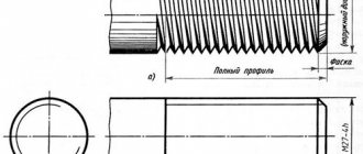
Chamfers are made at the end of the rod and at the beginning of the hole. They simplify the thread cutting process and contribute to a more convenient and quick connection of two parts, like guide elements. The chamfer is a small truncated cone, the height of which is indicated by the letter z
, and the angle of inclination of the generatrices is 45° (Fig. 409 and 410). The dimensions of chamfers for metric threads are established by GOST 10549-80.
GOST 10549-80 Thread exit. Runs, undercuts, grooves and chamfers
Runs, undercuts, grooves and chamfers
Screw thread runout. Washout threads, total thread runouts, undercuts and chamfers
Date of introduction 1982-01-01
1. DEVELOPED AND INTRODUCED by the USSR State Committee for Standards
2. APPROVED AND ENTERED INTO EFFECT by Resolution of the USSR State Committee for Standards dated 07/09/80 N 3501
3. INSTEAD GOST 10549-63
4. REFERENCE REGULATIVE AND TECHNICAL DOCUMENTS
Designation of the referenced technical document
5. The validity period has been lifted according to Protocol No. 3-93 of the Interstate Council for Standardization, Metrology and Certification (IUS 5-6-93)
6. EDITION with Amendment No. 1, approved in December 1986 (IUS 3-87)
1. This standard establishes the dimensions of the thread run-out when the tool exits or if there is a chamfer on the tool, the dimensions of the undercut when making a thread at the stop, the shape and dimensions of the grooves for the exit of the thread-forming tool, the dimensions of the chamfers - for metric, cylindrical pipe, tapered pipe, tapered threads inch with a profile angle of 60° and trapezoidal.
(Changed edition, Amendment No. 1).
2. The dimensions of runs and undercuts for external metric threads must correspond to those indicated in Figures 1 and 4 (when making threads by cutting), in Figures 2, 3 and 5 (when making threads by rolling) and in Table 1.
It is allowed to use an angle of 60°
Dimensions in millimeters
at the angle of the intake part of the tool
when mating with internal thread with groove type 2
for all other cases
1. Type 2 grooves reduce stress concentration under the head, but reduce the bearing surface area.
2. The dimensions of the grooves for a given thread pitch can be set according to the nearest tabulated thread pitch.
3. For parts made of high-strength materials with 1400 MPa and in cases where the groove, in addition to technological, also has structural functions, it is allowed to use grooves not established by this standard.
The shape and dimensions of the grooves for external metric threads must correspond to those indicated in Figure 6 and Table 1. The dimensions of the chamfers of external metric threads are indicated in Figure 1 and Table 1.
3. The dimensions of runs and undercuts for internal metric threads must correspond to those indicated in Figure 7 and Table 2.
It is allowed to use an angle of 60°
The shape and dimensions of the grooves for internal metric threads must correspond to those indicated in Figure 8 and Table 2. The dimensions of the chamfers of the internal metric thread are indicated in Figure 7 and Table 2.
when mating with external thread with groove type 2
for all other cases
_____________ * The width of the grooves is given for diameters of 6 mm or more.
1. Type 2 grooves reduce stress concentration under the head.
2. The dimensions of the grooves for a given thread pitch can be set according to the nearest tabulated thread pitch.
Articles on technical topics from periodicals of the “Regional Center for Innovative Technologies” Basics of threads and threaded connections
Basics of threads and threaded connections
Content
1. Thread 2 1.1. Basics of thread formation 1.2. Thread classification 1.2.1. Metric thread 1.2.2. Inch thread 1.2.3. Pipe cylindrical thread 1.2.4. Pipe conical thread 1.2.5. Trapezoidal thread 1.2.6. Thrust thread 1.2.7. Round thread 1.2.8. Rectangular thread 1.3. Conventional image of a thread. GOST 2.311–68 1.3.1. Conventional image of the thread on the rod 1.3.2. Conventional image of the thread in the hole 1.3.3. Conventional image of the thread assembly 1.4. Conventional image of threads 1.5. Technological thread elements 1.5.1. Threaded chamfers. GOST 10549–80 1.5.2. Threaded grooves. GOST 10549–80 2. Threaded connections 2.1. Threaded connections with non-standard parts 2.2. Simplified bolt connection. GOST 2.315–68 2.3. The pin connection is simplified. GOST 2.315–68 2.4. The screw connection is simplified. GOST 2.315–68 Literature
Thread
Thread is a surface formed by the screw movement of a flat contour along a cylindrical or conical surface.
Scheme 1.1
1.1. Thread Formation Basics
The formation of threads is based on the principle of obtaining a helical line. A helical line is a spatial curve that can be formed by a point moving along the generatrix of any surface of rotation, while the generatrix itself performs a rotational movement around an axis. If we take a cylinder as a surface, then the trajectory of a point obtained on its surface is called a cylindrical helix. If the movement of a point along a generatrix and the rotation of the generatrix around an axis are uniform, then a helical cylindrical line is a line of constant pitch. On the development of the side surface of the cylinder (Fig. 1.1.1), such a helical line is converted into a straight line.
Fig.1.1.1
If a groove is cut along a helical line on the surface of a cylinder or cone, the cutting edge of the cutter forms a helical surface, the nature of which depends on the shape of the cutting edge. The formation of a helical protrusion can be represented as the movement of a triangle, trapezoid, square along the surface of a cylinder or cone so that all points of the figure move along a helical line (Fig. 1.1.2). If the rise of the screw protrusion on the visible (front) side goes from left to right, the thread is called right-handed, if the rise of the screw protrusion goes from right to left - left-handed. If two, three or more flat profiles move simultaneously along the surface, evenly spaced around the circumference relative to each other, then two- and three-lead screws are formed.
Fig.1.1.2
As an example of the formation of single-, double- and triple-start threads, we can consider the process of winding a wire of triangular cross-section onto a cylindrical surface (the turns fit tightly to each other). For a single-start thread (Fig. 1.1.3, a) the screw stroke value Рh
to
step
R. For two- (Fig. 1.1.3, b) and three-lead (Fig. 1.1.3, c) screws, when simultaneous winding of two and three wires of the indicated section is carried out, the stroke value is respectively equal to 2P
- for a two-lead screw and
ZR
- for three-way The above provisions, with some changes and clarifications, can also be applied to a conical surface.
Fig.1.1.3
1.2. Thread classification
Table 1.2.1
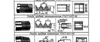
| Thread profile (some parameters) | Conventional image of the thread | Standard | Notation examples | Examples of threaded connection designations | ||
| 1 | 2 | 3 | 4 | 5 | 6 | 7 |
| 1 | Metric | Profile according to GOST 9150-81 (ST SEV180-75) Main dimensions according to GOST 24705-81 (ST SEV182-75) Diameter and pitches according to GOST 8724-81 (ST SEV 181-75) | ||||
| 2 | Metric conical | GOST 25229-82 (ST SEV304-76) | MK 20x1.5 MK 20x1.5LH | |||
| 3 | Pipe cylindrical | GOST 6357-81 (ST SEV 1157-78) | ||||
| 4 | Pipe conical | GOST 6211-81 (ST SEV 1159-78) | ||||
| 5 | Conical inch | GOST 6111-5 | K 1/2″ GOST 6111-52 | |||
| 6 | Trapezoidal | GOST 24737-81 ST SEV838-78 Single-start thread Profile according to GOST 9481-81 | ||||
| 7 | Persistent | GOST 10177-82 ST SEV 1781-79 | ||||
| 8 | Round | GOST 13536-68 | Kr12x2.54 GOST According to ST SEV307-76 Rd 16 Rd 40LH | Kr12x2.54 GOST Rd 16 Rd 40LH | ||
| 9 | Rectangular |
1.2.1. Metric thread
Metric thread (see Table 1.2.1) is the main type of fastening thread. The thread profile is established by GOST 9150–81 and is an equilateral triangle with a profile angle α = 60°. The thread profile on the rod differs from the thread profile in the hole in the amount of blunting of its peaks and valleys. The main parameters of a metric thread are: nominal diameter - d(D) and thread pitch - P, established by GOST 8724–81. According to GOST 8724–81, each nominal thread size with a large pitch corresponds to several small steps. Fine-pitch threads are used in thin-walled connections to increase their tightness, to carry out adjustments in precision mechanics and optics devices, to increase the resistance of parts to self-unscrewing. If the diameters and pitches of threads cannot satisfy the functional and design requirements, ST SEV 183–75 “Metric threads for instrument making” was introduced. If several step values correspond to one diameter, then the larger steps are used first. The diameters and pitches of threads indicated in brackets are not used if possible. In the case of using conical metric (see Table 1.2.1) threads with a taper of 1:16, the thread profile, diameters, pitches and main dimensions are established by GOST 25229–82. When connecting an external conical thread with an internal cylindrical thread according to GOST 9150–81, it must be ensured that the external conical thread is screwed in to a depth of at least 0.8.
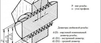
1.2.2. Inch thread
Currently, there is no standard regulating the main dimensions of inch threads. The previously existing OST NKTP 1260 has been canceled, and the use of inch threads in new developments is not allowed. Inch threads are used when repairing equipment, since parts with inch threads are in use. The main parameters of an inch thread are: the outer diameter, expressed in inches, and the number of steps per inch of the length of the cut part of the part.
1.2.3. Pipe cylindrical thread
In accordance with GOST 6367–81, a cylindrical pipe thread has an inch thread profile, i.e. an isosceles triangle with an apex angle of 55° (see Table 1.2.1). The thread is standardized for diameters from 1/16″ to 6″ with the number of steps z from 28 to 11. The nominal thread size is conventionally related to the internal diameter of the pipe (to the nominal diameter). Thus, a thread with a nominal diameter of 1 mm has a nominal diameter of 25 mm and an outer diameter of 33.249 mm.
Pipe threads are used to connect pipes, as well as thin-walled cylindrical parts. This type of profile (55°) is recommended for increased requirements for the tightness (tightness) of pipe connections. Pipe threads are used when connecting the cylindrical threads of the coupling with the conical threads of pipes, since in this case there is no need for various seals.
1.2.4. Pipe tapered thread
The parameters and dimensions of conical pipe threads are determined by GOST 6211–81, according to which the thread profile corresponds to the profile of an inch thread (see Table 1.2.1). The thread is standardized for diameters from 1/16″ to 6″ (in the main plane, the thread dimensions correspond to the dimensions of a cylindrical pipe thread). Threads are cut on a cone with a taper angle φ/2 = 1°47'24" (as for metric tapered threads), which corresponds to a taper of 1:16. The thread is used for threaded connections of fuel, oil, water and air pipelines of machines and machine tools.
1.2.5. Trapezoidal thread
Trapezoidal thread has the shape of an isosceles trapezoid with an angle between the sides equal to 30° (see Table 1.2.1). The main dimensions of diameters and pitches of trapezoidal single-start threads for diameters from 10 to 640 mm are established by GOST 9481–81. Trapezoidal threads are used to convert rotational motion into translational motion under significant loads and can be single- and multi-start (GOST 24738–81 and 24739–81), as well as right and left.
1.2.6. Thrust thread
The thrust thread, standardized by GOST 24737–81, has a profile of an unequal trapezoid, one of the sides of which is inclined to the vertical at an angle of 3°, i.e. the working side of the profile, and the other at an angle of 30° (see Table 1.2.1) . The profile shape and pitch diameters for persistent single-start threads are established by GOST 10177–82. The thread is standardized for diameters from 10 to 600 mm with pitches from 2 to 24 mm and is used for large unilateral forces acting in the axial direction.
1.2.7. Round thread
Round threads are standardized. The profile of a round thread is formed by arcs connected to each other by sections of a straight line. The angle between the sides of the profile is α = 30° (see table 1.2.1). Threads are used to a limited extent: for water supply fittings, in some cases for crane hooks, and also under conditions of exposure to aggressive environments.
1.2.8. Rectangular thread
Rectangular threads (see Table 1.2.1) are not standardized, since, along with the advantages of a higher efficiency than trapezoidal threads, they are less durable and more difficult to manufacture. Used in the manufacture of screws, jacks and lead screws.
1.3. Conventional image of a thread. GOST 2.311–68
Constructing a helical surface in a drawing is a long and complex process, therefore, in product drawings, threads are depicted conditionally, in accordance with GOST 2.311–68. The helix line is replaced by two lines - a solid main line and a solid thin line.
Threads are divided according to their location on the surface of the part into external and internal.
1.3.1. Conventional image of a thread on a rod
Fig.1.3.1.1
The external thread on the rod (Fig. 1.3.1.1) is depicted by solid main lines along the outer diameter and solid thin lines along the internal diameter, and in images obtained by projection onto a plane perpendicular to the axis of the rod, a thin line is drawn at 3/4 of the circle, and this the line can be open anywhere (it is not allowed to start a solid thin line and end it at the center line). The distance between the thin line and the solid main line should not be less than 0.8 mm and greater than the thread pitch, and the chamfer is not shown in this view. The thread boundary is applied at the end of the full thread profile (before the start of the run) with a solid main line, if it is visible. If necessary, the thread run-out is depicted as a solid thin line.
Fig.1.3.1.2
For technological reasons, a part of the part (rod) may be under-threaded. In total, the undercut of the thread and the run-out represent an undercut of the thread (GOST 10548–80). The thread length is indicated, as a rule, without runoff.
1.3.2. Conventional image of a thread in a hole
Fig.1.3.2.1
Internal thread - depicted as a solid main line along the internal diameter and a solid thin line along the outer diameter. If, when depicting a blind hole, the end of the thread is located close to its bottom, then it is allowed to depict the thread to the end of the hole. Threads with a non-standard profile should be depicted.
1.3.3. Conventional image of the thread assembly e
Fig.1.3.3.1
Sections of a threaded connection in the image on a plane parallel to its axis in the hole show only that part of the thread that is not covered by the thread of the rod.
Hatching in sections and sections is carried out to a solid main line, i.e. to the outer diameter of the male thread and the internal diameter of the female thread.
1.4. Conventional image of threads
Table 1.4.1
| Thread type | Symbol for thread type | Dimensions indicated in the drawing | Thread designation in the drawing | |||
| in images in a plane parallel to the thread axis | on images in a plane perpendicular to the thread axis | |||||
| on the rod | in the hole | on the rod | in the hole | |||
| Metric with large pitch GOST 9150-81 | M | Outer diameter (mm) | ||||
| Metric with large pitch GOST 9150-81 | M | Outer diameter and thread pitch (mm) | ||||
| Trapezoidal single-thread GOST 9484-81 (ST SEV 146-78) | Tr | Outer diameter and thread pitch (mm) | ||||
| Pipe cylindrical GOST 6357-81 (ST SEV 1157-78) | G | Designation in inches | ||||
| Conical inch GOST 6111-52 | R | Designation in inches | ||||
| Pipe conical GOST 6211–81 (ST SEV 1159–78): external and internal | R Rc | Designation in inches | ||||
To designate threads, standards for individual types of threads are used. For all threads, except conical and cylindrical pipe threads, the designations refer to the outer diameter and are placed above the dimension line, on its extension or on the shelf of the leader line. The designations of conical threads and cylindrical pipe threads are applied only on the shelf of the leader line. Threads in the drawing are conventionally designated in accordance with standards for images, diameters, pitches, etc. Metric threads are designated in accordance with GOST 9150–81. Metric thread
is divided into threads with a large pitch, designated by the letter M, indicating the nominal diameter of the cylindrical surface on which the thread is made, for example M12, and threads with a fine pitch, designated by indicating the nominal diameter, thread pitch and tolerance range, for example M24x2–6g or M12x1–6H .
When designating a left-hand thread, put LH after the symbol. Multi-start threads are designated, for example, three-start, M24xZ(P1)LH, where M is the type of thread, 24 is the nominal diameter, 3 is the thread stroke, P1 is the thread pitch. The given designations for left-handed and multi-start threads can be applied to all metric threads. Metric tapered thread
is designated in accordance with GOST 25229–82. The thread designation includes the letters MK. Connections of internal cylindrical threads with external conical threads are used. The dimensions of the profile elements of conical and cylindrical threads are taken according to GOST 9150–81. A connection of this type must ensure screwing in a conical thread to a depth of at least 0.8l (where l is the length of the thread without running). The designation of an internal cylindrical thread consists of the nominal diameter, pitch and standard number (for example: M20x1.5 GOST 25229–82).
Fig.1.4.1
The connection of an internal cylindrical thread with an external conical thread (Fig. 1.4.1) is designated by the fraction M/MK, nominal diameter, pitch and standard number: M/MK 20x1.5LH GOST 25229–82. If there are no special requirements for the tightness of connections of this kind or when seals are used to achieve the tightness of such connections, the standard number in the designation of connections is omitted, for example: M/MK 20x1.5 LH. The tolerance field of the average diameter of the internal cylindrical thread must correspond to 6N according to GOST 16093–81, and the maximum deviation of the internal diameter and cut of the cavities of the internal cylindrical thread is accepted within the following limits: upper limit deviation (+0.12) -g- (+0.15), and the lower limit deviation is 0. Pipe cylindrical thread
.
The thread symbol consists of the letter G, the designation of the thread size, the accuracy class of the average diameter (A or B). For left-hand threads, the designation LH is used. For example, G1 1/2LH–B–40 make-up length, indicated if necessary. The connection of an internal cylindrical pipe thread of accuracy class A with an external pipe conical thread according to GOST 6211–81 is designated as follows: for example, G/Rp–11/2–A. When designating fits, the numerator indicates the accuracy class of the internal thread, and the denominator indicates the external thread. For example: G 11/2–A/B. Pipe tapered thread
. The thread designation includes the letters: R - for tapered external thread, Rc - for tapered internal thread, Rp - for cylindrical internal thread and a designation of the thread size. For left-hand threads, the letters LH are added. The nominal size of the thread, as well as its diameters measured in the main plane, correspond to the parameters of a cylindrical pipe thread having the same nominal size. Therefore, parts with conical pipe threads are often used in connections with parts with cylindrical pipe threads, which ensures a fairly high tightness of the connections. Threaded connections are designated as a fraction, the numerator of which indicates the letter designation of the internal thread, and the denominator - the external thread. Example notation:
— internal pipe cylindrical thread of accuracy class A according to GOST 6357–81. Trapezoidal thread
.
The symbol for a trapezoidal thread consists of the letters Tr, nominal diameter, stroke Pn and pitch P. For example: Tr20x4LH–8H, where LH is the designation of the left-hand thread, 8H is the main thread deviation. If necessary, after the main thread deviation, the make-up length L (in mm) is indicated. For example: Tg40x6–8g–85; 85 – make-up length. The thread is persistent
.
The thread designation consists of the letter S, nominal diameter, pitch and main deviation S80x10–8Н. For left-hand threads, the letters LH are indicated after the thread symbol. For multi-start threads, additionally enter the stroke value together with the letter P and the pitch value. Thus, a double-start thread with a pitch of 10 mm is designated S80x2(P10). Rectangular threads
are not standardized.
When depicting a rectangular thread, it is recommended to draw a local section on which the required dimensions are marked. Special threads
. If a thread has a standard profile, but differs from the corresponding standard thread in diameter or pitch, then the thread is called special. In this case, the inscription Sp is added to the thread designation, and the dimensions of the outer diameter and thread pitch are indicated in the thread designation, for example: Sp.M19x1D A thread with a non-standard profile is depicted as presented in paragraph 9 of Table 1, with the dimensions required for making threads.
1.5. Technological thread elements
Fig.1.5.1
Metric, single-stroke, trapezoidal, cylindrical pipe, conical pipe, inch conical threads with a profile angle of 60° have technological elements associated with the thread exit, which include: run-out, undercut, groove and chamfer.
1.5.1. Threaded chamfers. GOST 10549–80
Chamfers on rods and in threaded holes (except for metric threads) have the shape of a truncated cone with an apex angle of 90° and a height of Z. Chamfers on metric external threads have a cone apex angle of 90° and a given diameter of the smaller base of the cone. Chamfers on metric internal threads have a cone apex angle of 120° and a given diameter of the larger base of the truncated cone. Chamfers are shown only on a projection parallel to the thread axis, or in a section by a plane passing through the thread axis. On a projection onto a plane perpendicular to the thread axis, the chamfer is not shown. Shape and dimensions of chamfers for external metric threads
, fasteners are established by GOST 12414–66 (ST SEV 215–82).
The determining size is the outer diameter of the thread d. The shape and dimensions of chamfers for internal metric threads
are established by GOST 10549–80.
The determining size is the outer diameter of the thread D. The shape and dimensions of the chamfers for trapezoidal threads
are established by GOST 10549–80.
The determining size is the thread pitch R. The shape and dimensions of the chamfers for pipe conical threads
and
conical inch threads
are established by GOST 10549–80.
The determining parameter is the number of thread pitches over a length of 25.4 mm. The shape and dimensions of chamfers for cylindrical pipe threads
are established by GOST 10549–80. The determining parameter is the number of thread pitches over a length of 25.4 mm.
1.5.2. Threaded grooves. GOST 10549–80
Fig.1.5.2.1
A groove (Fig. 1.5.2.1) is made at the end of the thread to allow the tool to exit and obtain a full profile thread along the entire length of the rod or hole. In the drawings of the part, the groove is depicted in a simplified manner and the drawing is supplemented with an extension element on an enlarged scale. The shape and dimensions of external thread grooves (when making threads by cutting) are established by GOST 10549–80 (ST SEV 214–75). The determining size is the thread pitch R. The shape and dimensions of the grooves for internal metric threads are established by GOST 10549–80. The determining size is the thread pitch R. The shape and dimensions of grooves for trapezoidal threads are established by GOST 10549–80. The determining size is the thread pitch R. The shape and dimensions of the grooves for pipe conical threads and conical inch threads are established by GOST 10549–80. The determining parameter is the number of thread pitches over a length of 25.4 mm. The shape and dimensions of grooves for cylindrical pipe threads are established by GOST 10549–80. The determining parameter is the number of thread pitches over a length of 25.4 mm.
Threaded connections
Fig.2.1
Parts of machines and devices are connected with fasteners (Fig. 2.1). In addition, threaded connections of parts are used, one of which has an external thread, and the other has an internal thread. These connections, called detachable connections, can be disassembled without damaging the parts. Drawings of detachable connections are made using the simplifications and conventions recommended by the standards.
2.1. Threaded connection with non-standard parts
In addition to threaded connections made using standard fasteners, threaded connections are widely used in which the thread is made directly on the parts included in the connection. Figure 2.1.1 shows the connection of pipe 1 with fitting 2, made using a union nut 3 and a sleeve 4, pressing the conical flared part of the pipe to the fitting.
Fig.2.1.1
2.2. Simplified bolt connection. GOST 2.315–68
Fig.2.2.1
When depicting bolted connections, the dimensions of the bolt, nut and washer are taken according to the relevant GOSTs. In training assembly drawings, in order to save time, it is recommended to draw a bolt, nut and washer not according to all dimensions taken from GOST, but only according to its diameter and the length of the rod. The remaining dimensions are usually determined by the relative ratios of the bolt and nut elements depending on the thread diameter. GOST 2.315-68 provides for simplified and conventional images of fasteners on assembly drawings. In simplified images (Fig. 2.2.1), the thread is shown along the entire length of the rod of the fastening threaded part. Chamfers, roundings, and gaps between the part rod and the hole are not shown. In views obtained by projection onto a plane perpendicular to the thread axis, the thread on the rod is depicted as a single circle corresponding to the outer diameter of the thread. These same views do not show the washers used in the connection.
2.3. The pin connection is simplified. GOST 2.315–68
Fig.2.3.1
When drawing a stud connection on assembly drawings, it is recommended, as with a bolt connection, to use conditional relationships between the thread diameter d and the dimensions of the nut and washer elements. The length l1 of the screwed-in (seating) end of the stud is selected depending on the material of the part.
2.4. The screw connection is simplified. GOST 2.315–68
In a screw connection (Fig. 2.4.1), as in a stud connection, the threaded part of the screw is screwed into the threaded hole of the part. The screw thread boundary should be slightly higher than the parting line of the parts. The upper parts in the holes do not have threads. There should be gaps between these holes and the screws.
Fig.2.4.1
Literature
1. ESKD. GOST 2.311–68, GOST 2.315–68. 2. Bogolyubov S.K., Voinov A.V. Drawing. M., 1983. 3. Merzon E.D. and others. Mechanical engineering drawing. M. Higher School., 1987. 4. Fedorenko V.A., Shoshin A.I. Handbook of mechanical engineering drawing. L., 1982. 5. Vyatkin G.P. and others. Mechanical engineering drawing. M. Mechanical Engineering., 1985.
Articles: Basics of threads and threaded connections