Why is chamfering necessary?
Processing the ends of sheets or pipe walls is needed for:
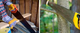
- Good penetration and reliable connection of welding seams
- Reducing welding time
- Preventing injury to employees from sharp corners of the product
- Simplifying the upcoming installation of the metal structure being erected
- To avoid manual sanding of sheet or pipe edges
If chamfering is not performed, then in products whose thickness exceeds 5 mm, the welding seam may come apart over time and the structure will lose strength.
Hatching and filling
Constructing hatching
In order to shade one or more areas, you must:
Rice. 35. Properties panel of the “Hatch” command
Result of executing the Hatch
shown in Fig. 36:
Rice. 36. Hatching an object area
Filling an object
In the KOMPAS-3D system, two types of fill can be created: one-color and gradient. The fill area can consist of one or more closed paths.
In order to fill one or more areas, you must:
Rice. 37. Properties panel of the Fill command
Result of executing the Fill
shown in Fig. 38.
Rice. 38. Gradient fill of an object
Draw three concentric circles of arbitrary diameter and hatch the inner area (Fig. 39):
Rice. 39. Hatching example
Types of chamfers
There are three ways to cut an edge from rolled metal:
- Y-shaped way;
- X-shaped;
- J-shaped (another name is “glass” chamfer);
- Also, in the technical literature you can find another letter designation:
V, K and U-shaped chamfer .
Features of different types of chamfers
- The most common methods of edge removal in production are the Y-shaped method and the X-shaped one.
- For a high-precision weld (for example, on products of complex design), a chamfer with a curved surface is used.
- J-shaped chamfer is performed using special automatic chamfers. This method creates a larger weld pool than other methods.
Other types of edge cutting
(butt type of connection with a broken edge) is not used so often in production.
Bypassing the border along the arrow
Traversing a boundary along an arrow is creating a boundary of an area to perform some operation by sequentially traversing intersecting geometric objects.
In order to switch to working in this mode, you must:
The direction of movement can also be specified using the corresponding buttons on the Property Bar
:
–previous direction;
–next direction;
-step forward;
March 26, 2012
You are familiar with the designation of scale (M), projection of a drawing: front, top, side views - you know the designation of diameter (0), radius (R) of a circle, metric thread (for example, M10, M6).
In working drawings, in addition to front, top, and side views, it may be necessary to show the internal shape of the part.
The internal shapes of the disk can be shown in views using dashed lines.
a - in the figure; 6 - on drawing views.
The disk has three holes and four recesses. The front view has a lot of dashed lines, making it difficult to determine the internal shape of the part. To make the drawing more clear about the internal shapes of the part, sections and sections are used.
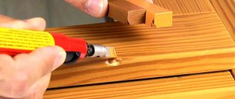
Features of the chamfering process
To cut edges on a metal product, special units are used - bevelers.
, differing in cutting method into three types (air-flame, mechanical and oxygen-gas equipment).
The edge cutting process is as follows:
- Using clamps, the chamfer is attached to the edge of a sheet or the inside of a metal pipe.
- Next, the required sharpening angle is set.
- When the machine is turned on, the cutting head is brought to the workpiece and the chamfer cutting process occurs.
- After finishing the work, the cutter returns to its original position.
- After chamfer cutting, the working surface of the product is considered prepared for further welding work.
When cutting a chamfer, a welding container (bath) is formed, where the hot welding composition is collected. A chamfered edge has a certain dullness of about 3-5 mm. When the container is filled with welding compound, the blunted area melts itself. Thanks to this, the required seam tightness is achieved and additional reliability is created.
General rules for applying dimensions in drawings
The standard (GOST 2.307-68) establishes the rules for applying dimensions in drawings.
Linear dimensions in the drawings are indicated in millimeters without indicating units of measurement (mm). With other units of measurement (centimeters, meters), dimensional numbers are written with the designation of units of measurement (cm, mi). Angular dimensions are indicated in degrees, minutes, seconds with the designation of units of measurement. The total number of dimensions in the drawings should be minimal, but sufficient for the manufacture and control of the product.
There are strictly defined rules for applying dimensions. When applying the size of a straight segment, the dimension line is drawn parallel to this segment, and extension lines are drawn perpendicular to the dimension lines (Fig. 40, b). Extension lines extend beyond the dimensional lines by 1-3 mm. The distance from the dimension line to the outline of the image must be at least 10 mm, and the distance between two adjacent dimension lines must be at least 7 mm (Fig. 40, b).
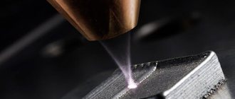
Edge cutting methods
Currently, two methods of edge removal are used in production: thermal and mechanical .
Mechanical chamfer
is considered the highest quality, since this method is performed on special equipment - beveling machines (edge cutters), milling machines, edge splitters and other devices. The advantages of this method are as follows:
- After chamfering, the product retains its structure and does not lose its physical and chemical properties.
- The mechanical method ensures high tightness and reliability of future welds
- Save time.
Thermal method
– air-plasma chamfer and gas-flame chamfer. Air-plasma cutting of edges allows you to obtain a chamfer appearance close to the factory (or mechanical chamfer). However, it requires a perfectly smooth surface of the sheet or pipes at a certain angle. In many industries, this type of chamfering is the main one due to its efficiency and high speed of processing products. It is performed using special plasma cutting equipment.
Gas-plasma chamfering
does not require special conditions for implementation and is characterized by low cost. But the quality of the cut is lower than with the mechanical or air-flame method. Often such chamfer cutting requires additional machining. This method is used for artisanal processing of used pipes. When using the thermal method of chamfer cutting (gas-plasma and air-plasma chamfer cutting), due to overheating, a section appears in the metal product with altered physical and chemical properties (thermal influence zone). This negatively affects the tightness and reliability of future welds and the strength of the structure itself.
Mechanical chamfering preserves the properties of the product and does not affect the quality of future welding work. Mechanical chamfering method
is a kind of guarantor of the quality of processing of metal products before welding. The only “disadvantage” of this method is the high cost of the units and the complexity of the work.
You can find out the cost of mechanical bevel removers by calling ☎ 8-800-555-95-28
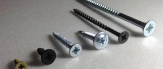
Bevelers of the “Mongoose” series for pipes
Specialized chamfer removers
General rules for applying dimensions in drawings
The standard (GOST 2.307-68) establishes the rules for applying dimensions in drawings.
Linear dimensions in the drawings are indicated in millimeters without indicating units of measurement (mm). With other units of measurement (centimeters, meters), dimensional numbers are written with the designation of units of measurement (cm, mi). Angular dimensions are indicated in degrees, minutes, seconds with the designation of units of measurement. The total number of dimensions in the drawings should be minimal, but sufficient for the manufacture and control of the product.
There are strictly defined rules for applying dimensions. When applying the size of a straight segment, the dimension line is drawn parallel to this segment, and extension lines are drawn perpendicular to the dimension lines (Fig. 40, b). Extension lines extend beyond the dimensional lines by 1-3 mm. The distance from the dimension line to the outline of the image must be at least 10 mm, and the distance between two adjacent dimension lines must be at least 7 mm (Fig. 40, b).
Arrows are placed at the ends of the dimension lines. The shape and dimensions of the arrow are shown in Fig. 40, a. The size of the arrows should be the same throughout the drawing. If there is not enough space, arrows can be replaced with serifs or dots (Fig. 41, b, c). It is allowed to put down dimensions as shown in Fig. 41, g.
Applications
Chamfers are often used in various structural elements to simplify subsequent installation and reduce the risk of injury from sharp edges of parts. So, for example, in mechanical engineering, the chamfer of a fastening hole is often a conical surface, a cutting edge formed by the end surface and the actual cylindrical surface of the hole. The bevel angle is selected based on design purposes, but is often set to 45°. For an interference fit, the recommended bevel angle on the shaft and sleeve is 10°.
In welding, a chamfer or edge groove serves to create a weld puddle between two thick metal sheets, thereby bypassing the maximum thickness limitation of the weld area and welding these sheets to form a high-quality joint. The angle and shape of the chamfer surface is selected from a number of technological and design parameters; chamfers with a curved surface are often used. The size of the chamfer leg is selected according to GOST 10948-64 from the following series of numbers: 0.10; (0.12); 0.16; (0.20); 0.25; (0.30); 0.40; (0.50), 0.60; (0.80); 1.0; (1,2); 1.6; (2.0); 2.5; (3.0); 4.0; (5.0); 6.0; (8.0); 10; (12); 16; (20) and up to 250 mm. Sizes without brackets are preferred.
For sheet metal
Sheet metal is widely used in various fields and areas. Therefore, the sheet beveler is in demand among performers of various levels. Equipment of this type has design features : the presence of support rollers allows the edger to be held on a flat surface, pressed against the end and processed; The ergonomic handle guarantees convenience and ease of moving the unit without much effort.
The MT-24 chamfer is designed for processing the edges of sheet metal materials and is used in the manufacture and installation of metal structures.
CHP-12
CHP-12 is a chamfer tool used for processing single- and double-sided edges of sheet materials made of stainless and carbon steel, aluminum and its alloys.
The manufacturer of this universal installation is the company “CeVisa” (Spain).
It should also be noted that this installation can also be used to work with pipes from 100 mm.
The automatic bevel remover UZ-12 is manufactured by NKO Machines (Czech Republic) . This machine is designed to work along the top and bottom edges, used for processing cast iron, stainless steel, copper, aluminum and brass, and has a high level of productivity. The unit can be installed on a sheet in a vertical or horizontal position.
In the modern market, manufacturers offer consumers a large selection of such tools. Product classification is based on the purpose and type of material used.
In addition, based on the complexity of the functions they perform, pipe chamfers are divided into several groups of devices.
Among the advantages of hand tools, it is worth highlighting the following features:
It is also worth noting some disadvantages of the devices: the unit is not designed to work with large-sized products, which reduces the scope of its operation, manual edge cutters have a lower level of productivity compared to a stationary tool, it is necessary to fix the work part while working with it, and the pipes must be additionally processed before welding them.
Source
What it is
A chamfer is the beveled, rolled edges of a parquet board. They highlight the seam between adjacent boards, emphasize it, giving the surface a voluminous appearance.
Note! The chamfers give the three-layer parquet board the appearance of a more expensive material - solid parquet. This tendency to style cheap materials as expensive ones is in demand, because the building materials market, as we know, is formed by buyers.
There are several types of chamfers based on shape and depth:
The chamfer can be two- or four-sided. In the first case, it is removed only on the side edges of the board, in the second - from all four sides.
Useful: the double-sided chamfer highlights the longitudinal seams. They, in turn, visually lengthen the floor of the room, making it look like a corridor. If wooden parquet is being installed in an already elongated room, the obvious instruction is to prefer a flooring with seams highlighted on all four sides.
This flooring will make the room more elongated in length.
The procedure for independently joining elements
Before replacing pipes with plastic ones, you should select the type of polymer parts used. For independent work, it is recommended to use parts made of polyvinyl chloride.
They have the following advantages:
Method 1. Gluing
Do-it-yourself installation of plastic pipes using gluing is carried out in the following sequence:
Special scissors are used to cut pipes
Photo of beveler for pipes
Advice! When purchasing materials, you should stock up on a slightly larger number of fittings than necessary (especially since their price is low). In this case, if necessary, you can replace one part with another, better one.
Sequence of actions when gluing pipes
Moisture protection methods
The bevels obtained using rolling equipment do not need to be protected from moisture: a melamine film with excellent hydrophobic properties remains on the bevels. But after the cutter, the bevel is not protected by anything. Manufacturers solve the problem in different ways: some are varnished, others are painted with acrylic paints.
During operation, the varnish (paint) layer becomes thinner and begins to let in first steam molecules, and then water. It needs updating. Here, firstly, it is important not to miss the moment when restoration work is needed, and secondly, to have the money and time to maintain the flooring.
Attention: the protective layer on the corners of laminated boards is most often damaged. Therefore, they need special attention if you want to keep the flooring intact for a long time.
Pre-setting the router
Initially, it is important to choose the appropriate type of cutter. There are several types of chamfers. Choose the one that suits your specific task. The suitable cutter is not always included in the set with the router.
But acquiring it will not be difficult. Milling cutters of this kind are freely available in tool stores and cost pennies.
The addition of a vacuum cleaner makes working much easier. When processing wood, there is virtually no waste left.
Sections
In working drawings, in addition to views, they often show an image called a section.
The section shows only what is directly in the cutting plane. The section located in the drawing, but to the side of the image, is called extended. The section on the drawing image itself will be superimposed.
a - taken out; b - imposed.
Incision
is an image of an object mentally dissected by one or more planes.
The section shows what is obtained in the secant plane and located behind it. The figure below shows a part mentally dissected by a plane, and images of the section and section. Unlike a section, a section shows a hole and a groove behind the cutting plane.
On sections and sections, the internal outlines (boundaries) are shown with solid lines, and the surfaces of the part located behind the cutting plane are highlighted by hatching. Sections and sections show holes and indentations.
The figure below contains a drawing of the same disk as in the figure, but instead of a front view, a section is shown. This image allows you to better visualize the disk in the drawing with its invisible contours (holes).
See the picture -
Chamfers
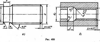
- This is a cut corner or edge of a flat or cylindrical part. A chamfer is removed to improve the appearance or blunt the sharp edges of a part.
a - flat; b - cylindrical.
The drawings of parts indicate the number, width and angles of chamfers. If two chamfers have the same angles and dimensions, then the drawing indicates this: 3*45°/2 chamfers. This means that the part has two chamfers, each 3 mm wide, at an angle of 45°.
If there are several chamfers with different angles or different widths on one part, each chamfer is indicated on the drawing.
Questions
- Why do the drawings show sections and sections?
- What is the difference between a section and a section?
- What lines on sections and sections show internal outlines (boundaries)?
- Why are chamfers made?
- How are chamfers shown in drawings?
“Plumbing”, I.G. Spiridonov, G.P. Bufetov, V.G. Kopelevich
A part is a part of a machine made from a single piece of material (for example, a bolt, nut, gear, lathe lead screw). A node is a connection of two or more parts. The product is assembled according to assembly drawings. A drawing of such a product, which includes several assemblies, is called an assembly drawing; it consists of drawings of each part or assembly and depicts an assembly unit (a drawing of a single...
A technological map is an instruction for completing a task. Technological maps, drawings, sketches, instruction cards - all this is technical documentation that describes the nature and procedure for completing the task. Technological maps indicate the sequence of manufacturing parts, processing sketches, the tool used, the type and material of the workpiece. The manufacturing sequence can be detailed or brief. It all depends on the complexity of the part. IN…
Electrical
RIDGID (video)
This model can work with both pipes and sheet metal.
GTW-2100 is an electric beveling tool for pipes and flat surfaces, suitable for working with steel, stainless steel, non-ferrous metals and other materials.
K1755
K1755 – electric chamfer for metal pipes with an outer diameter of 28-42 mm.
FS-22M Bevel remover FS-22M is an electric device for processing the edges of sheet materials.
FS-22 The FS-22 is designed for processing sheets and pipes made of the following materials: steel, stainless steel and light alloys. Multifunctionality makes this unit popular, so you should familiarize yourself with its technical characteristics.
Wooden floors
When laying floors with wooden boards, you need to take into account many nuances. This includes the quality of the material, the degree of drying, and the conditions under which the surface will be used. While the first two questions can be easily determined in advance, the operating conditions of the floor cannot always be reliably predicted. In this case, a chamfer is used. What this is is explained above. It will not only make the floor look neater and more beautiful, but will also help to avoid visible gaps between the boards, which are sure to appear over time.
When working with solid wood, the question may arise: “How to make a chamfer?” Moreover, a woodworking machine is not entirely suitable for this. First of all, the material is sanded clean (this will be impossible to do later). For chamfering, use an edge cutter on a bearing. This allows you to achieve ideal quality of the processed surface even with slight curvature of the boards.
Laminate
Today, not everyone can afford floors made of solid wood and parquet boards due to the high labor costs and loss of time for repair work. You can increasingly find laminate floors on apartment floors. It is not only easy and quick to lay, but also has excellent performance and aesthetic qualities, in many ways not inferior to natural surfaces.
Currently, laminate flooring with a chamfer on the edge is more often purchased on the market. What is this and how does it affect the final result? First of all, it looks more representative, completely replicating the appearance of natural wood. Secondly, this minor nuance masks changes in the gaps between the boards that appear during the use of the floor.
Many consumers are still skeptical about such flooring. This is argued by the fact that a chamfer in a laminate is unacceptable, as this will allow dust and dirt to accumulate in the recesses and penetrate into the seams. This is not true, because modern material production technologies make it possible to make laminate flooring water- and dirt-proof over its entire surface. A high-quality lock will prevent debris from penetrating into the seams.
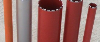
A chamfer is the surface of a product that is formed during the processing of rolled products or pipes by bevelling the end edge of the material. The chamfer is necessary to prepare the edges of sheets, beams and pipes for welding.
The main types of chamfer are:
- "Gas"
. This is the cheapest type of pipe bevel due to its low quality. However, this type is one of the most common. This chamfer is removed using. The “Gas” chamfer can also be made in the field. Its surface usually has characteristic grooves, which are formed from a gas stream (propane or acetylene). - "Plasma"
. Externally, this type of chamfer is practically no different from “mechanics”. It can also be classified as an air plasma cutter, a compressor, and a compressor that forces the cutter to move strictly in a circle when setting a specific bevel angle. - "Mechanics"
. This is a factory chamfer, of the best quality. For chamfering “mechanics” and are used. In the pipe market, this bevel is mainly used due to the high quality of the bevel.
What is the purpose of chamfering? When welding workpieces, metal penetration occurs, which subsequently ensures that the edges are connected to each other. If the metal thickness is more than 3-5 mm, obtaining a complete and high-quality connection becomes difficult. To obtain high-quality penetration, this type of processing is carried out: it allows you to create a so-called weld pool, which is filled with a welding compound during the welding process. It is important to remember that the edge prepared for welding is an edge with a chamfer and bluntness (see the figure and its symbols below).
Types of chamfers (methods of cutting edges).
There are three main methods for preparing edges for welding: Y-shape, X-shape, and J-shape. Sometimes in some sources they are designated by the letters: V, K and U, respectively. Here and below, the above methods will be designated by the letters: Y, XJ Most often, Y-shaped cutting of edges is carried out, but there is also an X-shaped method. In special cases, when there is an increased requirement for the quality of the weld, a J-shaped chamfer is used, that is, a chamfer with a curved surface (not to be confused with a curved edge!).
In addition to the main methods of processing Y, X. J edges, there are a number of edge preparations. They are not so rare, and their description cannot be found everywhere. For example, GOST 5264-80 describes the butt type of connection with a broken edge braid; symbol – C14.
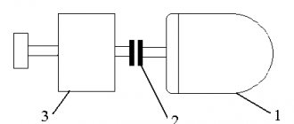
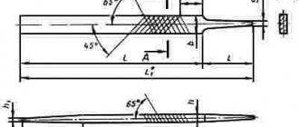
The diagrams above show several examples of processing methods:
1: example of Y-shaped chamfering method;
2, 3, 4: examples of the X-shaped chamfering method;
5: Y-shaped processing of the ends of two pipes with their subsequent connection;
Methods for chamfering.
There are two ways to remove a chamfer: mechanical and thermal (Table 1). Mechanical chamfering is carried out using milling, edge splitting and edge planing machines. For thermal chamfering, gas cutting machines (stationary or portable) are used, which perform plasma or oxy-fuel cutting. However, the more preferable method is mechanical, since it eliminates changes in the physical and chemical properties of the material as a result of overheating. As is known, during heat treatment a so-called thermal influence zone is formed. The thermally affected zone is the carburization of the edge due to overheating of the material, which impairs weldability and increases the fragility and brittleness of the edge. But, despite these disadvantages, the thermal method is quite common due to its simplicity and speed of application, and the relatively low cost of equipment.
Table 1
. Advantages and disadvantages of thermal and mechanical chamfering methods.
Table 1 states that thermal chamfering can be done quickly and cheaply. Of the processing methods described above, mechanical is still preferable, since it allows you to protect the metal from overheating and from subsequent changes in physical and chemical properties. In the West, by the way, this method is called cold-cutting, that is, a type of processing in which there is no thermal effect on the metal, and therefore there are no changes in the chemical and physical properties of the metal.
Video material:
1.
Pipe cutting with a gas cutting machine CG2-11G, simultaneous chamfering of the pipe is carried out by tilting the cutter at the required angle.
2.
Chamfering a 76x6mm pipe using the Mongoose-2MT machine
3.
Chamfering a pipe using a TT series chamfer, as well as cutting a pipe with chamfering using a split pipe cutter P3-SD
The group offers for supply equipment for chamfering pipes and metal using all of the above processing methods (gas, plasma, mechanical).
Usually, when planing wooden blocks or narrow boards, it is often necessary to remove small chamfers from the edges of the workpiece in order to reduce the sharpness of the corners and also make them more beautiful. To do this under normal conditions, you have to hold the workpiece with the plane at angles of about 45 degrees, which is not particularly convenient, especially when you are working with an electric plane, which is many times heavier than a manual one. This problem can be solved using your own special device, which will look like a longitudinal corner, where the block will be placed, which will be processed in the future, and its edge will be located at the top, which is convenient for processing.
This arrangement of the workpiece in a homemade device will also help for planing faceted and round bars, as well as wooden handles, which are inconvenient to process on a flat surface. The author of the homemade product thought about making such a device, since the need for it arose when he was planing blanks for shovel handles, because with such a device the work was completed faster, and it was also much more convenient to work this way.
In order to make this device, you need:
Two wooden planks 2 cm thick, 4 cm wide, and 6 cm, and 2 m long. Wooden plank 2 cm thick, 5 cm wide, and 50 cm long. Wood screws 4x50 mm. Drawing and measuring tools (pencil, tape measure and square). Awl. A jigsaw with a file for curved cutting. Electric drill-screwdriver. Metal drill with a diameter of 4 mm. Spherical cutter for wood. Cross (curly) bit RN2, for driving screws. Sandpaper.
When all the materials and tools are available, then you can begin the most interesting part, this assembly process.
Step one.
The first step is to decide on the dimensions; you can use the dimensions given here, but if your workpiece is large, then simply increase the size of all the components to the required size.
Using a pencil, we mark a plank 6 cm wide, then using a screwdriver and a drill, we drill holes along its entire length, on one side there are 5 or 6 holes for screws, as a rule, the more, the better, and more reliable. Step two.
Having positioned the plank on the opposite side, using a countersink installed in a screwdriver chuck, we increase the dimensions for the screw heads, using a spherical wood cutter.
After we have enlarged the holes for the caps, we insert screws into these holes and screw our plank to the end of another 4 cm wide plank. What should happen at this stage can be seen in the photo, this is the so-called wooden corner, its length is 2 m, made for so that there is a reserve in length used in processing workpieces, thereby increasing the range of application, since you do not have to combine the sizes of either small or large devices, and it is easier and more practical to make one, but longer. Step three.
Using a jigsaw, we cut out a smaller piece from a board, which will be the supporting part, with which the device will be held on a flat surface, this process requires sufficient precision and accuracy; for better accuracy, use a special corner stand on the jigsaw, which will help in creating even cuts.
When working with a jigsaw, be extremely careful and do not forget to wear safety glasses and gloves, protecting yourself from accidental contact with sawdust and wood dust, as well as protecting yourself from the tool slipping out of your hands. Step four.
The previous workpiece, whose role is to hold our corner part, must be drawn, the lines should correspond to an angle of 45 degrees, as on the main part, for a better match, attach the future support and outline it with a pencil.
To secure it, you need to drill holes for the screws, in this case there will be three of them, which is quite enough, we select the drill according to the diameter of the screws so that the thread passes without difficulty. Step five.
Then we tighten the screws with a screwdriver, that is, we screw this workpiece to the end of our corner device, try not to overdo it with the tightening force, so as not to damage the support and form a crack in it.
The remaining part of the strip will also be useful; we make the same blanks from it using a jigsaw; you will need two of these. We supplement the corner with two more supports, which will make it much more stable, and it will also acquire a larger workload, which is also important when processing. We screw them in the same way as the first support. Step six.
The back of the device must be drilled on each side; we use a screwdriver with a drill whose diameter is equal to the thickness of the screw; for strength, we make two holes on each side to prevent rotation.
The location of the holes, as in the previous stages, must be processed with a spherical wood cutter in order to recess the screw heads and thereby eliminate accidental snagging. Step seven.
Armed with a screwdriver and a bat attachment for driving screws, we tighten the screws into the workpieces. Next, we move on to more precise processing, for this we will use sandpaper, as usual, we start with coarser paper, gradually reducing the grain size as we approach the finish of sanding. With this our homemade device is ready, now let’s look at it from all sides for a full assessment. This is what the back looks like. And so the front part. After you make such a device, you will be able to process bars without any difficulties or inconveniences, be it a wooden handle or a workpiece with square edges.
You can chamfer a board in a variety of ways. The most common of them are two: using manual and automatic tools. The negative side of using hand tools (various planes) is considered to be a high degree of injury risk, as well as a catastrophically low pace of work. Of course, automatic and semi-automatic milling cutters are ideal for these purposes.
On the website https://www.zaoportal.ru/product/view/111 you can purchase a professional chamfering machine. The main reason why home craftsmen avoid purchasing such equipment is the apparent difficulty of operation. In fact, setting up and using it for its intended purpose does not cause any difficulties even for a novice user.
Initially, it is important to choose the appropriate type of cutter. There are several types of chamfers. Choose the one that suits your specific task. The suitable cutter is not always included in the set with the router.
But acquiring it will not be difficult. Milling cutters of this kind are freely available in tool stores and cost pennies.
Preparing the milling cutter for work is as follows:
- a hose from a vacuum cleaner is placed in the waste removal socket;
- the cutter position is adjusted;
- the router is fixed in a given position;
- horizontal guides are installed.
The addition of a vacuum cleaner makes working much easier. When processing wood, there is virtually no waste left.
Initially, the cutter height adjustment head must be turned until it clicks. The depth regulator is pulled down 3 mm. Then it lowers onto the head. Thus, we obtain the “zero” position of the cutter.
Now, by rotating the height adjustment head, you can quickly and without much difficulty change the position of the cutter by 5, 10 mm.
The router guides should also be adjusted for correct chamfering. This is achieved quite simply - it is only important to tighten the nuts on the guides until the router slides along the surface being processed, as if on rails.