INFORMATION ON THE APPLICATION OF CENTER HOLE SHAPE
| Center hole shape | Application |
| A | a) In cases where after processing there is no need for center holes. b) In cases where the safety of the center holes during their operation is guaranteed by appropriate heat treatment |
| IN | In cases where the center holes are a base for repeated use, as well as in cases where the center holes are retained in finished products |
| T | For mandrels and plug gauges |
| WITH | For large shafts (same purpose as form A) |
| E | For large shafts (purpose similar to form B) |
| R | In cases where increased processing accuracy is required |
| F | For installation work, transportation, storage and heat treatment of parts in a vertical position |
| N | |
| R | For tool tapers: Morse, metric, etc. |
APPLICATION.
(Changed edition, Amendment No. 1).
Center holes
CENTER HOLES WITH CONE ANGLE 60o (GOST 14034-74) * Size for reference
| D | d | d1 | d2 | d3, to H14 | l, no less | l1 | l2, to H12 | l3, no less | |
| nominal | prev off | ||||||||
| 2,0 | (0,5) | 1,6 | — | — | 0,8 | 0,48 | H11 | — | — |
| 2,5 | (0,63) | 1,32 | — | — | 0,9 | 0,60 | — | — | |
| 3 | (0,8) | 1,70 | 2,50 | — | 1,1 | 0,78 | 1,02 | — | |
| 4 | 1,0 | 2,12 | 3,15 | — | 1,3 | 0,97 | 1,27 | — | |
| 5 | (1,25) | 2,65 | 4,00 | — | 1,6 | 1,21 | H12 | 1,60 | — |
| 6 | 1,6 | 3,35 | 5,00 | — | 2,0 | 1,52 | 1,99 | — | |
| 10 | 2,0 | 4,25 | 6,30 | 7,0 | 2,5 | 1,95 | 2,54 | 0,6 | |
| 14 | 2,5 | 5,30 | 8,00 | 9,0 | 3,1 | 2,42 | 3,20 | 0,8 | |
| 20 | 3,15 | 3,70 | 10,0 | 12,0 | 3,9 | 3,07 | 4,03 | 0,9 | |
| 30 | 4 | 8,50 | 12,50 | 16,0 | 5,0 | 3,90 | 5,06 | 1,2 | |
| 40 | (5) | 10,60 | 16,0 | 20,0 | 6,3 | 4,85 | 6,41 | 1,6 | |
| 60 | 6,3 | 13,20 | 18,0 | 25,0 | 8,0 | 5,98 | 7,36 | 1,8 | |
| 80 | (8) | 17,0 | 22,40 | 32,0 | 10,1 | 7,79 | 9,35 | 2,0 | |
| 100 | 10 | 21,20 | 28,00 | 36,0 | 12,8 | 9,70 | 11,66 | 2,5 | |
| 120 | 12 | 25,40 | 33,0 | — | 14,6 | 11,6 | 13,80 | — | |
| 160 | 16 | 33,90 | 42,50 | — | 19,2 | 15,50 | 18,00 | — | |
| 240 | 20 | 42,40 | 51,60 | — | 25,0 | 19,40 | 22,00 | — | |
| 360 | 25 | 53,00 | 63,30 | — | 32,0 | 24,0 | 27,0 | — | |
Notes:
1. Dimensions enclosed in brackets are not recommended. 2. Dimensions D are recommended.
An example of the designation of a center hole of shape A with a diameter of d = 1 mm:
Hole. center. A1 GOST 14034-74 CENTER HOLES WITH CONE ANGLE 75o (GOST 14034-74) * Size for reference
| D | d | d1 | d2 | l, no less | l1, to H17 | l2, according to H17 |
| 120 | 8 | 23,3 | 30,2 | 10 | 10 | 12,0 |
| 180 | 12 | 36,6 | 45,4 | 15 | 16 | 18,5 |
| 260 | 20 | 60,0 | 70,3 | 22 | 26 | 29,0 |
| 360 | 30 | 91,4 | 105,0 | 32 | 40 | 44,0 |
| 500 | 40 | 120,0 | 137,0 | 43 | 52 | 57,0 |
| 800 | 50 | 150,0 | 170,5 | 52 | 65 | 71,0 |
| 1200 | 63 | 186,0 | 213,7 | 65 | 80 | 88,0 |
Note:
Sizes D are recommended.
An example of the designation of the center hole of a form C with a diameter of d = 8 mm:
Hole. center. C8 GOST 14034-74 CENTER HOLE WITH ARC-SHAPED FORMER (GOST 14034-74)
| D | d | d1 | l, no less | r | |
| least | greatest | ||||
| 2 | (0,5) | 1,30 | 1,3 | 1,30 | 1,60 |
| 2,5 | (0,63) | 1,50 | 1,5 | 1,60 | 2,00 |
| 3 | (0,8) | 1,70 | 1,9 | 2,00 | 2,50 |
| 4 | 1 | 2,12 | 2,3 | 2,50 | 3,15 |
| 5 | (1,25) | 2,65 | 2,8 | 3,15 | 4,00 |
| 6 | 1,6 | 3,35 | 3,5 | 4,00 | 5,00 |
| 10 | 2 | 4,25 | 4,4 | 5,00 | 6,30 |
| 14 | 2,5 | 5,30 | 5,5 | 6,30 | 8,00 |
| 20 | 3,15 | 6,70 | 7,0 | 8,00 | 10,00 |
| 30 | 4 | 8,50 | 8,9 | 10,00 | 12,50 |
| 40 | (5) | 10,60 | 11,2 | 12,50 | 16,00 |
| 60 | 6,3 | 13,20 | 14,0 | 16,00 | 20,00 |
| 80 | (8) | 17,00 | 17,9 | 20,00 | 25,00 |
| 100 | 10 | 21,20 | 22,5 | 25,00 | 31,50 |
Notes:
1. Dimensions enclosed in brackets are not recommended. 2. Dimensions D are recommended.
An example of the designation of a center hole of shape R with a diameter of d = 1 mm:
Hole. center. R1 GOST 14034-74 CENTER HOLES WITH METRIC THREAD (GOST 14034-74) * Dimensions for reference
| D is for shape | d | d1, H14 | d2 | d3 | l, no less | l1, H15 | l2, no more | l3, H15 | α | |
| F | H | |||||||||
| 8 | — | M3 | 3,2 | 5 | — | 2,8 | 1,56 | — | — | 60° |
| 10 | 16 | M4 | 4,3 | 6,5 | 8,2 | 3,5 | 1,90 | 4,0 | 2,4 | |
| 12,5 | 20 | M5 | 5,3 | 8,0 | 11,4 | 4,5 | 2,30 | 5,5 | 3,3 | |
| 16 | 25 | M6 | 6,4 | 10,0 | 13,3 | 5,5 | 3,00 | 6,5 | 4,0 | |
| 20 | 32 | M8 | 8,4 | 12,5 | 16,0 | 7,0 | 3,50 | 8,0 | 4,5 | |
| 25 | 40 | M10 | 11,0 | 15,6 | 19,8 | 9,0 | 4,00 | 10,2 | 5,2 | |
| 32 | 50 | M12 | 13,0 | 18,0 | 22,0 | 10,0 | 4,30 | 11,2 | 5,5 | |
| 40 | 63 | M16 | 17,0 | 22,8 | 28,7 | 11,0 | 5,00 | 12,5 | 6,5 | |
| 63 | 80 | M20 | 21,0 | 28,0 | 33,0 | 12,5 | 6,00 | 14,0 | 7,5 | |
| 100 | M24 | 25,0 | 36,0 | 43,0 | 14,0 | 9,50 | 16,0 | 11,5 | ||
| 160 | M30 | 31,0 | 44,8 | 51,8 | 18,0 | 12,00 | 20,0 | 14,0 | ||
| 250 | M36 | 37,5 | 53,0 | 60,0 | 20,0 | 13,5 | 22,0 | 15,5 | ||
| 400 | M42 | 43,5 | 59,7 | 70,5 | 22,0 | 14,0 | 25,0 | 17,0 | ||
| 630 | M48 | 49,5 | 74,0 | 88,0 | 24,0 | 16,0 | 28,0 | 20,0 | 75° | |
| 900 | M56 | 58,0 | 85,6 | 99,5 | 27,0 | 18,0 | 31,0 | 22,0 | ||
| St. 1200 | M64 | 66,0 | 95,0 | 112,5 | 29,0 | 19,0 | 34,0 | 24,0 | ||
| M72x6 | 74,0 | 104,7 | 122,0 | 31,0 | 20,0 | 36,0 | 25,0 | |||
| M80x6 | 82,0 | 115,7 | 133,0 | 34,0 | 22,0 | 39,0 | 27,0 | |||
| M100x6 | 102,0 | 140,0 | 160,0 | 36,0 | 24,0 | 42,0 | 30,0 | |||
Notes:
1. Dimensions D are recommended. 2. Forms F and H should not be used for cutting and accessory tools with 1:10, 1:7, 7:24, metric and Morse taper shanks.
An example of the designation of a center hole of shape F with a thread diameter d = M3 mm:
Hole. center. F M3 GOST 14034-74 CENTER HOLES WITH METRIC THREAD (GOST 14034-74) recommended * Dimensions for reference
| Designation of cones | d | d1, to H14 | d2 | d3, Н14 | L, not less | l | l1 | l2, no less | ||||
| GOST 25557-2006 | GOST 9953-82 | GOST 7343-72 | GOST 24644-41 | |||||||||
| Metric | Morse | |||||||||||
| — | 1 | B12 | — | — | M6 | 6,4 | 8,0 | 8,5 | 16 | 3,5 | 1,53 | — |
| 2 | B18 | M10 | 10,5 | 12,5 | 13,2 | 24 | 4,5 | 1,90 | — | |||
| 3 | B24 | 30 | M12 | 13,0 | 15,0 | 17,0 | 28 | 6,0 | 2,30 | 0,6 | ||
| 4 | B32 | 40 | M16 | 17,0 | 20,0 | 22,0 | 32 | 8,0 | 3,20 | — | ||
| 5 | B45 | 80 | 45 | M20 | 21,0 | 26,0 | 30,0 | 40 | 10,0 | 5,50 | 1,1 | |
| 90 | ||||||||||||
| 6 | — | — | 50; 55 | M24 | 25,0 | 31,0 | 36,0 | 50 | 11,0 | 6,60 | 1,4 | |
| 80 | — | 100 | 60 | M30 | 31,0 | 38,0 | 45,0 | 65 | 14,0 | 8,0 | 2,0 | |
| (110) | ||||||||||||
| 120 | ||||||||||||
| 140 | ||||||||||||
| 100 | 160 | 65 | M36 | 37,0 | 45,0 | 52,0 | 80 | 15,0 | 9,0 | |||
| 120 | (180) | |||||||||||
| — | 200 | |||||||||||
| — | — | 70 | M36* | 50,0 | 60,0 | 68,0 | 100 | 18,0 | 11,0 | 2,3 | ||
| 160 | M48 | |||||||||||
| 200 | ||||||||||||
Note:
* Thread diameter M36 only for cone No. 70 GOST 24644-81.
APPLICATION OF CENTER HOLE FORMS Form A
- in cases where after processing there is no need for center holes, and in cases where the safety of the center holes during their operation is guaranteed by appropriate heat treatment;
Form B
- in cases where the center holes are a base for repeated use, as well as in cases where the center holes are retained in finished products;
Form T
- for mandrels and plug gauges;
Forms F
and
H
- for installation work, transportation, storage and heat treatment of parts in a vertical position;
Form C
- for large shafts (the purpose is similar to form
A
);
Form E
- for large shafts (the purpose is similar to form
B
);
Form R
- in cases where increased processing accuracy is required;
Form P
- for tool tapers: Morse, metric, etc.
Purpose of center holes of form A, B and T depending on the mass of products (workpieces): (recommended)
| Product weight, kg no more | d, mm | Product weight, kg no more | d, mm | Product weight, kg no more | d, mm |
| 50 | 2 | 200 | 5 | 1.500 | 12 |
| 80 | 2,5 | 360 | 6,3 | 2.500 | 16 |
| 90 | 3,15 | 500 | 8 | 8.000 | 20 |
| 100 | 4 | 800 | 10 | 20.000 | 25 |
Purpose of center holes of shape C and E depending on the mass of products (workpieces): (recommended)
| Product weight, kg no more | d, mm |
| 1.500 | 8 |
| 3.000 | 12 |
| 9.000 | 20 |
| 20.000 | 30 |
| 35.000 | 40 |
| 80.000 | 50 |
| 120.000 | 63 |
DATA FOR SELECTING CENTER HOLES DEPENDING ON THE WEIGHT OF PRODUCTS (WORKPIECES)
| Product weight, kg, no more | d, mm | Center hole shape | Product weight, kg, no more | d, mm | Center hole shape |
| 50 | 2 | A, B, T | 1500 | 8 | C , |
| 80 | 2,5 | 3000 | 12 | ||
| 90 | 3,15 | 9000 | 20 | ||
| 100 | 4 | 20000 | 30 | ||
| 200 | 5 | 35000 | 40 | ||
| 360 | 6,3 | 80000 | 50 | ||
| 500 | 8 | 120000 | 63 | ||
| 800 | 10 | ||||
| 1500 | 12 | ||||
| 2500 | 16 | ||||
| 8000 | 20 | ||||
| 20000 | 25 |
Tools and techniques for centering holes
Home / Plumbing / Improving the skills of performing metalwork and turning works / Marking center holes, centering and drilling on a lathe / Tools and techniques for centering holes
March 14, 2012
The center holes are first drilled with a short drill of diameter d to a depth L, and then countersunk to their diameter using a countersink with an angle of 60°.
| Drilling a center hole with a drill (a) and countersinking (b) |
Dimensions D, d and L are selected according to the following table:
Center hole sizes
| Workpiece diameter, mm | Dimensions of center holes, mm | ||
| D | d | L | |
| More than 5 to 8 | 2,5 | 1,0 | 2,5 |
| Same 8 to 12 | 4,0 | 1,5 | 4,0 |
| Same 12 to 20 | 5,0 | 2,0 | 5,0 |
| Same 20 to 30 | 6,0 | 2,5 | 6,0 |
| Same 30 to 50 | 7,5 | 3,0 | 7,5 |
| Same 50 to 80 | 10,0 | 4,0 | 10,0 |
It is better to use a combination center drill, which combines a twist drill and a conical countersink. Centering with such a drill is more productive than with a twist drill and countersink.
Center holes are drilled on a lathe in several ways.
Combination center drill
a - with a safety tape; b - without safety tape.
First way
A chuck with a combination drill is installed in the spindle instead of the center. With your left hand, as shown in the figure below, guide the part with the punched recesses to the rear center and to the drill. With your right hand, rotate the tailstock flywheel evenly, extending the quill and rear center, and move the part to the left until the center hole is drilled to the required depth. The other end is also centered.
Making a center hole with a combination drill installed in the spindle
Second way
The part is mounted in a three-jaw chuck, and a chuck with a combination drill is installed in the tailstock quill. Feeding is carried out manually by uniformly rotating the tailstock flywheel.
Making a center hole with a combination drill installed in the tailstock quill
Questions
- What tool is used to make center holes?
- What is the difference between center drills without a safety strip and drills with a safety strip?
- How to center workpieces on a lathe?
Exercises
- Mark the center holes using a compass.
- Do the same using a center finder.
- Mark the round workpiece using a bell.
- On the marked blanks of the three previous exercises, make center holes.
“Plumbing”, I.G. Spiridonov, G.P. Bufetov, V.G. Kopelevich
Technical characteristics of steel and aluminum pipes
Purchase of tools on favorable terms
Ensuring engineering safety in smart home systems
Building a foundation for a house
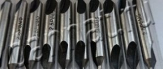
Main dimensions and characteristics of center drills
Each centering drill for metal must comply with the data indicated in the table:
| Indicator name | Size, mm | |||||||
| Working diameter | 0,5 | 0,8 | 1,6 | 2,5 | 4 | 6,3 | 8 | 10 |
| Landing diameter | 3,15 | 5 | 8 | 10 | 16 | 20 | 25 | 31,6 |
| Total length | 21 | 33,5 | 42 | 59 | 74 | 83 | 103 | 128 |
| Working length | 1 | 1,9 | 2,8 | 3,3 | 4,9 | 6,2 | 7,5 | 9,2; 11,5; 14,5 |
The roughness of the hole walls after surgery for drills with a cutting element radius of less than 0.4 mm is high. Therefore, they are used to drill holes in workpieces and parts that have high requirements for this indicator.
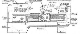
Application area
Centering drills for metal allow you to make holes in large quantities, which is why they are widely used in industrial enterprises. In the industrial sector, these tools are used to carry out operations for centering and metalworking parts on lathes, milling or drilling machines. They speed up the production process and reduce the cost of additional equipment. In addition, these tools are used in furniture factories, machine shops, engineering factories and car repair shops. Due to their perpendicular drilling, they have become frequently used in the woodworking sector.
Also, these metal-cutting tools are actively used in domestic conditions. They are used for drilling small diameter holes. The popularity of these drills in everyday life is due to their low price (their cost varies from 28 to 486 rubles) and ease of use. Also, centering drills, due to their high structural strength, are used at home to drill out stuck screws or self-tapping screws.
Nowadays, tools for creating centering holes are beginning to be introduced in the construction sector. Many craftsmen use them during countersinking - a procedure for processing the hole of a part to create countersunk heads to which fasteners of various building structures (rivets, screws and bolts) are attached.
Use in home workshops
In domestic conditions, combined centering drills are used mainly for making small holes and unscrewing stuck fasteners. In home workshops, designs with a diameter of 0.8 mm are used.
Before using this tool, it is necessary to perform its initial sharpening:
- Buy a tool for sharpening drills. Most often, electric machines with holes for drills are used to sharpen metal-cutting structures.
- Determine the diameter of the drill. To do this, you need to study the size tables, which indicate the diameter for each type of centering drill.
- Place the product in the appropriate hole in the electric machine. The sharpening process is carried out automatically, without human control.
- Remove the tool from the hole in the machine and clean it from excess chips and other types of contaminants.
If the geometry of the tool is disrupted during the sharpening process, the drill’s cutting speed and accuracy will decrease. This can lead to excessive heat generation and rapid wear of the product.
Also, before starting drilling, it is important to make a small recess of 3-5 mm in the part to center the tool.
The working area is located on the made recess. The procedure for making a hole should be done with a light feed and without unnecessary pressure. After the procedure is completed, the instrument is cleaned of dirt. For further use of the centering drill, it must be stored in closed containers (boxes or cases).
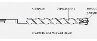
Device, design features
A center drill is a product consisting of cylindrical and conical parts. It is made from a single piece of metal, which has one or two working parts. The radius of the cutting element can be no more than 0.4 mm or higher than this figure, which affects the roughness of the surface obtained after the drilling operation. Products are distinguished according to the following parameters:
- designs (one- and two-sided);
- material of manufacture (alloy steel, carbon steel, high-speed steel, alloy);
- type (A, B, C and R);
- working diameter (from 0.5 to 10 mm);
- length (from 21 to 108 mm);
- landing diameter (from 3.15 to 31.5 mm);
- length of the working part (from 1.0 to 9.2 mm);
- hardness of the working part (from 63 to 66 HRC).
Centering drills are selected based on the specified classification and the requirements specified in the design drawings for the centering hole.
The combined centering drill is made in 4 types. This determines the scope of their application. Types A and B are used to produce center holes at an angle of 60°, and in the first case there is no safety cone, and in the second there is one, and its value is 120°. Type C drills are used to drill center holes at an angle of 75° without a safety cone, and type R drills are used to drill holes with an arc-shaped generatrix. The cutting tool drills strictly perpendicular to the surface with the highest precision, while sliding along the surface is eliminated during the operation.
Key technical requirements for drills
Centering drills must be made of high-speed alloys. According to GOST 14952-75, they must have the following parameters:
- The hardness of the working area should be from 63 to 66 HRC. For products made with cobalt or vanadium, the minimum and maximum hardness values increase by 1 HRC.
- The deviation limits of the dimensions of the centering tool should be in the range from 0.15 to 0.05 mm. The diameter of the structure cannot be less than 0.8 mm and more than 0.5 cm.
- The surface of the tool should not contain discolored spots resulting from excessive heat treatment of the cutting device during the manufacturing process.
After manufacturing the tool, manufacturers must check for functionality. The center drill is tested on parts made from steel whose hardness is 187-207 HB. After completion of the drilling procedure, a comprehensive inspection of the metal-cutting tool is carried out. The appearance and geometric characteristics of the product are considered. The sample being studied is compared with a reference product, the technical parameters of which are known. If wear or damage is detected, the tested sample is written off from production.