How much does a cutting cutter cost?
Turning cutters
| Name | Price | |
| Cutting cutter 40x25 T5K10 GOST 18884-73 | In stock | 494 rub. (VAT included) |
Bent scoring cutter | In stock | 100 rub. (VAT included) |
Bent scoring cutter | In stock | 128 rub. (VAT included) |
Bent scoring cutter | In stock | 176 rub. (VAT included) |
How to properly install a cutter on a lathe?
Why is the correct installation of the cutter on a lathe necessary and how to carry out the installation correctly? Basic rules, as well as some subtleties.
The entire course of the turning process on lathes from the very beginning until the final result is mainly determined by the correct installation of the cutter in the tool holder. Otherwise, if it is positioned incorrectly, the machine faces fairly rapid wear of the cutting edge.
It is also not uncommon for this problem to cause serious equipment breakdowns, which often entail significant material losses in production.
Before starting, you must first thoroughly clean the supporting surfaces of the holder. The main rule for installing a cutter on a lathe is essentially that its top must be at the levels of the machine center line.
Remember that setting below this line will lead to the part being pushed out of the centers when running, and setting above will lead to unacceptable heating and extremely rapid wear.
But in other cases, to further improve the performance of the cutter, minor deviations are allowed. For example, during the roughing process, the part is installed with a slight excess above the level of the centers, ranging from 0.3 to 1.2 mm (depending solely on the diameter of the workpiece).
A completely different case is finishing turning, in which the cutter is installed with a reduction by a similar amount.
Being secured in the tool holder with at least two bolts, the tool must be brought strictly to the center of the tailstock or headstock and adjusted in height, placing no more than three pads under it. This will give maximum accuracy when installing the part.
The linings themselves also deserve special mention: they should be prepared as a whole set immediately in advance. There is no need to replace them with pieces of metal or other materials.
The shims must be placed on the supporting surface of the tool holder, while controlling the overhang of the tool - it should not exceed 1.5 times the height of the rod, otherwise vibration of the part cannot be avoided during operation of the machine.
Further adjustment of the cutter to the required depth can be done in two ways: using the test chip method or with a cross-feed dial. When choosing the first technology, the cutter is brought close to the first contact with the surface of the rotating part.
After which it is moved to the right and then the cutting depth is set to the eye. If the diameter of the part’s groove is then larger than required, everything is repeated with a new cutting depth until the required result is obtained.
Video: adjusting (installing) cutters for a lathe.
Republished by Blog Post Promoter
Threading tools
Thread cutting using lathe equipment
Shaping on the machine is carried out by copying the working profile of the tool onto the part along a helical line. Translational movement is transmitted to the cutter, tap, die, comb. In combination with the rotation of the workpiece, a screw movement is obtained, the tool surface coincides with the cut surface.
As a rule, cutting small batches of fasteners and fittings up to M36 is carried out using taps and lechers. It is more profitable to produce large orders using specialized machines. Large-diameter threads, running threads, power threads, and precision threads are processed with cutters on universal lathes when CNC models are not available or the production program is insufficient.
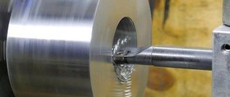
Cutting internal and external threads with a cutter
Threads with high coaxiality to other surfaces, transmitting movement and force are performed with a cutter. The rotation of the spindle is connected kinematically to the lead screw, which moves the support with the tool holder.
The general procedure includes:
- Grooving the surface along the length of the cut, forming a groove for the tool to exit.
- Selection, if necessary: sharpening, finishing of the cutter with checking using corner templates.
- Setting modes on the machine, tuning the guitar to a pitch not provided by the box.
The movement of the cutter per revolution of the workpiece is equal to the step P or the move H for multi-start ones.
- Installation of the cutter according to the template.
- Cutting for the number of passes selected from the directory.
Thread cutting of a batch of parts is divided into rough and finishing. For the latter, the tool is carefully sharpened. Threads with pitches greater than 2 mm are produced by lateral cutting. The left helical groove is obtained by switching the bit so that the lead screw rotates in the direction opposite to the spindle. The support with the cutter moves from left to right.
Average speeds when threading steel are 20–35 m/min with high-speed cutting tools, 100–150 m/min with carbide tools. Finishing strokes are performed at a speed increased by 50–100%. Internal threads are processed at 30% reduced conditions.
Using taps
The widespread grade R6M5 allows cutting workpieces with a hardness of up to 240 HB; taps made from tool alloy steels are used for “raw” parts. Carbide ones are rarely used, since the edges are chipped due to distortions and misalignment, which increase bending loads.
Installation of cutter
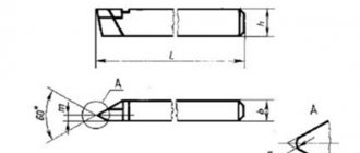
The tool is installed at an angle of 90 degrees to the workpiece being processed, in its center. A difference of a fraction of a millimeter leads to breakage of the cutter.
When turning brittle metals, the cutter is held at an angle of up to 10 degrees. Otherwise, the workpiece will break off faster than the cutter reaches the center. When working with high-speed tools made of solid metal, it is necessary to maintain a processing speed of no more than 30 mm per minute. Tipped carbide cutters operate at high speeds - up to 130 meters per minute.
Turning tool holders
alt=”Assorted turning tool holders” width=”” height=”” />A tool holder is a unit of a lathe, which is designed for fastening a cutting tool.
The quality of part processing largely depends on its accuracy. Therefore, several design options for this device have been developed, suitable for different conditions. In addition to lathes, tool holders are used in planers and some other metal-cutting machines, but there they have a different design.
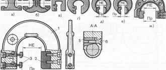
Conditional division
By design: — with an axis of rotation — with replaceable blocks
Division of toolholders with an axis of rotation: - with a horizontal axis of rotation (parallel to the spindle axis) - with a vertical axis of rotation (perpendicular to the spindle axis)
by source of position change: - mechanical (manual) - electromechanical - hydraulic - servo
For fastening the tool - with a wedge block - cutters 16x16, 20x20, 25x25 and 32x25 mm - VDI - fastening in a round hole in the position of the end surface of the tool holder disk with one bolt with a wedge. axis direction The most commonly used are VDI30, VDI40. The sizes VDI20, VDI50 and VDI60 are used relatively rarely. Can be used for static and driven tools - BMT - mounting in a round hole on the peripheral diameter of the toolholder disk. Fastening with four bolts. The most common are BMT-45, BMT-55, less commonly used are BMT-65, BMT-75. Can be used for static and driven tools
On a universal lathe, the tool holder is located on the upper slide of the support. The support also houses transverse and rotary slides, and the support itself is located on the longitudinal slide of the frame. The combination of these units allows you to move the cutter along all three coordinates and rotate it relative to the longitudinal axis, which provides a large number of accessible operations to the universal lathe.
For heavy grinding machines, the design of the support is somewhat different, since it bears a significant load. In such machines, the tool holder is located on an additional slide. This is required because the cross-slides of this type of machine are too massive and difficult to move manually.
Using the tool holder
The tool holder is a separate unit of the machine, secured with bolts. It greatly facilitates the processing of parts. The use of a tool holder is especially important when accurately boring holes. The designs of tool holders are highly durable and reliable, since even a small backlash can significantly reduce the processing accuracy.
The turning tool holder is designed to accommodate the cutter in height and in the horizontal plane. The height setting of the tool holder is of great importance for the machining process. If turning is performed, the cutter is installed so that the cutting edge of the tool is higher than the center line of the machine. For boring, the cutter is placed below the center line.
Simple tool holder
The simplest design has a tool holder called a “soldier”. This device has a spherical backing that allows you to quickly secure the cutter. By rotating the spherical spacer, the cutting angle and height position are adjusted. The cutter is secured using one bolt.
On the one hand, this device of the lathe tool holder makes it possible to install the cutter in a minimum time, and on the other hand, the entire load falls on one bolt, so it must be tightly tightened. However, in an attempt to provide sufficient clamping, this bolt is often overtightened, causing the thread to quickly become unusable. As a result, the bolt breaks or the internal thread is cut off. Repairing such a tool holder consists of replacing the bolts and boring the hole to a larger size. It is also possible to install a threaded bushing into the hole. To increase the durability of bolts, they are made from strong steels, such as 12ХН3А, subjected to carburization to a depth of 0.6-0.8 mm and hardening, which makes it possible to achieve a surface hardness of 50-60 HRC. Thanks to this, the durability of bolts increases by 10-15 times compared to raw bolts made from steel 45, however, their price also increases. For most of the tool holder parts, 45 steel is used, whose hardness is in the range of 220-260 HB.
Sharpening cutters
Sharpening of turning tools is carried out both during their manufacture and during wear. The sharpening process takes place on sharpening and grinding machines with continuous cooling. First, the main surface is sharpened, then the back and auxiliary. After this, the front surface of the cutter is processed until a smooth cutting edge is obtained.
Each cutter sharpening machine has two grinding wheels: one made of electrocorundum and one made of green silicon carbide. The first is used for processing high-speed steel cutters, the second is used for sharpening carbide cutters. To check the correct sharpening of the cutter, there are special templates.
Tools such as turning cutters are in fairly good demand and are widely represented in the catalog assortment.
Inverted cutting cutter
inverted cutter
Cutting work is especially difficult on amateur machines with low speeds and poor technical characteristics. You can resharpen a standard cutting tool, but this work is long and painstaking; the tool will turn out to be quite fragile, requiring extreme care in work.
To solve this problem, the design of an inverted cutting cutter was invented. These are tools with replaceable carbide steel inserts. They can be used in forward and reverse rotation. Moreover, the main mode for this tool is reverse rotation, when chips separate unhindered, they are easy to remove from the work area, and jamming occurs less frequently.
The design provides for height adjustment of the cutter using an insert triangle and a T-shaped profile of the cutting blades. This shape reduces friction during penetration into the material. The kit usually comes with 4 - 5 options for cutting blades. They can be sharpened many times as long as the length allows.
The long overhang of the cutting blade is very convenient, thanks to which you can cut off thick workpieces; it is advisable to lubricate them during operation. The tool is good for making narrow grooves, especially where the planes touch.