Methods for processing external conical surfaces
TO
category:
Turning
Methods for processing external conical surfaces
Next: Processing conical surfaces using a copying (conical) ruler
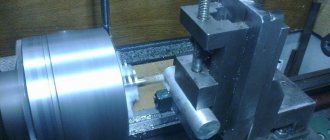
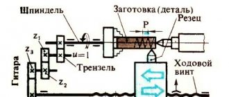
Machining conical surfaces with a wide cutter. Conical surfaces 20-25 mm long are processed with a wide cutter. To obtain the required angle, a mounting template is used, which is pressed against the workpiece, and a cutter is brought to its inclined working surface, then the template is removed and the cutter is fed to the workpiece. Machining conical surfaces with the upper slide of the caliper rotated. The rotating caliper plate together with the upper slide can be rotated relative to the transverse slide; to do this, the nuts of the screws securing the plate are released. The rotation angle is controlled with an accuracy of one degree according to the divisions of the rotary plate. The rotating caliper plate is precisely adjusted to the required rotation angle using an indicator based on a pre-fabricated part - a standard. The indicator is fixed in the tool holder, and the tip of the indicator is set exactly in the center and brought to the conical surface of the standard near the smaller section, while the indicator arrow is set to zero; then the caliper is moved so that the indicator pin touches the workpiece and the needle is at zero the entire time. The position of the caliper is fixed with clamping nuts. Advantages of the method: the ability to process cones with any slope angle, ease of setting up the machine.
Disadvantages of the method: the impossibility of processing long conical surfaces since the processing length is limited by the stroke length of the upper slide of the support (for example, the 1K62 machine has a stroke length of 180 mm); Grinding is carried out using manual feed, which reduces productivity and quality of processing. The processing of conical surfaces with the upper slide of the caliper rotated can be mechanized using a device. The flexible shaft receives rotation from the lead screw or from the machine's lead shaft through spiral gears and transmits the rotation to the screw handle of the upper slide.
Some lathes (16K20, 163, etc.) have a mechanism for transmitting rotation to the screw of the upper slide of the support. On such a machine, regardless of the angle of rotation, it is possible to obtain automatic feeding of the upper slide. If the outer conical surface of the shaft and the inner conical surface of the bushing must mate, then the taper of the mating surfaces must be the same. To ensure the same taper, processing of such surfaces is carried out without readjusting the position of the rotary plate. In this case, to process a conical hole, a boring cutter with a head bent to the right from the rod is used, and the spindle is rotated in reverse. Machining of conical surfaces using the tailstock displacement method. Long outer conical surfaces are machined by shifting the tailstock housing. The workpiece is installed in the centers. The tailstock body is shifted in the transverse direction using a screw so that the workpiece becomes “skewed.” When the support carriage feed is turned on, the cutter, moving parallel to the spindle axis, will grind the conical surface.
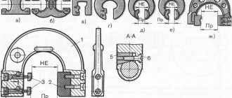
1. PROCESSING THE CONICAL SURFACE OF A CONE WITH A WIDE CUTTER: a - installation of the cutter according to the template, b - processing diagram
2. PROCESSING OF CONICAL SURFACES (CONES) WITH THE UPPER SLIDE OF THE CALIPER ROTATED: a - turning the outer surface, b - boring the inner surface, a - the inclination angle of the cone
3. DEVICE WITH A FLEXIBLE SHAFT FOR MECHANICAL FEED OF THE UPPER SLIDE WHEN PROCESSING CONICAL SURFACES (CONES): 1 - handle of the screw of the upper slide, caliper, 2 - flexible shaft, 3 - device body. 4 - gear transmission
The amount of displacement H of the tailstock is determined from the triangle LAN:
4. PROCESSING OF CONICAL SURFACES (CONES) WITHOUT READJUSTING THE UPPER CALIPER SLIDE
5. PROCESSING OF THE OUTER CONICAL SURFACE (CONE) BY THE METHOD OF DISPLACEMENT OF THE TAILSTOCK: N - the amount of displacement of the tailstock
The amount of displacement of the tailstock body relative to the plate is controlled by the divisions at the end of the plate or using the cross-feed dial. To do this, a bar is fixed in the tool holder, which is brought to the tailstock quill: the position is fixed with a dial. Then the transverse slide is moved back to the calculated value along the limb and the tailstock is shifted until it comes into contact with the bar. Setting up the machine for turning cones by displacing the tailstock can be done using a reference part, which is fixed in the centers and the tailstock is shifted, monitoring with an indicator the parallelism of the forming surface of the reference part to the feed direction. Control can also be carried out using a cutter and a strip of paper: the cutter is in contact with the conical surface along the smaller and then larger diameters so that a strip of paper is pulled between the cutter and this surface with some resistance. To prevent damage to the center hole during rotation of the workpiece, a ball center is used. Rotation of the workpiece must be transmitted only by a clamp: fastening in a chuck is unacceptable. The advantages of processing conical surfaces by displacing the tailstock: the ability to process long workpieces and the ability to automatically feed the caliper.
Disadvantages: inability to process internal cones and cones with a large angle.
General concepts about taper
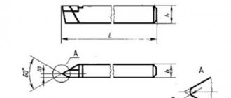
The surface of the cone consists of the following quantities (Fig. 1): section D is larger and section d is smaller.
Between the two surfaces formed by sections D and d, there is a distance I. α is the slope angle of the cone, 2α is the angle of the cone. Rice. 1. Cone geometry
The ratio K=(D – d)/I shows the taper of the object. When written, it is indicated with a division symbol or a decimal fraction. For example: 1:20, 1:50 or 0.05, 0.02.
The relation Y=(D – d)/(2I) = tanα is called slope.
Machining taper surfaces
In production, it is often necessary to process shafts that are structurally designed with conical transitions between the diameters of the journals. If the length of the conical surface is no more than 50 mm, it is ground with a wide cutter. In this case, the cutter must have a cutting edge inclination angle similar to the cone angle on the manufactured product. The feed movement with the cutter is transverse.
To reduce the deformation of the plane forming the cone and eliminate errors affecting the inclination angle of the cone, the cutting edge of the cutting tool is fixed along the axis of the workpiece. If the cutting edge of the cutter is longer than 15 mm, harmful vibrations occur during processing.
Vibrations increase under the following conditions:
- increasing the length of the workpiece;
- reducing the diameter of the workpiece;
- smaller cone slope angle;
- close distance of the cone to the center of the workpiece;
- increase in cutter overhang;
- weak fixation of the cutter in the normal position.
Exposure to harmful vibrations negatively affects the quality of processing. Traces, unevenness, and roughness appear on the surface. By using cutters with a wide cutting part, vibrations are avoided. In this case, the radially directed cutting force can disrupt the cutter settings, changing the slope angle.
Cones with significant inclinations are processed by turning the upper slide of the support and the cutter holder at an angle α (Fig. 2). It is equal to the angle of the cone that is being machined. The handle of the slide moves the cutter. Manual feeding has its disadvantages. The main one is uneven movement.
Sometimes this causes roughness to appear on surfaces. The purity of processing depends on the qualifications of the performer. This method is suitable for cones with lengths equal to the stroke of the upper slide.
Rice. 2. Machining the conical surface by turning the upper slide of the caliper:
2α – cone angle; α – angle of inclination of the cone
By shifting the tailstock of the machine, conical planes with an angle α=8...10˚ and increased lengths are processed (Fig. 3).
Rice. 3. Machining the conical surface by shifting the tailstock:
d and D – smaller and larger diameters; l – distance between planes; L – distance between centers: h – rear center offset; α – cone slope angle
H=Lsinα.
If the angles are small, sinα ≈ tanα.
h≈L(Dd)/(2I), where L is the gap between the centers, D is the large section, d is the small section, I is the gap between the surfaces.
If L=I, then h=(Dd)/2.
The tailstock shift is controlled by a graduation on the edge of the support plate opposite the flywheel. There are also marks on the end of the tailstock. Each division is equal to 1 mm. If there is no scale, the shift is calculated using an ordinary ruler, which is applied to the support plate.
To achieve compliance with the taper for the flow of products processed by this method, the parameters of the parts and the alignment holes must have a minimum of errors. Shifting machine centers during operation provoke wear in the centering holes of the workpieces.
It is recommended to first process the planes of the cones, then correct the holes for alignment. At the end, finally grind the workpiece in a finishing manner. To avoid breaking the alignment holes and reduce wear on the centers, it is advisable to work using a rounded point.
A regularly used method for processing conical planes is copiers. Plate 7 with copy ruler 6 (Fig. 4) is fixed on the frame. The slider 4 moves along the ruler. It is connected to the caliper 1 by a rod 2 using a clamp 5. In order for the caliper to easily move across, the cross-feed bolt is unscrewed.
From the movement of support 1 along the machine, the cutter acquires double movement: across behind the ruler-copier and along behind the support. The movement in the transverse direction is affected by the angle of rotation of the ruler 6 relative to the axis of rotation 5. The rotary angle of the copier is controlled using the scale of plate 7, securing the ruler with screws 8.
The cutter is fed to the required cutting depth using the handle for moving the caliper slide at the top. External conical planes are processed with passing cutters.
Rice. 4. Processing of a conical surface using copying devices:
a – with longitudinal movement of the caliper: 1 – caliper; 2 – traction; 3 – clamp; 4 – slider; 5 – axis; 6 – carbon ruler; 7 – plate; 8 – bolt;
b – with transverse movement of the caliper: 1 – device; 2 – copier; 3 – carbon roller; 4 – internal conical surface; α – angle of rotation of the tracing ruler
Shortened Morse tapers
In the process of development of machine tool building, machines appeared in which the dimensions of the tool chucks turned out to be smaller than the length of standard Morse tapers, which created great problems with selecting a tool and installing it in the machine. For such machines, a separate type of shortened Morse tapers was developed.
The main feature of such cones is that while maintaining a larger diameter and taper, the length of the shank has been reduced. At the same time, shortened cones, thanks to maintaining their shape, are in no way inferior to standard ones. They allow you to securely fasten the tool and just as quickly replace it.
Methods for making internal conical planes
Inside the part, the selection of conical planes 4 (Fig. 4) is carried out using a copier 2, which is fixed into the tailstock quill or into the turret. In the cutter holder of the transverse support, a device 1 is attached, which has a roller for copying and a pass-through cutter with a pointed profile.
When the support moves in the transverse direction, the copy roller 3 corresponding to the profile of the copier 2 moves in the longitudinal plane. Through device 1 the movement is transmitted to the cutter. Inside conical surfaces, processing is carried out using boring cutters.
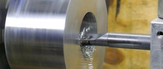
To obtain a hole with a conical configuration in metal with a solid structure, holes are drilled, bored, and reamed in the workpiece. Further processing is carried out using sets of conical reamers. The cross-section of the pre-prepared hole should be 0.5...1 mm smaller than the lead-in cross-section of the reamer.
When making a high-precision conical hole, before reaming, processing is carried out with a conical countersink. For this purpose, a hole with a cross-section 0.5 smaller than the finished cross-section of the cone is drilled in a metal with a solid structure and processed with a countersink. The countersink allowance is reduced by using step drills with different sections.
How to process center holes
The cycle of manufacturing and repair of shafts provides for the presence of central holes at their ends. These technological recesses are necessary for high-quality fastening and avoiding beating when the shaft rotates. Center holes are made especially carefully, using high technology.
The alignment holes are located strictly on the same axis. Both conical holes at their ends must be absolutely the same size, whatever the cross-sections of the journals at the edges of the shaft. Otherwise, the quality of processing decreases and wear on the alignment holes increases.
Rice. 5. Center holes:
a – unprotected from damage;
b – protected from damage
A sample of central holes is shown in Fig. 5. The most popular alignments are those where the cone angle is 60˚. When making heavy shafts, holes with angles of 75˚ or 90˚ are used. To avoid the apex of the center from resting on the workpiece, cylindrical recesses with a diameter of d are machined in the central holes.
The chamfer, made at an angle of 120˚, protects the center holes, which are used many times, from damage and holes (Fig. 5, b). Center holes of small parts are processed in various ways. The shaft blank is mounted in a self-centering chuck; a drilling chuck with a centering tool is placed in the tailstock quill.
A drill for cylindrical holes is used to perform the initial stage of manufacturing center holes of large cross-sections (Fig. 6, a). Subsequent processing steps are performed with a single-tooth (Fig. 6, b) or multi-tooth countersink (Fig. 6, c). Center holes with a cross section of 1.5...5 mm are made using combination drills. They can be either with a safety chamfer or without it (Fig. 6, d, e).
Rice. 6. Center tools:
a – cylindrical drill; b – single-tooth countersink; c – multi-tooth countersink; d – combination drill without safety chamfer; d – combination drill with safety chamfer
When processing the shaft for the manufacture of center holes, it is subjected to rotation. Feeding is carried out manually. The end to be machined is pre-cut using a cutter. The size of the centering recess is controlled with tools: a quill scale or a tailstock flywheel dial.
By preliminary marking on the shaft, the alignment of the manufactured center holes is achieved. If the workpiece is long, it is supported with a steady rest during centering. The center holes are marked using a square. Having marked the workpiece, mark the places for the center holes.
Shafts with neck sections not exceeding 40 mm are punched using a special device (Fig. 7), without using preliminary markings. Housing 1 is placed on the end of shaft 3 with one hand. By hitting the center punch 2 with a hammer, the center of the hole is marked.
Rice. 7. Device for punching center holes without preliminary marking:
1 – body; 2 – center punch; 3-shaft
Center holes with uneven wear or damage are corrected using a cutter. To carry out the operation, the machine support carriage, located on top, rotates through a cone angle.
Types of cones
Morse can be manufactured using different technologies, so it is not always possible to replace one tool with another without problems.
Before selecting a suitable fairing, you need to decide what dimensions the Morse cone has that correspond to GOST.
Tools often differ from each other in length, diameter, and angle.
When choosing a fairing, you need to pay attention to the letters and numbers:
- the number opposite the letter “D” means the basic size of the cone socket;
- the number next to “L” is the penetration depth.
These sizes are common to all countries where the metric number system is actively used. Morse fairings created today, as a rule, have adapters that can be changed. This simplifies the work, since the equipment can be combined with different standards.
Capital letters of the Latin alphabet indicate features of the flange section. The proluvium itself can have a length from 2.5 cm to 16 cm.
Today, the highest quality fairings for drilling machines can be considered tools that are produced under the brands “Kennametal” and “Kapto”.
Those who work on the machine know very well that they have good resistance to sudden and significant changes in temperature. The cones of these brands are quite durable and easy to use. They meet all the necessary requirements. Morse codes, which are marked "Capto", are released and distributed throughout the world.
https://youtube.com/watch?v=evWPoMxRr-Q
Today, such instruments are promoted as high-end analogues of HSK. The fairing itself, when projected onto a plane, will have the shape of a triangle. There are indentations on its round edges. But it should be noted that such a tool has a rather high price, since its manufacturing process is very complex. In turn, Kapto are divided into several types, the most popular among which are those designated as “C3” and “C10”.
Initially, such a tool was created so that it could be used for clamping using the collet method.
There is a division into 8 sizes: the smallest of them is designated as “KM0”, and the largest is designated as “KM7”. All other types of cones are also designated by the letters “K”, “M” and a number from 1 to 6
. However, the Russian standard does not recommend using the KM7 Morse fairing; instead, a metric cone No. 80 is used.
Fairings that are designed to both inch and metric standards can be interchanged. They are similar in every way and differ only in the thread of the shank.