05.06.2020
The machine allows you to process parts for a wide variety of purposes. Modern universal models have many parameters, with the help of which work with products is carried out without difficulties. But this tool also has a vulnerable aspect - interaction with objects of inappropriate shape. A lathe chuck faceplate is an easy solution in situations like this.
Large products do not fit into the machine itself, so it is impossible to secure them in the required position. As for non-standard shapes, usually the clamping device, which acts as a fastening element, damages them. Squeezing is not very good for flat materials, the edges may crack or bend. It is especially unpleasant when various fittings are located in these places. And the object itself is quite capable of being damaged in such a situation. Accordingly, it is strictly not recommended to start processing without a specialized adapter.
Why do you need a faceplate on a lathe: purpose
When you have to work with metal products, the first thing you need to do is securely secure the workpiece so as not to damage the surface and also not to injure yourself. Each equipment has its own locking devices, but they have significant limitations on their use. Turners using standard equipment can only process certain blanks that have a small diameter and a regular shape. But if for some reason it cannot be placed in the cartridge, then fastening is done using a special washer. This is usually required when the workpiece:
Advice and recommendations from experts
The faceplate is a widely used device in metalworking and woodworking. Due to the fact that it is intended for the production of non-standard parts, the tasks before them can be very diverse. Therefore, during production, it is necessary to take into account many nuances.
From this it is clear that specialized stores have a huge number of faceplates. Sometimes even this is not enough. In this case, turners make them themselves, focusing on their own needs and requirements for a given faceplate, which helps to tailor it to a specific production goal.
It is important to always have a whole set on hand, including faceplates for various purposes. However, some of the kits may be homemade. It happens that some variations may not be available on the market or in the assortment of a specialized store.
Operating rules
Let's briefly go through the main nuances of how to install and work with such an element, depending on the equipment.
On universal
In principle, what is a faceplate for a metal lathe chuck? It is an adapter with a special type of clamps. But at the same time, he himself is placed on the base according to different laws.
- An uneven surface, asymmetrical, always implies mounting on a clamp.
- To straighten the axle, you need to use lifting bars.
- Use a counterweight (usually included) to avoid vibration.
On rotary turning machines
There are fundamental differences here. If we constantly mentioned above that the washer is simply an additional adapter designed to simplify work with unusual workpieces, in this case it is the main element of the fastener. After all, the machine itself is a round table, on top of which a disk with several bushings is placed. Objects are mounted on them. What’s interesting is that even if the bushings themselves break or become unusable, they are replaced separately. And it becomes a kind of working surface that cannot be changed.
Read also: Orbiz, what is it and what is it for?
Self-centering washers
This is one of the most common types of nozzles. The main differences are that there is a large hole in the center of the surface. It is the same size as the bushings around the perimeter. The main task is to seal the contact with the shaft in order to increase the level of reliability and service life of the equipment.
Design
It makes no difference which machine is used: metal or wood. This device for securing objects is suitable in both situations. The most common discs are made of steel and cast iron. Grooves and recesses are made on them. The main goal is reliable fixation of the object. Depending on which grooves are located on the surface, there is a certain list of shapes with which a given fastener is allowed to interact.
In addition, the equipment itself is often connected to the spindle using hubs. But the models that are mounted on the cartridge are easy to distinguish. The hubs do not look like cones, they are strict cylinders.
In many variations, the size of the faceplate allows you to install additional clamps on it. Usually clamp type. Then the future product is clamped according to the principle of a vice if it has protruding parts that ignore the mechanical compression pressure.
Do not forget that atypical processing is always a certain risk. The manufacturer did not intend such an action, which means there is a possibility of destruction of the product upon startup. And also the scattering of fragments over a large area. Accordingly, the main weapon in this case is a thorough balance check, calculation, and test run. Theoretically, a danger also arises for the equipment; it can be damaged if the fasteners are set inaccurately.
Attention and caution are the main rules that must be followed.
Types and purpose of washers
This is not a universal device. Hence the large number of varieties, each of which is used for fastening packages of different shapes. In some cases, several types are used at once.
T-slot disc
From the name it becomes clear that the device has grooves cut out in the shape of the letter “T”. Exactly the same ones are present on the tables of milling machines. On different devices, the grooves are located at different frequencies, hence the variety in their number.
It is into these grooves that the fastening nuts are inserted so that they do not interfere with the contact of the workpiece and the faceplate. At the bolted location, special stops can be used. They are also located in grooves.
Specifications
The design of the faceplate is suitable for machines not only of wood, but also of metal. It is presented in the form of a disk with workpiece assemblies made on it. The materials can be either cast iron or steel. Other materials are used in rare cases.
Tapered hubs and threaded holes serve as a tool for attaching the tooling to the spindle. Specific parameters are selected for certain dimensions of the output end of the shaft. Provided that the fixture, which is clamped directly into the machine chuck, is provided with a cylindrical hub.
The workpiece is secured using clamps, crutches, various clamps and other clamping devices. For this purpose, a lathe chuck is installed and used. It can be assembled on a faceplate either along the axis or with its offset. It is worth paying special attention to the faceplate when using production safety precautions.
Large dimensions, non-standard fastenings and non-cylindrical shape of surfaces pose a serious danger both to the turner himself and to others. At the beginning of work, it is necessary to balance and secure all the elements so that the structure does not fluff up and individual components do not fly apart.
Improvement of technical parameters
Tuning to increase power
The design of the motorcycle engine allows for tuning to increase its power. One option is to re-press the engine crankshaft and change the support bearings. Usually, secondary shaft bearings from a Java motorcycle were installed as new bearings. This restoration made it possible to achieve an increase in engine power of the IZH Planet - 5 by 10-15%.
The next option for adding power was to increase the cylinder volume. For this purpose, its upper part was cut off and the sleeve was bored to 76 mm. Then the appropriate piston was installed, usually a piston from a Planet Sport motorcycle was used.
Increasing motorcycle speed
After this operation, the speed of the motorcycle increased, according to some sources, to 160 km per hour. Therefore, work to increase engine capacity was carried out by owners who planned to operate their vehicle mainly on highways.
The most difficult technical tuning option for adding power to the IZH Planet - 5 is the installation of supercharging. For this purpose, an exhaust valve is installed, the device of which corresponds to the analogues on the sports versions.
Then an exhaust resonator is installed, which has sharply directed parameters. Its task is to create a wave backpressure of the fuel mixture. Next, a spool valve is installed to obtain asymmetrical phases of engine operation, which avoids the direct release of the spent mixture.
Performing supercharging on the engine of the Fifth Planet is a rather complex process and therefore is not widely used.
Improved grip
As engine power increases, it is necessary to carry out work to improve the clutch. Under standard conditions, the standard clutch works reliably.
Varieties
Due to the widespread use of faceplates, it has a large number of modifications, mounting options, etc., therefore, a large number of types.
Universal and special
Typically, such faceplates are a mixture of several of the above types. Such faceplates are created for working with more complex parts, but even they are not always suitable for them, which is why it is modified to the required parameters.
Part with squares
When processing products with low rigidity, modifications with squares are used. The workpiece in such devices is mounted on a separate flat or prismatic base.
The base is made in the form of an angle, its second edge is attached to the surface of the washer. To ensure the integrity of the workpiece, fastening is provided at several points over a large area.
Leashes
Such faceplates have two T-shaped holes, in one of which there is a leash, and in the other there are clamps. The part is attached to the surface with screws in the center. In addition, T-shaped grooves are responsible for fastening.
With holes
This faceplate has a special design in the center for threaded connection to the spindle. The part has 3 holes for clamps.
Sometimes washers are attached to homemade bushings by welding. This is done for a more durable fixation; however, models with an already modified design are sold.
T-slots
On the surface of such equipment, T-shaped grooves are made, similar to those used on tables of milling machines. Special stops or fastening nuts are inserted into the grooves. During processing, the product is pressed to the plane with screws.
The design of the device makes it possible to fasten almost any product. The grooves on the surface of the disk are usually located orthogonally. Depending on the purpose, the number and frequency of grooves change.
With through grooves
Basically, these faceplates are needed for fastening irregularly shaped parts. There are several holes on it, some of them are through, and some are not.
This type does not have a certain number of recesses. Some of them are in grooves. The disk also has stiffening ribs that are mounted.
Types of faceplates
Today, there are several classifications that divide existing faceplates into groups according to different criteria. So, among the common faceplates on the market, the following types are distinguished:
- Smooth;
- With regular threaded holes;
- With radial or classic, circular, threaded holes (grooves);
- Faceplates with a leash.
Since each type has its own characteristics, it makes sense to dwell in a little more detail on each type.
According to the regulatory document GOST 4082-69, special requirements are imposed on faceplates made of steel, for example, their tensile strength must be at least 4.9 MPa.
This approach to manufacturing materials is easily explained:
- Cast iron is little susceptible to thermal changes;
- This material is easy to process;
- The cost of cast iron is very low compared to other materials of similar quality.
Smooth faceplates
The most common type of faceplate is smooth; in the vast majority of cases it is used when it is necessary to process a part in the form of a regular or stepped ring . Thus, the faceplate, already installed in the structure of the lathe, is necessarily centered using a surrounding element located on the flange.
The workpiece being processed is secured using special clamps or through a central clamp , which ensures reliable installation of the part and its immobility. Clamps are usually used with the simplest possible design in order to eliminate any risks, because they consist of a screw, two washers and a nut, which, when connected, provide an excellent level of fastening.
If fastening must be done using squares or special racks , and only a smooth faceplate is available, then the fastening procedure is slightly different: after centering the faceplate, the square is installed directly on it .
It should be noted that centering should be carried out as responsibly as possible, since otherwise the imbalance will negatively affect the service life of the spindle.
Faceplates with threaded holes
The fundamental difference between such faceplates and the previous type is the presence in the hole, which is located in the middle of the faceplate, and a thread, which is intended for mounting it on the shaft of a lathe . Accordingly, in this case, the faceplate acts as a kind of substitute for the flange, since fastening to the upper end of the spindle is carried out directly without any intermediaries.
Moreover, such faceplates are often equipped with several holes (usually three), into which clamps (which are sometimes called “cams”) are screwed, necessary for additional fastening of smaller workpieces.
Sometimes faceplates can be put on threaded bushings made independently by employees of certain enterprises. Such bushings can either be welded onto the shaft or soldered. Similar parts are produced to increase the reliability of fasteners, but the vast majority of experts agree that faceplates with existing threads are more reliable.
Faceplates with radial and circular grooves
The faceplate with radial grooves is radically different from those listed above:
- firstly, threaded through grooves are connected into groups , which are separated from each other by special grooves,
- secondly, the faceplate can be either threaded or without .
The number of threaded grooves can vary, and there are also faceplates in which their number varies sharply (for example, three in one group and six in another). The grooves can also be located in the grooves themselves, but it is not at all necessary that all of them be through, some can only reach half of the part.
The main purpose of radial grooves is to fix a non-standard-shaped workpiece using screws during processing. Stiffening ribs can be additionally screwed onto the rear side.
Stiffening ribs are installed to increase the potential impact on the part: since classic, factory faceplates are devoid of them, representing a solid piece of metal or alloy, their strength and “durability” is achieved by increasing weight.
There is even a special requirement for cast iron faceplates - their thickness must be at least 5 mm).
Drive faceplates
Drive faceplates (which are sometimes called gear plates) differ from those described above in design: for example, in the body of the part there is a straight T-shaped profile cut where the drive is located (in it, by the way, there is another T-shaped groove, which is parallel to the first and where the clamps).
The clamping elements, which can be adjusted with the appropriate screws, also have T-shaped grooves, where the cams are already located, providing direct fastening (they are able to move freely along the groove, therefore they are already installed on the surface of the workpiece).
The principle of operation is quite simple: the workpiece is installed in the center, after which the clamping elements moved towards it from several sides and the cams are additionally placed on its surface , their task is to additionally cover the workpiece.
additional reliability in use is ensured by the presence of T-shaped grooves located in the clamping elements. This makes it possible to process even multi-stage workpieces.
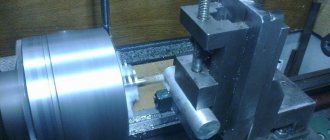
Fastening the part to the faceplate
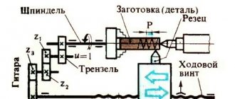
The part is fastened to the faceplate using various auxiliary elements, which are designed to additionally hold the part. If it is possible to install the part symmetrically, use a “corner”, which is placed in the middle of the faceplate, and the workpiece is already attached to it. It should be remembered that the more symmetrical and balanced the part is located on the faceplate, the better its processing will be performed . An example of such an installation is shown in the figure below.
As you can see, just above the spindle with the tip there is a round part - a counterweight , which is necessary when working with:
- Weighty workpieces;
- Workpieces center of gravity is greatly shifted relative to the central axis;
- Severely irregularly shaped workpieces.
installation of the counterweight is carried out for each specific part; its mass and position on the faceplate are first calculated.[/warnin]
Asymmetrical parts are attached to the faceplate in several stages:
- Firstly, it is necessary to install racks that will “hold” the part from several sides at the same time. The racks must be parallel to the axis of the faceplate, otherwise the workpiece may fall out.
- Secondly, the clamping elements are placed as close to the workpiece as possible . Finally, the correct installation is ensured using a surface planer.
Description of design
Once again, the faceplate for a wood lathe is presented in the form of a cast disk made of metal, which has a so-called central threaded hole, designed for fastening it on a wood lathe, or rather on its spindle. In it, the workpiece is carefully secured using metal screws that pass through its holes and are firmly screwed into the wood.
When sold, a woodworking lathe is equipped with a faceplate having an outer diameter of 100–150 mm. If there is a need, then it is possible to additionally buy a faceplate for a wood lathe of any size, with a different location of the mounting holes, as well as a working thickness.
How to make a homemade mini wood lathe with your own hands
A simple homemade lathe can be made from scrap lumber and a few old parts. Making a woodworking machine will not be difficult, and you need the most common tools; these can be found in any household. And how many pleasant little things will come out of the incisor!
Small machine for home
almost finished machine and faceplate We present a mini-lathe with dimensions of 800 x 400 x 350 mm. On it, they process parts with their own hands up to 25 cm in diameter and up to 40 cm in length.
Design elements:
- electric motor from the pump;
- front pillar - high-power electric sharpener for a couple of stones;
- caliper with support and adjustment;
- the frame is welded from a metal profile;
- the rear pillar is an element of a drill.
You will need plumbing equipment:
- electric drill;
- angle grinder;
- file;
- welding machine.
It is necessary to purchase additional materials:
- metal corner and channel;
- piece of block, plywood 10 mm;
- two pipes with such diameters that they are placed coaxially;
- metal strips 20 and 40 mm;
- fasteners;
- drive belt (from the car).
Assembling a homemade lathe:
- Choose a sharpener with your own hands so that you can use it without modifications. The axle must be placed high, with sealed bearings and washers to secure the discs. We install disks for adjusting the speed of movement on one of the axis outputs, and a faceplate for the workpiece on the second.
- The bed consists of two parallel channels, between which there is a gap - a guide. The length of the guide is equal to the length of the workpieces. At one end we weld a channel in the shape of a P, on which the headstock will be installed. The second end can be closed with a corner.
- The machine support is a stand of two pipes inserted into one another to adjust the height. At the desired height, the structure is fixed with a bolt. A horizontal bar is welded as a stop. Weld the stand with your own hands to the base using two corners secured to the guide using a pressure plate and a bolt with a nut. To correctly select the rotation speed of the part, use the drawing. It is most convenient to take a pair of intersecting values. For smaller jobs on particularly hard wood, you can remove the belt and use just the sharpener motor. That is, it is possible to work with several rotation speeds.
- The drive pulley is made from an old drill chuck. The driven pulleys are cut out of thick plywood, glued in two layers. We also make the faceplate from plywood; we pre-cut holes in it for the self-tapping screws that will hold the part. The faceplate is screwed onto the front pillar axle with the part already attached.
- We install the metal base on two supports. On the side of the headstock we make a platform of thick plywood on which the electric motor will be placed. To be able to change the belt tension, the motor is attached to a small plate, which can be moved around the site and secured in the right place.
caliper and tailstock relationship between rotation speed, part diameter and material hardness
Simple tabletop mini machine
very simple, but gets the job done. The second homemade mini-structure consists almost entirely of wood, so the following is used in its manufacture:
- screwdriver;
- hacksaw;
- sandpaper;
- jigsaw;
- pliers.
And materials:
- board No. 5 is better than oak;
- two dies for parquet;
- screws No. 45, about 10 pieces;
- construction dowel;
- aluminum plate;
- electric motor (can be from an old VCR);
- shaft from an old cassette player;
- thick bicycle spoke or pin;
- bolt and nut.
Assembling a lathe with your own hands.
- We saw off a piece of board 30 x 15 cm to create a base.
- We cut out two sections lengthwise from the parquet blocks: one with an outer groove, the second with an inner one. We drill one hole for self-tapping screws 5 cm from the ends. The length of the die will be equal to the future workpiece.
- We screw the parquet slats to the base with the grooves inward, and we get guides. There should be a whole parquet floor between them.
- We will make the tailstock from parquet, about 10 cm high, choosing a notch in the middle. In the lower part we cut out a wide hole into which we glue the nut. Subsequently, a bolt will be screwed into the nut to secure the rear strut.
- We attach a block to the tailstock, onto which we fix the dowel using a metal plate.
- The support for the cutter will be made from a knitting needle bent into the shape of a long bracket located along the bed. We fasten it with a couple of screws.
- The headstock is a block of wood onto which an electric motor is screwed using a metal bracket. When fastening, use thin rubber gaskets that reduce vibration. Before final fixation, you need to align the front and rear centers.
- You can make a faceplate with your own hands from a plastic washer, which we glue onto the shaft with hot-melt adhesive. We fuse several sharpened pins into the faceplate to secure the workpiece.
The mini-machine is ready to use. The electric motor needs to be taken at 12 W and connected through the computer power supply, then the power is enough to process small wooden parts.
Thus, making a simple lathe with your own hands will not be difficult. Video about a homemade machine with a 125 W washing machine motor:
Main types of equipment
Most lathes are used to work with the external and internal surfaces of parts of various shapes, including conical, cylindrical and shaped.
Various types of machines also allow drilling holes and processing ends. Now let's talk about what types of devices are available today. The main classification of lathes is based on their purpose, the functions they perform and design features.
1. Screw-cutting lathes. They are universal and designed to perform a large number of operations. It is also important that they provide a high level of accuracy. This type of equipment is also required for thread cutting.
The first types of screw-cutting lathes appeared quite a long time ago. Over time, their design improved, they became more and more functional and perfect. The most modern models are equipped with CNC - numerical control. This function allows you to set basic operating parameters, after which the automation will monitor their compliance without human intervention.
When choosing a model of a screw-cutting lathe, it is important to take into account its main characteristics:
- Maximum spindle head rotation speed, as well as the ability to fine-tune it.
- The diameter of the rod installed in the hole.
- Torque.
- Rated power.
- Number of feeds of longitudinal and transverse type.
- Possibility of cutting various types of threads.
All these characteristics depend on the design of the screw-cutting lathe and its type. You should buy such equipment only from trusted sellers - official dealers of large companies.
2. Vertical lathes. Devices from this group are designed to work with workpieces with large weight and diameter, but with low height. This category includes elements of turbines and generators, flywheels, gears, and so on. They are used for surface and end processing, grooving and milling, and can also perform grinding and threading.
Unlike other types of machines, in these devices the main movement is made by the faceplate, and the input is carried out by the supports. Most modern machines are equipped with a CNC function, which allows you to automate a significant part of the work.
3. Lathe machines. The main purpose of this type of lathe is to process parts that are bodies of rotation. However, they are best suited for working with workpieces of large diameter, but with limited thickness. This category includes, for example, wheels, gears, flanges, and so on. Lathes are designed for processing ends, threading, boring internal surfaces, and so on. The axis of rotation in these devices is located in the horizontal plane.
Lathes are practically not used in modern production. For the most part, they were replaced by rotary turning machines. Lathes today are more often used in workshops for the production of single products with large dimensions and repair work.
- Faceplate for a lathe in Moscow
4. Turret lathes. They are designed to work with parts made of calibrated rod. They are distinguished from universal lathes by the presence of a turret - a special holder for the tool. Because it can be calibrated during operation, many parts can be produced in one setup. In this case, there is no need to reconfigure the machine. Modern models of these machines allow you to install up to 12 tools in the head. As a result, they can be used to perform almost all types of processing:
- Boring.
- Countersinking.
- Drilling.
- Shaped turning.
- Thread cutting and so on.
5. Turning and milling machining centers. As the name suggests, they combine the functions of lathes and milling machines. The center includes a milling head, which makes these machines direct competitors to turning-turret machines in terms of the large number of operations performed:
- turning;
- milling;
- chiselling grooves;
- grinding;
- drilling holes;
- thread cutting.
Due to their advantages, machining centers can be considered one of the most promising developments. All main models are equipped with CNC, which allows you to automate most turning operations. The disadvantages of this type of equipment include the fairly high cost and serious requirements for the qualifications of specialists.
6. Automatic longitudinal turning machines. Their main task is the production of serial products from rods made of various grades of steel, aluminum, and copper. They allow you to perform various types of turning and milling work with a tolerance of no more than 0.1 mm. The machines can process round and hexagonal bars, as well as shaped profiles and wire. There are various types of these devices in which movable and stationary spindle heads are installed. The devices can be single-spindle or turret. The latter are distinguished by a wide range of functions and can carry out various operations without recalibration.
7. Multi-spindle lathes. These devices can also perform a full range of operations and are designed to work with workpieces formed from rods or pipes. They have high power and structural rigidity, and can perform various operations simultaneously. This type of machine is classified as expensive and is usually used by large enterprises to ensure mass production.
The listed types of devices are among the most common and are found in most enterprises. Of course, there are other types of lathes, but it is impossible to describe them in one article.
Before summing up, it is important to note another classification of equipment based on technological features.
1. Tabletop machines. They, as the name suggests, are fixed at the specialist’s workplace. Of course, this category includes devices that are small in size and weight. With their help, you can perform all main types of turning operations, including boring, milling and others. Of course, in terms of productivity, they are inferior to stationary options and are more often used by small companies than by large manufacturing firms. They are often used in everyday life due to their fairly modest energy consumption and affordable cost.
2. CNC machines. We have mentioned them several times in the article, but we would like to consider them separately. These machines have a higher cost and place higher demands on personnel qualifications. At the same time, almost all large enterprises are switching to them. The fact is that these models of lathes, regardless of their purpose and characteristics, are significantly more productive than their human-operated counterparts. They also provide a high level of accuracy.
- How to make a homemade metal lathe with your own hands
The following types of machines are available on the market today:
- Open. They use one stream of information. The device decodes it and then transmits commands to all component mechanisms.
- Closed. The principle of operation is the same as in open ones, but the information comes from two streams: from the reading mechanism and from the measuring device.
- Self-adjusting. The most advanced models that are capable of automatically adjusting their operation taking into account the data received from the measuring device.
Another classification of CNC machines is based on how control over work processes is ensured. In this case, the following are distinguished:
- Positioning machines. In them, the position of the processing mechanism is set before starting work.
- Rectangular machines. They are designed for processing step-shaped workpieces. Such devices can independently switch gears from longitudinal to transverse and back.
- Contour machines. They provide complete control over the execution of operations using built-in automation.
3. Machines with continuously variable drive. Their main difference from other models is the ability to control and change the spindle speed. Such machines are designed for processing the external and internal surfaces of workpieces. Other advantages of this type of equipment include its reliability and simple operation due to the absence of a gearbox. In various machine models, rotation control is carried out using a mechanical, electrical or hydraulic drive.
4. Pipe cutting machines. These machines belong to the highly specialized category, as they allow you to perform a fairly limited set of actions: end processing, thread cutting and actual cutting. Typically, these machines are also equipped with CNC, which allows them to carry out most operations automatically.
Can I do it myself?
With basic equipment and some lathe and engineer skills, home fabrication is possible. But the question remains about the necessity of such actions. After all, only the simplest variations can be made at home, and they are not difficult to find on sale, and they are cheap. But the economic feasibility of homemade equipment remains unproven.
Sometimes you need complex designs that cannot be found in stores. But usually their design is very complex, and manufacturing will take a lot of time.
However, if you decide to make it yourself, we will give some recommendations and show you how to do it.
Blank
We take a flat beam. On its surface we mark the necessary parameters with a pencil. For accuracy we use a compass. We take into account that you need to take 1-2 mm of margin. After all, there will be a gluing stage, which often steals a couple of millimeters. We use hot glue. When we coat the material, it is necessary to retreat 1 cm from the edge, otherwise the excess will flow out. You should hold the elements to be glued under pressure for some time.
Now we take the body washer and weld half of the nut, which stands on its edge, to its center. After cooling, the element can be placed on the spindle. You can drill several holes on the surface for mounting tools.
Be sure to paint the steel to prevent it from rusting. The manufacturing process is presented in more detail in the video:
In the article we talked about faceplates for a lathe chuck. Choose your equipment carefully to achieve the best results.
How to make a faceplate for a lathe chuck
When the assortment of stores does not suit the buyer, as well as in cases where the budget or time frame does not allow the purchase, homemade options are used. Of course, in order to produce such a product with your own hands, you must have the appropriate experience.
It is worth clarifying that we will be talking about a simplified design that is suitable only for basic parts. More complex options are not only problematic in production, but also have a very high cost, which means the event becomes expensive.
Creating a blank
- Initially, the necessary markings are applied to the timber. Using a compass, we mark the diameter, but it is better to take it with a margin of 2-3 mm, so that during further work, when you have to glue the parts, the size will not be smaller.
- Apply glue to the prepared elements. Press tightly and leave for 20 minutes.
- The next step is to create a metal washer. It is best to choose a size large enough for the nut so that it fits snugly and does not fall through. Sequentially weld it first from above, then from below.
- We install it on the spindle, and also select the grooves and holes. It is important to correctly determine the final task. Otherwise, it will not be possible to properly fasten the part. Please note that to install various devices such as a lathe vice, you must leave some space on the common surface. This means that you need to choose the appropriate plane size in advance.
- The last stage is the application of protective layers. Here the choice is obvious in favor of paint. It will not allow rust to appear on the outside. In addition, if you notice any unevenness during processing, it is quite possible to simply cut them down.
We tried to explain as fully as possible what a washer plan is, what it is needed for, and how its various variations are used. Most types can be purchased in the most convenient sets. It is not necessary to immediately take a large batch if there is no need for it. Kits that contain only one main drive and additional components for it are widespread.