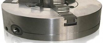
The spindle of a lathe must impart torque to the part being processed on the machine. To do this, a clamping device that best matches the workpiece is attached to the end of the spindle. There are a large variety of clamping devices, but usually this is a three-jaw chuck - it ensures reliability and accuracy of clamping, ease of installation and removal of most symmetrical parts.
The design of the spindle end of a lathe must satisfy the following requirements:
- Ensure secure fastening of the lathe chuck
- Ensure accurate alignment of the chuck relative to the spindle axis
- Ensure installation and removal of the cartridge for replacement in a minimum amount of time
DIY lathe chuck
Even today, lathes play a huge role in the production of certain parts.
All components and all equipment on any machines change over time, as they are subject to wear. All these elements of equipment must be of high quality and durable, since the quality of the finished product depends entirely on the quality of the installed parts. So is the lathe chuck. It is without this element that the machine becomes useless. Below we will analyze everything related to this element of the lathe. Let's start by finding out what this part is.
Basic dimensions and designations
If we take the most common three-jaw chucks (GOST 2675-80), then the current standard provides for ten standard sizes determined by the overall diameter of the equipment: 80, 100, 125, 160, 200, 250, 315, 400, 500 and 630 mm (see Table 1)
Depending on the method of installation on the spindle, the equipment is divided into three types:
- With belt and fixation by means of an auxiliary flange (Type 1);
- With fixation through a flange at the end of the spindle under a rotary washer (Type 2);
- With fixation through a flange at the end of the spindle (Type 3).
There is a unified designation system for the main parameters of the cartridge, consisting of 8 numbers and a letter indicating the accuracy class of the equipment. Using the table in GOST 2675-80 based on product labeling, you can determine:
- Number of clamps;
- Product diameter;
- Basic dimensions;
- Type of fastening of equipment to the spindle;
- Execution of clamps;
- Accuracy class.
So, for example, Chuck 7100-0032-P GOST 2675-80 designates the second type, diameter 200 mm, mounting on a spindle with standard size 5, prefabricated jaws and increased accuracy class (P).
General concepts
The chuck is one of the main elements of turning equipment. It is due to this that the future workpiece is fastened (installed). It is attached to the headstock with the gearbox. The chuck mechanism consists of a cam device.
Purpose
It is this part of the machine that has the most important mission in any workpiece processing. Due to the cam mechanism, which is located inside the chuck itself, the workpiece is clamped and centered. This happens due to the simultaneous narrowing of the cams around the plane of the workpiece. After clamping the workpiece, the workpiece is clamped with a quill located on the tailstock. When these actions are completed, the machine starts and the part rotates, which can be processed.
Variety
Nowadays, lathe chucks are distinguished by the presence of fastening elements (jams). There are only three of these types:
Double cam
Such cartridges are capable of securing complex, asymmetrical and shaped parts. In such cartridges it is possible to secure surfaces that are not subject to treatment. They are used in small production, as well as in serial production.
Three cam
This type of equipment is the most common and is used in all work. Allows you to process round and hexagonal parts. This type of chuck uses three different jaws. Regardless of this, the workpiece is centered together with the clamping of all three cams.
Four cam
This type is used for processing rectangular workpieces. Here, for each cam, there is a separate mechanical unit, which makes all cams independent.
Types of jaw chucks
But the types of cartridges do not end with three types. They are also divided according to the mechanism for fixing the workpiece:
Collet
They consist of a sleeve with slots in which the petals are located (various modifications include from 3 to 6 petals). These petals act as cams.
Wedge
This type of equipment is used mainly on machines with numerical control. secured using 3 cams, which are located on a flat spindle.
Lever
These cartridges contain sliders, with the help of which the cams move by lever force. This type is used for small-scale production, as well as for processing a single workpiece.
Membrane view
In this case, a pneumatic drive is used, with the help of which the membrane is compressed. This type is used only for fine processing, to remove a thin layer of chips.
Drilling
These chucks are similar in principle to chucks for hand drills. When the nut is tightened with a special wrench, the cams are smoothly squeezed out. Due to this action, the part or tool is clamped.
Thermal cartridge
This type of device is very inconvenient to use. This is due to the fact that when attaching the workpiece, thermal heating of the chuck itself is performed, and the same actions are performed when removing the tool.
Hydraulic chuck
The principle of operation is similar to that of a thermal cartridge. The part is clamped by a liquid that compresses the cams under pressure. Due to the liquid contents in the cartridge, additional damping of vibrations that occur during operation is performed.
Design
Design of jaw lathe chuck
Let's look at the structural elements that make up the lathe chuck itself:
Used to carry out clamping actions.
Spring
Allows you to use the key to perform certain actions to clamp the part and vice versa.
Sleeve
Produces free passage of the key.
Stopper
Prevents the part from unscrewing while the machine is running.
Gear
Transmits rotational motion to the spiral disk.
Flange
The part on which the entire structure is fixed.
Spiral disc
Due to the rotational movement of the gear, this disk drives the cams.
Reverse cam
Used for clamping the workpiece from the inside.
Cam straight
Used for clamping the workpiece from the outside.
Frame
An element of a part on which the cam mechanism is located.
Overhead cams
For clamping long and short parts with large diameters.
Each of the parts of the entire mechanism performs a specific function and is not superfluous.
Assembly according to drawings
Drawing of a three-jaw chuck
The jaw chuck for turning equipment is assembled according to diagrams that can be downloaded from the Internet and printed on a printer. As a rule, factory cartridges cost a lot of money and therefore many have learned to make such parts homemade . Their design is simple, but quite understandable. Before you begin assembling this fixture, you must fully understand the entire mechanism of the chuck and cam mechanism. If it is not possible to make such elements yourself, then they can be ordered from any turner. It won't cost much.
Assembly begins with a flange on which all the necessary holes for fastenings are located. Following this, all the parts of the mechanism are gradually installed, which are completed by covering with the case and bolting the entire cartridge
Double jaw chucks
2-jaw lathe chucks are used for fastening complex asymmetrical and shaped workpieces (non-cylindrical), i.e. in such cases, when installation in a three-cam requires much more time or is not possible at all. Self-centering 2-jaw devices are capable of securing untreated surfaces in replaceable jaws.
The body is made of steel 45, cast iron, the cams are made of case-hardened steel, for example, 20X, the lead screw is made of alloy steel. Moving parts are heat treated.
Double jaw chucks are produced in two types:
- manual - the part is clamped by turning the special a key inserted into the socket, as a result of which the cams move and center the part relative to the spindle axis;
- mechanized - with a pneumatic drive - the unit has a pneumatic cylinder with a piston that moves the sliders, which release and clamp the workpieces.
The diameters of manufactured devices are standardized: 150, 200, 250, 300, 375 mm. 2-jaw turning units with a pneumatic drive are manufactured with diameters of 160, 250, 320, 400 mm with a cam stroke of 5 - 10 mm.
The main disadvantage is the displacement of the center of the workpiece due to the misalignment of the cams in the guides due to the gap. Therefore, it is extremely important to minimize the clearance between the cams and the guides.
How to install a chuck on a lathe?
Installing a chuck on a lathe can be done using several methods, it all depends on the specific type of this element that you will be dealing with.
There are two types of chuck mounting on a lathe spindle:
Threaded fastening is used on small machines with light types of chucks, flanged on medium and heavy machines.
If it is light, it is quite easy to install on the machine without outside help, then heavy ones (more than 20 kg) are installed with the help of auxiliary lifting mechanisms, or in tandem with a partner. Let's consider the procedure for installing a heavy flange-mounted chuck on a lathe.
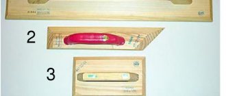
To install a heavy chuck, you need to prepare two mounting fixtures.
- mounting stand;
- guide
The mounting stand is made from a board approximately 50 mm thick. The width is equal to 1.5 times the width of the installed cartridge, the length of the stand L- corresponds to the width of the bed-B and the radius-D.
The blocks are attached to the bottom of the stand. Through vertical through holes, the stand is bolted to the movable rest of the machine support. The height of the stand is adjusted by the thickness of the bars.
Between the steady rest with the stand attached to it and the chuck still installed on the machine, the gap should be 1-3 mm.
The guide is a cylindrical shaft with a diameter of 25-40 mm, with a shank in the form of a Morse cone of at least number three. The length of the cylindrical part of the guide is equal to 1.5-2.0 times the width of the installed cartridge.
The ends of the spindles are threaded. GOST 16868 (Instead of OST 428)
Attaching the chuck to the threaded end of the spindle
GOST 16868 (Threaded spindle ends) offers two standard sizes of spindle ends:
Threaded spindle end GOST 16868
In reality, there are many models of machines produced before the early 60s , with threaded spindle ends from M33 to M150. The threaded end of the spindle was used on old model , for example, 1A62 (M90 x 6) and in small lathes - educational and desktop, for example, TV-7 (M45 x 4.5), etc.
TV-4 machine (d = M36 x 4), it is necessary to manufacture a non-standard intermediate flange using the mounting dimensions of the required chuck.
In order to secure a lathe chuck at the front end of the spindle, it is necessary to make or purchase an intermediate (adapter) flange , which is also called a faceplate .
On the spindle side, the intermediate flange must be screwed onto the spindle thread d and very accurately slide onto a cylindrical centering belt with a diameter of Ø d1 and a length of l mm.
On the side of the lathe chuck, the intermediate flange must have a centering belt - step D4 for precise installation and centering of the lathe chuck on the intermediate flange, and also have through holes for attaching the chuck. Obviously, for each standard size of lathe chuck there must be its own intermediate flange.
It is allowed to install 1 locking device against self-unscrewing on the intermediate flange of the design.
The disadvantage of threaded spindles is that when braking or reversing a high-speed machine, the chuck can jump off the spindle due to inertia. In addition, the lathe chucks mounted on these spindles with a sliding fit are not perfectly centered. Centering accuracy is affected by the clearance. With frequent screwing and unscrewing of cartridges, the gap increases due to wear of the mating surfaces. Under these conditions, even tight connections lose their original accuracy over time, and the need to repair the spindle head arises.
Medium and large lathes use flanged spindle ends with a centering short taper (7°7′30″). Tapered guides provide more accurate centering when installing chucks and faceplates.
Installation procedure
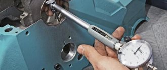
Before installing it, you should carefully check the condition of the surfaces of the spindle and chuck. Surfaces should not have nicks, scratches, burrs or contaminated areas.
Identified defects are eliminated point by point with a file or scraper. You should check the runout of the end and cone of the spindle landing base, which should not exceed three microns.
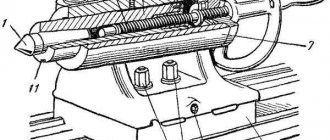
Place a metal rod or pipe with a diameter of about 20 mm into it. clasp it with your fists. With a partner, grasp the rod on both sides, or using lifting mechanisms, through the mounting loop, move the cartridge onto the mounting stand fixed to the machine support.
Install the guide in the tailstock. The chuck should be shifted by rolling towards the spindle axis.
Using a longitudinal feed, move it to the spindle flange so that the chuck studs do not reach the mounting holes of about 10 mm. The machine should be set to neutral speed to allow the spindle to rotate freely.
Move the tailstock with the quill completely retracted forward towards the chuck so that the guide extends over the entire width of the cam prisms and fix the tailstock.
Clamp the jaws of the chuck to transfer the weight to the guide. Align the key on the spindle flange with the mounting hole. Set the rotary washer to the position of the open holes. Using the quill, push the cartridge forward until it stops.
After making sure that all the stud nuts are out of the back of the spindle flange, turn the rotary washer to the locked position. Tighten the top nut with enough force to transfer the weight of the chuck onto the spindle. Open the cams and move the tailstock back. Compress the nuts according to the rule crosswise, evenly distributing the force between the studs.
After installation is completed, the chuck should be checked for axial and axial runout. If the standards are exceeded, it should be removed and all mating parts of this assembly should be carefully inspected.
Video: installation of a lightweight cartridge on a threaded fastener.
Intermediate flanges for self-centering cartridges GOST 3889-80
This standard applies to intermediate flanges intended for installation on the ends of spindles of metal-cutting machines with self-centering general purpose chucks.
Intermediate flanges (they are also called plan washers) are necessary for centering and fastening chucks with a centering belt (GOST 2675 type 1) on any of the 4 types of lathe spindle ends.
GOST 3889-80 (DIN 6350) Flanges must be manufactured in the following versions:
- Version 1 - installed on the threaded ends of spindles in accordance with GOST 16868;
- Version 2 - installed on the flanged ends of spindles in accordance with GOST 12593 under a rotary washer;
- Version 3 - installed on the flanged ends of spindles in accordance with GOST 12595 version 1;
- Version 4 - installed on the flanged ends of spindles in accordance with GOST 12595 version 3.
GOST 3889 Version 1. Intermediate flanges for threaded ends of spindles
GOST 3889 Intermediate flanges for threaded ends of spindles
DIY lathe chuck
Even today, lathes play a huge role in the production of certain parts. All components and all equipment on any machines change over time, as they are subject to wear.
All these elements of equipment must be of high quality and durable, since the quality of the finished product depends entirely on the quality of the installed parts. So is the lathe chuck. It is without this element that the machine becomes useless. Below we will analyze everything related to this element of the lathe. Let's start by finding out what this part is.
Types of faceplates
The simplicity of the faceplate design and wide range of use have given rise to a large number of ways to secure workpieces. However, the device is not completely universal. Different situations may require several different modifications.
Faceplate with T-slots
On the surface of such equipment there are T-shaped grooves, similar to those used on tables of milling machines. Special stops or fastening nuts are inserted into these grooves. The workpiece is pressed to the plane using screws. The design of the device allows you to fasten almost any product. The arrangement of grooves on the surface of the disk is usually orthogonal. Depending on the purpose, the number and frequency of grooves may vary.
Faceplate with through grooves
This type is distinguished by the presence of grooves milled through the part. The workpiece is secured by installing screw clamps. In some cases, the part is simply screwed on from the reverse side. Grooves are most often located along a radius. There are also modifications with ring-type through grooves.
In most cases, grooved faceplates are used for metal lathes. Other turning devices can be easily installed on their surface.
Faceplate with holes
The working surface of the disk of this device has a number of holes located according to the dimensions of the workpiece being fixed. The central hole is threaded, necessary for direct fastening to the spindle shaft. The presence of threads in the mounting holes allows for fastening with standard screws. In other situations, the clamp is performed similarly to the previous option. When using a similar faceplate for a wood lathe, the future part is secured through the holes with ordinary self-tapping screws.
General concepts
The chuck is one of the main elements of turning equipment. It is due to this that the future workpiece is fastened (installed). It is attached to the headstock with the gearbox. The chuck mechanism consists of a cam device.
Purpose
It is this part of the machine that has the most important mission in any workpiece processing. Due to the cam mechanism, which is located inside the chuck itself, the workpiece is clamped and centered. This happens due to the simultaneous narrowing of the cams around the plane of the workpiece. After clamping the workpiece, the workpiece is clamped with a quill located on the tailstock. When these actions are completed, the machine starts and the part rotates, which can be processed.
Variety
Nowadays, lathe chucks are distinguished by the presence of fastening elements (jams). There are only three of these types:
Double cam
Such cartridges are capable of securing complex, asymmetrical and shaped parts. In such cartridges it is possible to secure surfaces that are not subject to treatment. They are used in small production, as well as in serial production.
Three cam
This type of equipment is the most common and is used in all work. Allows you to process round and hexagonal parts. This type of chuck uses three different jaws. Regardless of this, the workpiece is centered together with the clamping of all three cams.
Four cam
This type is used for processing rectangular workpieces. Here, for each cam, there is a separate mechanical unit, which makes all cams independent.
Types of jaw chucks
But the types of cartridges do not end with three types. They are also divided according to the mechanism for fixing the workpiece:
Collet
They consist of a sleeve with slots in which the petals are located (various modifications include from 3 to 6 petals). These petals act as cams.
Wedge
This type of equipment is used mainly on machines with numerical control. secured using 3 cams, which are located on a flat spindle.
Lever
These cartridges contain sliders, with the help of which the cams move by lever force. This type is used for small-scale production, as well as for processing a single workpiece.
Membrane view
In this case, a pneumatic drive is used, with the help of which the membrane is compressed. This type is used only for fine processing, to remove a thin layer of chips.
Drilling
These chucks are similar in principle to chucks for hand drills. When the nut is tightened with a special wrench, the cams are smoothly squeezed out. Due to this action, the part or tool is clamped.
Thermal cartridge
This type of device is very inconvenient to use. This is due to the fact that when attaching the workpiece, thermal heating of the chuck itself is performed, and the same actions are performed when removing the tool.
Hydraulic chuck
The principle of operation is similar to that of a thermal cartridge. The part is clamped by a liquid that compresses the cams under pressure. Due to the liquid contents in the cartridge, additional damping of vibrations that occur during operation is performed.
Design
Design of jaw lathe chuck
Let's look at the structural elements that make up the lathe chuck itself:
Used to carry out clamping actions.
Spring
Allows you to use the key to perform certain actions to clamp the part and vice versa.
Sleeve
Produces free passage of the key.
Stopper
Prevents the part from unscrewing while the machine is running.
Gear
Transmits rotational motion to the spiral disk.
Flange
The part on which the entire structure is fixed.
Spiral disc
Due to the rotational movement of the gear, this disk drives the cams.
Reverse cam
Used for clamping the workpiece from the inside.
Cam straight
Used for clamping the workpiece from the outside.
Frame
An element of a part on which the cam mechanism is located.
Overhead cams
For clamping long and short parts with large diameters.
Each of the parts of the entire mechanism performs a specific function and is not superfluous.
Assembly according to drawings
Drawing of a three-jaw chuck
The jaw chuck for turning equipment is assembled according to diagrams that can be downloaded from the Internet and printed on a printer. As a rule, factory cartridges cost a lot of money and therefore many have learned to make such parts homemade . Their design is simple, but quite understandable. Before you begin assembling this fixture, you must fully understand the entire mechanism of the chuck and cam mechanism. If it is not possible to make such elements yourself, then they can be ordered from any turner. It won't cost much.
Assembly begins with a flange on which all the necessary holes for fastenings are located. Following this, all the parts of the mechanism are gradually installed, which are completed by covering with the case and bolting the entire cartridge
Installation
Installing the jaw chuck
Installation is carried out as follows and in strict sequence:
Installation of the mandrel
First of all, this part is installed to ensure complete fitting of the cartridge.
Installing the chuck itself on the spindle
Using a frame, it is put on the spindle and secured with bolts.
Consolidation
The chuck is secured to the spindle with bolts. In this case, a simple open-end wrench will be a good helper.
Securing the workpiece
After installing the chuck, a part, workpiece or tool is fixed into it.
Three jaw chucks
The most common chucks are three-jaw chucks. They are installed on all turning equipment: in home workshops, garages, repair shops, small- and large-scale production.
The most common are 3 types of self-centering chucks:
- spiral:
- rack and pinion;
- eccentric with worm gear.
Three-jaw chucks are equipped with a traction (clamping elements are connected to a hydraulic or pneumatic drive) or a built-in drive. Up to thirty percent of auxiliary time is spent on clamping the workpiece during operation, so the devices are mechanized and reduce the time for installing the product. The most widely used in large-scale and mass production are powered jaw chucks with pneumatic drive. The hydraulic drive is rarely used and is used in situations where it is necessary to maintain small dimensions of the structure. The main advantage of mechanized units is their speed and constant clamping force on the jaws.
Detailed video on clamping turning units
Spiral cartridges
3-jaw scroll chucks have been around for over 100 years and, due to their simple design and reliability, are still used in new equipment today. They provide a large range of cam travel and have high efficiency; it is possible to clamp eccentric and non-round workpieces. The disadvantages are rapid loss of accuracy and accelerated wear. The loss of initial accuracy occurs as a result of technological features: the volute is only improving and has low hardness, therefore, it quickly wears out - rapid wear of the centering mechanism occurs. Accelerated wear occurs due to chips and dirt getting into the wedge-shaped gaps between the teeth of the cams.
Used in single and small-scale production. Equipped with direct and reverse cams.
Rack chucks
3-jaw rack chucks get their name because of the principle of operation: a gear rim moves the racks, which simultaneously moves the jaws. More durable than spiral ones, because It is possible to harden and grind the teeth. The body is made of cast or forged steel, the remaining moving parts are alloyed, followed by hardening. They are universal and are used in single or small-scale production.
- stronger clamp;
- greater accuracy;
- Efficiency is lower than that of spiral ones;
- Possibility of clamping from only one position;
- complex design.
Eccentric chucks
3-jaw eccentric chucks are used in large-scale production. All parts of the unit are made of wear-resistant steels, and then undergo hardening and grinding. They have high precision and clamping force. They can be re-adjusted to clamp another part relatively simply - by rearranging the mounted cams.
Varieties
To bore the jaws of a lathe chuck, it is necessary to choose the optimal method for a particular type. Several types of cams are produced, each of which has design features.
Direct
This type of cam is designed to clamp a workpiece with a shaft on the outside and for a workpiece with a hole on the inside. The cams are directly located on top and grip the part.
Reverse
Necessary for clamping the workpiece from the outside. Used for processing hollow blanks so that there is something to cling to.
Invoices
This is a composite version of the cartridge, which is made of non-ferrous metal or stainless steel. Used when working with large-scale projects. This variation is used when working with workpieces of large diameter, and it does not matter whether they are long or short.
Prefabricated
A metal cam in this type is mounted on a steel rail. Alloy steel is used, and the cam teeth are ground, hardened and carburized.
Four jaw chucks
4-jaw chucks are used for clamping non-round and asymmetrical workpieces. The jaws of the four-jaw chuck are independently adjustable and to machine the surface of the part, it must be installed so that its axis coincides with the axis of the spindle. Self-centering ones are not common. The devices are universal and are used in single and small-scale production in repair and tool shops.
Each cam is moved radially separately by the rotation of the screws.
To determine the possibility of processing in a 4-jaw chuck, it is necessary to calculate the ratio of the length of the workpiece and its diameter. If the result obtained is more than 4 units, then there is no possibility of processing.
On lathes they are mounted through an intermediate flange or directly on the flanged ends of the spindle.
How to squish it correctly?
To properly bore the cartridge, you must follow the sequence of actions. Professional boring is carried out in several stages, each of which must be performed with high quality and in accordance with all technical requirements.
Dismantling
First of all, it is necessary to dismantle the cartridge. Otherwise, it will not be possible to get rid of the workpiece runout and accurately align all the necessary axes. If the chuck is not clamped, but is in a free state on the machine, the defects will remain. After dismantling, it is necessary to remove the cams and clean them. Then you need to check the runout.
Sandpaper treatment
If there is a slight degree of wear and scuffing, it is enough to treat the part first with coarse-grained and then fine-grained sandpaper. In order not to distort the cam profile when sanding, it is necessary that the sandpaper covers approximately half of the cam profile and at the same time have a slight tension. If the cam wear is significant, full boring is necessary.
How to sharpen?
To groove the cams, a certain order must be followed:
- Install them by aligning them with the hole in the lathe chuck.
- Clamp the ring so that it can move freely.
- You will need two cutters: one for boring grooves, and the second for developing planes.
- Starting from low speeds, you should find the optimal rotation mode.
- The cutter for disassembling the planes must be installed so that contact occurs along the entire plane of the fists.
This way, conical boring is carried out and the workpiece can be fastened securely and safely.
Grinding
This is the final stage of boring, which is carried out only if there is a real need. At the same stage, a test is carried out with a metal shaft. The shaft is fixed in the chuck of the lathe and with its help it is possible to determine whether there is any runout. If there is runout, additional grinding is required.
Purpose and main parameters
A lathe chuck is one of the main elements of technical equipment and is necessary for reliable fastening of workpieces of various sizes and shapes to the spindle. High clamping accuracy ensures centering and perpendicularity of the surface of the processing axis. The chuck is necessary for almost all turning operations; it is included in the mandatory set of equipment for metalworking manual, semi-automatic and automatic machines.
This type of clamp is installed on the headstock of the machine. The transmission of rotation is carried out from the electric motor through the gearbox and transfer case. To ensure the production of parts, several lathe chucks are needed, which are selected taking into account the main operational and technical parameters:
- The design option and the number of cams (clamping elements) determine the possibility of fixing a particular type of workpiece, the location of the cams, and the possibility of installing several workpieces.
- Working diameter of the cartridge. This is the outer size, the diameter of the connecting belt, as well as the location and parameters of the mounting holes.
- Workpiece parameters. It is necessary to take into account the largest and smallest diameters, take into account the method of fastening - external or internal through reverse cams. It is also necessary to take into account the permissible mass of the part.
- The diameter of the hole in the cartridge body. Necessary when processing long rods.
- Maximum value of rotation speed.
Selecting a transfer method
In most homemade wood lathes, the working drive is provided by the two most popular methods - direct transmission or through belts. Both schemes are excellent for small-sized lathes with primitive devices for clamping a wooden workpiece in the form of a trident and a cone.
Direct transmission
This is a simple and effective way to drive a turning shaft. The actual working shaft here is the rotor shaft of the electric motor. The engine itself is attached to the frame or raised above the support. A clamping device is installed on the axle - a lathe chuck, a faceplate or a regular trident. This is, in principle, the whole scheme of direct drive of a lathe. The advantage of this scheme is that there is no need to look for a special turning shaft, grind out supports for it and center it. In the motor housing, the shaft is already mounted on bearings, and the engine itself has standard mounting units. The disadvantage of this scheme is that it is necessary to protect the windings from dust and shavings that will form during wood processing, and also, if you clamp the workpiece too tightly, there is a risk of the motor jamming and failure.
In addition, direct transmission does not allow adjustment of the speed. If the engine produces 1425 rpm, then the workpiece will also rotate, alas, this is clearly not enough for turning hardwood.
Belting
The design of the headstock using a belt drive significantly expands the capabilities of the lathe. Even if a pulley of the same diameter is used, this makes it possible to increase the shaft rotation speed and protect the electric motor from heavy loads; in this case, it is definitely not in danger of jamming.
If a multi-lane pulley is mounted on the working shaft, and the engine is mounted on a movable slide, then it becomes possible to regulate the speed of rotation of the shaft by moving the belt from a smaller diameter to a larger one. This is the best option; it makes it possible to process wood of a wide variety of species.
Manufacturing Features
Homemade wood lathes are made quite easily and simply if you know in principle what a lathe is and what it consists of. A small unit with dimensions of about 80x40 centimeters in length and width with a height of 35 centimeters does not take up much space, but allows you to process workpieces with a diameter of up to 25 centimeters and a length of 20-40 centimeters.
A lathe provides unlimited possibilities in the manufacture of dishes, furniture, and decorative elements.
Thanks to it, you can make any product in the form of bodies of rotation for your own use or during construction and other work.
What other GOSTs are associated with lathe chucks?
For various turning parts for metalworking machines, their own standards have been developed that fix all the necessary parameters. Main GOSTs:
- GOST 24351-80 For self-centering three- and two-jaw wedge and lever-wedge elements.
- Standard 3890-82 For four-jaw parts with independent movement of the jaws" indicating the main and connecting dimensions.
- 14903-69 For self-centering two-jaw elements.
- Gosstandart 2848-75 Tool cones. Tolerances. Methods and means of control.
- Gosstandart 12595 – 2003 – metal-cutting machines.
- State Standard 3889 – Flanges for self-centering chucks.
- Standard 12593-72 – spindle flange dimensions
All this technical documentation allows us to summarize and classify the varieties of these basic elements of turning equipment.
Three-jaw options with a diameter of 250 mm are most often used in lathes, both at the industrial and domestic levels. Therefore, the standards for their production in all respects must be strictly observed.
The document regulating self-centering spiral rack elements contains detailed dimensions, as well as separate diagrams and drawings of this part, from which it is possible to determine compliance with the declared data. At the slightest violation of the parameters specified in GOST, the quality of the working process of the lathe is significantly reduced.
Tips for use
Proper use of a lathe involves the following.
- Regular cleaning of equipment and regular chip removal will help minimize downtime, breakdowns and waste in turning operations. If maintenance is not carried out systematically, equipment breakdowns may increase dramatically, durability may decrease, and production costs may increase.
- To avoid equipment failure, you should regularly check the condition of the cutting edges and backs of working tools, sharpen or replace dull tools in a timely manner.
- All necessary components such as oil, coolant, tools, lathe accessories and fasteners must be of the correct quality and grade.
- Replacement of faulty parts and tools, elimination of simple faults.