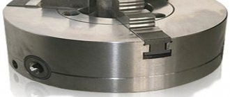
A lathe chuck is the main element of lathe equipment, a clamping device that ensures the fixation of workpieces on the spindle. The use of chucks allows processing at high rotation speeds, ensures installation accuracy and the required clamping force. Any lathe chuck has several cams in its design, which are special clamps for holding and centering the workpiece being processed. There can be 2, 3, 4 or 6 of them depending on the design and size of the cartridge. The cams are made of high-strength alloy steel and are designed for centering and fixing the workpiece in the working area.
Cams come in the following types:
- straight;
- reverse;
- soft or “raw cams”;
- prefabricated
File manufacturing technology
In Russia, two groups of tool steels are used for the production of files: unalloyed improved steels with a carbon content of 1 to 1.3% (YUA - U13A) or alloyed chromium steels ШХ15 or 13Х.
Similar steels are used by file manufacturers abroad. Carbon content of one percent and above allows the notch to be hardened to high hardness. The technology for producing files may differ significantly in detail from one production to another, but it always contains the following stages:
- Shaping processing;
- Formation of notches on working surfaces;
- Heat treatment.
The last two operations are especially important. The effectiveness of the file depends on how well the notch is made. When using worn-out equipment and tools, you can get a file that looks “just like a real one,” but in which, say, no more than 30% of the cuts work.
The service life of the file depends on the quality of the heat treatment.
The distribution of hardness and viscosity along the depth of the file body is very important here. Hardness should be maximum on the surface and gradually decrease in depth, viscosity - vice versa. Low hardness leads to rapid dulling of the notch teeth, and low viscosity (i.e.
high fragility) – to their rapid destruction during operation
Low hardness leads to rapid dulling of the notch teeth, and low viscosity (i.e., high fragility) leads to their rapid destruction during operation.
Most manufacturers regulate the nominal surface hardness of files depending on their purpose as follows:
- Bench files: 64 to 66 HRc.
- Sharpening files: 65 to 67 HRc.
- Rasps: 53 to 56 HRc.
The quality of a file can only be fully checked during its operation. The quality of files (both efficiency and service life) is especially important for industries in which manual filing is part of the technological process. There are still many like this. This is the production of some types of hand tools, forestry, where chain saws are used, which require periodic sharpening of cutting chains, and many others. When using files in production, it is necessary to constantly monitor their efficiency and service life, since experience shows that almost any file manufacturer can have defective files.
The length of a file always refers to the length of its working part (the entire part, not just the cut part), without the shank. The exception is needle files. For them, the total length is always indicated, including the shank (if any).
In metric countries, the following range of sizes (in mm) are used: 100, 125,150, 200, 250, 300, 350 and 400.
Most manufacturers use only part of the denominations from this series.
General concepts about lathe chucks
Lathe chucks are selected depending on the technical characteristics of the device and the spindle, in particular. They represent the main components of the equipment. The mechanism is a cam effect. Dimensions are selected depending on the parameters of the unique workpiece.
The cams ensure reliable fixation of the mechanism. Due to the action of mechanical force, which determines the tightness of the fastening, installation and fastening occurs. The workpiece is fixed using a chuck.
A low-quality cartridge will not hold as tightly as possible; as a result of strong mechanical movement, it can fly off, and the workpiece with it. The chuck ensures smooth movement of the fastener, while the workpiece will not move relative to the center. In the simplest sense of the word, a chuck is a mechanism that is responsible for rotating the workpiece, making its processing efficient and smooth.
Cartridge accuracy classes
The accuracy of the device is determined in GOST 1654 86. There are four stages in total.
Class H
Normal indicators, averaged.
Class P
Higher class, used for making hard production parts.
Class B
High accuracy - used for processing small variations.
Class A
Particularly high accuracy. Scope of application: small and hard workpieces.
Specifications.
The chuck body is made of high quality special cast iron
Table 1
| Name of parameters | Values |
| Outer diameter D, mm | 250 |
| Diameter of connecting belt D2, mm | 200H7 |
| Diameter of hole in housing D1, mm | 76 |
| Diameter of mounting holes, mm, D3 | 224 |
| Outer diameter of the product clamped in straight jaws, largest mm | 120 |
| Outer diameter of the product clamped in the return jaws, largest mm | 266 |
| Maximum permissible rotation speed, min ' | 2000 |
| Flange side height | 5 |
| Chuck height without jaws | 85 |
| Height of chuck assembly | 119 |
| Cartridge weight, kg | 29 |
| Fasteners | 6 M12 bolts |
Using a lathe chuck, using straight and reverse jaws, you can clamp workpieces in the following range of sizes
The straight cam is designed to secure the workpiece to the outer surface of the shaft or to the inner surface of the hole in the workpiece. The reverse cam is designed to secure the workpiece to the outer surface.
Accuracy characteristics of lathe chuck
Fig.2.1 - Lathe chuck at idle speed
the cartridge provides the following accuracy characteristics: Radial runout a – 0.045 mm;
End runout c – 0.025mm.
By securing the workpiece in the chuck, the following characteristics can be achieved:
Scheme I:
range of fixed workpieces from 5 to 118mm;
Radial runout a at a length of 80 mm is 0.040 mm.
Scheme II:
range of fixed workpieces from 77 to 188 mm and from 160 to 250 mm;
Radial runout a – 0.045mm;
End runout c – 0.025mm.
Scheme III:
Prices and manufacturers
Almost all turning jaws that can be bought in Russia are produced at two factories:
- BelTAPAZ is a Belarusian enterprise of cartridges and spare parts for them;
- Bison-Bial is a Polish plant whose main specialization is the production of cutting equipment.
Approximate prices are shown in the table.
| product name | Price, rubles |
| Reverse jaws for 80 mm chuck | 2600 |
| Straight jaws for 80 mm chuck | 2600 |
| Reverse jaws for 100 mm chuck | 2800 |
| Straight jaws for 100 mm chuck | 2800 |
| Prefabricated reverse jaws (overhead) for 250 mm chuck | 5500 |
| Straight jaws (overhead) for a 250 mm chuck | 5500 |
| Reverse jaws for 315 mm chuck | 10000 |
| Straight jaws for 400 mm chuck | 18400 |
Source of the article: https://orgstanki.ru/obzor-kulachkov-na-tokarnye-patrony.html
Jaws for lathe chucks
Machine tooling and accessories / Jaws for lathe chucks
The Uralremdetal enterprise supplies jaws for lathe chucks in accordance with GOST produced by BelTAPAZ (Belarus) and Bison Bial (Poland).
Clamping (straight) jaws for lathe chucks
Scheme
Jaws for lathe chucks
Standard sizes of jaws for lathe chucks
| Marking | Ø | E | F | G | H | J | K | L | M | S |
| Ch7100-0001.004 | 80 | 32 | 11 | 31.5 | 6.5 | 6 | 11 | 11 | 7 | 6 |
| Ch7100-0002.004 | 100 | 42 | 15 | 36 | 6.7 | 6 | 14 | 14 | 7 | 6 |
| Ch7100-0003.004 | 125 | 51 | 20 | 38.5 | 8 | 8 | 16 | 19 | 7.5 | 7 |
| 7Ch100-0005.004 | 160 | 70 | 20 | 52 | 8 | 8 | 20 | 20 | 12 | 7 |
| S7100-0033.00 | 200 | 85 | 28 | 60 | 8.5 | 10 | 29 | 29 | 14 | 8 |
| S7100-0035.004 | 250 | 105 | 28 | 63 | 11.5 | 12 | 32 | 32 | 15 | 9 |
| С7100-0041.004 | 315 | 125 | 36 | 91 | 13 | 12 | 40 | 40 | 24 | 10 |
| 7100-0045.004 | 400 | 145 | 36 | 92 | 15 | 12 | 40 | 50 | 22 | 10 |
Note: jaws for lathe chuck Ø 250 until 1987, size H = 9.5 mm. , S =10 (С7100-0035.015/03), in 1987-1992 size H =11.5 mm, S=10 (С7100-0035.015/01). After 1992 H = 11.5 mm, S = 9 mm. (C7100-0035.015). The jaws (C7100-0035.015/02) are suitable for Polish chucks.
Expanding (reverse) jaws for lathe chucks
Jaw sizes for lathe chucks
| Marking | Ø | E | F | G | H | J | L | K | M | S |
| Ch7100-0001.006 | 80 | 32 | 11 | 31.5 | 6.5 | 6 | 11 | 11 | 7 | 6 |
| Ch7100-0002.006 | 100 | 42 | 15 | 36 | 6.7 | 6 | 14 | 14 | 7 | 6 |
| Ch7100-0003.006 | 125 | 51 | 20 | 38.5 | 8 | 8 | 16 | 19 | 7.5 | 7 |
| Ch7100-0005.006 | 160 | 70 | 20 | 52 | 8 | 8 | 20 | 20 | 12 | 7 |
| S7100-0033.008 | 200 | 85 | 28 | 60 | 8.5 | 10 | 29 | 29 | 14 | 8 |
| С7100-0035.015 | 250 | 105 | 28 | 63 | 11.5 | 12 | 32 | 32 | 15 | 9 |
| S7100-0041.009 | 315 | 125 | 36 | 91 | 13 | 12 | 40 | 40 | 24 | 10 |
| 7100-0045.009 | 400 | 145 | 36 | 92 | 15 | 12 | 40 | 50 | 22 | 10 |
| С7100-0035.015/01 | 250 | 105 | 28 | 63 | 11.5 | 12 | 32 | 32 | 15 | 10 |
| S7100-0035.015/02 | 250 | 105 | 28 | 63 | 11.0 | 12 | 32 | 32 | 15 | 10 |
| S7100-0035.015/03 | 250 | 105 | 28 | 63 | 9.5 | 12 | 32 | 32 | 15 | 10 |
Note: jaws for lathe chucks Ø 250 until 1987, size H = 9.5 mm. , S =10 (С7100-0035.015/03), in 1987-1992 size H =11.5 mm, S=10 (С7100-0035.015/01) after 1992 H = 11.5 mm, S = 9 mm. (C7100-0035.015). The jaws (C7100-0035.015/02) are suitable for Polish chucks.
Place an order or ask a question
Questions and answers
We need three-jaw self-centering chucks with cone mounting F250 and F315. Which manufacturers' products do you recommend?
Good cartridges are produced by a plant in Grodno (Belarus). The chuck jaws fit tightly, but burrs are visible during disassembly. Polish lathe chucks “Bison” and “Porebra” have the best quality, but their price is noticeably higher. If you do not want to modify the equipment, we recommend choosing products from Polish manufacturers. If you are ready to work with a file, Belarusian cams will do.
For machines 16k20 and mk60 with chucks with a diameter of 250 mm, direct and reverse jaws are needed. What numbers are suitable?
According to the standard sizes of jaws for lathe chucks, jaws marked C7100-0035.015/02 are suitable. If lathe chucks of the same diameter were produced before 1987, you will need jaws marked C7100-0035.015/03. For understanding, we provide a table.
Jaw sizes for lathe chucks
What shapes do needle files have?
Diamond needle files are available in 12 types.
- Tools with three edges. They have a sharp or blunt end. This indicator determines the area of use of the device.
- Devices made in the shape of a rhombus. They make it possible to play with notches at a certain angle.
- Wedge-shaped devices are used when working with castes and valves (jewelry elements), as well as with angles with small values. Wedge-shaped devices have both a sharp and a rounded edge, but the nose of the device is sharp.
- The flat diamond needle file has versatility of use. The area of use depends on the size of the device.
- Grooved devices are similar to flat ones, but the edges on the sides are rounded. This makes it possible to treat hard-to-reach areas.
- Square devices are designed to work with grooves of a similar shape.
- With a semicircular shape. With their help it is possible to work with reliefs.
- Needle files with different convexities process the inner part of the ring.
- Oval fixtures are designed for holes.
- The round diamond needle file is able to work with rounded products. In addition, with their help, the required relief is created.
- The needle shape is fundamentally different from all other types. Firstly, it should be noted that these devices are miniature. The length of the working surface is 35-55 mm. Secondly, their tail is square.
- Another special type is the needle file. It should be discussed separately.
Devices with a blunt nose have the same cross-sectional size along their entire length. In pointed models, the cross-section of the rod decreases towards the edge of the device.
The notching itself is also performed in accordance with the standards. The main working parts of the tool have a double notch: main and auxiliary. Tools with a round or oval shape can have a single or spiral single cut.
Rules for working with a file
In order to perform the tasks for which the device was created, it is necessary to apply its grooved zone with little force to the area that is to be filed. Then, without loosening the pressure, set it in motion. The teeth of the tool's notch will begin to remove the top from the workpiece. This action is defined by the technical term “layer-by-layer cutting of material from the surface.” The quality of the cut is the result of the correct choice of the notch number, and productivity is determined by the pressing force and the frequency of tool movements along the workpiece. The final processing of the part is carried out with a file or velvet file. Wood processing is done with a rasp.
A file is a hand tool. To start working with it, you need to perform the following operations:
- Check the serviceability of the tool. The handle should fit tightly, without play.
- Familiarize yourself with the safety rules and strictly follow them.
- Firmly secure the workpiece in appropriate devices, for example, in a vice or press it to the workbench with a clamp. It is desirable that the surface to be processed is horizontal. The part should protrude above the surface of the vise jaws by approximately 5 - 8 mm.
- If the worker is right-handed, then he takes the file by the handle in his right hand, places the tool with the working part on the area of the part intended for processing, gently presses it to the part with his left hand and begins horizontal forward-return movements back and forth. When moving forward, you need to press on the handle and toe. The direction of movement is approximately 45 degrees to the front of the workpiece. For each forward movement, the file removes a certain amount of material from it. Using a brush (cord) made of hard wire, it is necessary to remove chips from the gear field. To prevent clogging of the notch with non-ferrous metal filings, experts advise rubbing the tool with chalk before starting work.
- If the plane of the part is processed with a flat file, then after each working pass the tool should be moved to the side perpendicular to the working stroke. This way the entire treatment area will be covered.
- It is necessary to ensure that the tool moves without distortion, otherwise scratches and grooves will appear on the part.
- If the task is to process a narrow strip between two walls, then care must be taken not to damage the restricted area.
- When reaming a round or shaped hole, you must also monitor the change in its shape as a result of the work of a round or square file.
Experienced craftsmen often upgrade the tool, customizing it to their taste and specific tasks. They change the length, sharpen the end, make a more comfortable handle.
A file is used to refine a part that has been turned on a lathe. Using a hand tool, the grooves from the cutter are removed, grooves are formed, and chamfers are removed.
Device and principle of operation.
3.1. The design of a spiral rack lathe chuck is shown in Fig. 3.
Fig. 3 - Design of a spiral rack lathe chuck.
Cams 1, 2 and 3 of the cartridge move simultaneously using disk 4. On one side of this disk there are grooves (shaped like an Archimedean spiral) in which the lower projections of the cams are located, and on the other there is a cut bevel gear mated to three bevel gears 5. When you turn one of the wheels 5 with a key, disk 4 (thanks to gearing) also turns and, by means of a spiral, simultaneously and evenly moves all three cams along the grooves of the cartridge body 6. Depending on the direction of rotation of the disk, the cams move closer to the center of the chuck or move away from it, clamping or releasing the part. The cams are made in three stages and are hardened to increase wear resistance.
Boring and grinding lathe chuck jaws: procedure
Wear of the rubbing parts of a lathe chuck is a typical problem for a turner. It leads to workpiece beating and poor processing quality. In this case, it is not necessary to replace the part with a new one. Sometimes it is enough to simply bore the jaws of the lathe chuck.
Boring is also required to give the required dimensions to non-hardened (raw) jaws, which are usually used to clamp workpieces with non-standard geometry.
Due to high speeds and loads, the lathe chuck periodically wears out and accuracy is lost. The machine operates at high speeds. As a result, there is a loss of cylindrical girth of the workpiece due to uneven wear of the clamping surfaces of the cams. This leads to beating of the processed blank and defects due to the fact that the part does not meet the declared dimensions and quality requirements. And in the long term, it can lead to breakdown of the main components of the machine.
The main purpose of boring is to align the axis of the working surfaces of the chuck jaws with the axis of rotation of the spindle.
Types of turning jaws
Lathe chuck jaws come in several types.
Direct
used for clamping a workpiece from the outside with a shaft or on the inside for a workpiece with a hole.
Reverse
necessary for clamping the workpiece from the outside. They are designed for turning hollow parts.
Invoices
are used when processing something large-scale: when the length of the workpiece is too long or the diameter size is large (and in this case it does not matter how long the workpiece itself is). Prefabricated
Prefabricated
consist of a rail on which an overhead cam is attached.
Regardless of the type of cams, recommendations for boring them are universal.
How to bore the jaws correctly?
Professional boring is carried out in several stages. If you perform each of them efficiently, following all technical recommendations, then the equipment will serve you for a long time.
To bore the jaws, follow the following procedure:
1. Dismantling the lathe chuck.
2. Processing with sandpaper.
3. Boring of the jaws.
4. Grinding the cams (if necessary).
We'll tell you more about it below.
Removing the lathe chuck
The first step is to dismantle the lathe chuck. Otherwise, you simply will not be able to eliminate the runout of the part and correctly align all the necessary axes. If the chuck is not clamped on the machine, the malfunction will persist.
After dismantling, remove the cams and clean them. The next step is to check the runout.
Sandpaper treatment
If the wear is slight, it is enough to treat the cartridge part first with coarse-grained and then with fine-grained sandpaper. Sometimes this method helps restore the cylindrical girth.
However, with a large degree of wear on the cams, you will have to resort to full boring.
Boring
1. First, secure the jaws so that the diameter between them matches the size of the lathe chuck hole.
2. Clamp the ring with your fists so that it can move freely.
3. For boring, you will need two cutters: one for boring grooves (so that chips and production waste can be freely removed from the hole), and the second for developing planes.
4. Start with low speeds and gradually increase the speed, set the optimal rotation mode.
5. We start boring with the first cutter, choosing the optimal groove depth so that the surface of the cams is within the permissible area.
6. Then we use a cutter to disassemble the planes. It must be secured so that contact occurs along the entire working plane of the fists.
7. At the end, we make a conical boring of the cams, so that in the future the workpiece being processed can be firmly attached to them, making the grip reliable and safe.
Grinding
The final stage of boring the cams is grinding, which is carried out only if it is really necessary. How can I check this? Clamp the metal shaft with the jaws and start the machine. If there is runout, you will have to grind it.
To do this, you need to process the inside, holding the ring with them so that the cams do not unwind spontaneously.
The easiest method is grinding using a cutter with a special stone.
If you follow the above procedure completely, the cams will serve you for a long time.
You can choose high-quality clamping jaws SMW-Autoblok (Germany) in our catalog.
How we are working?
After you submit your application, our manager will contact you at the specified time. With him you will agree on all the details of the upcoming work. You will also need to provide a drawing drawn up in compliance with all engineering graphics standards. If you do not have specialists who could develop it, our employees will take on this task. As an analogue, you can provide:
- technical task,
- photo of the product,
- sample part.
Based on this, a drawing will be developed, which will then be sent to production.
The method of manufacturing the jaws is not technically complex, but requires sufficient precision to ensure that the product fits the chuck.
Once the required batch of parts is ready, we send it to the client using our own delivery service.
Along with the finished cams, you will receive a full set of accompanying documents.
Overview of species
Different spray-coated tools can vary significantly in performance, despite the fact that they are all used for metal work. Some are needed for roughing, others for finishing sanding or filing small parts. According to GOST 1513-67, needle files must be marked indicating the main parameters. Tools can be divided into groups according to a number of characteristics.
By shape
The type of profile indicates for what purpose a particular file is suitable. Acceptable forms are established by the state standard. There are quite a lot of them, which allows you to choose tools for different stages of work.
Flat, with a blunt nose:
- have a rectangular shape;
- have 4 edges, 2 of which are wide and the rest are narrow;
- Suitable for both processing flat surfaces and cutting grooves and other hard-to-reach places.
There are also flat needle files with a sharp nose. They are distinguished by a different shape of the tip of the working part, otherwise they have the same features as obtuse-angled products.
Rhombic:
- upper corners – blunt;
- there are diamond-shaped edges;
- scope of application – processing of parts with different angles.
Square products are needed for filing rectangular grooves. All edges of the tool are working.
Triangular files come in two types:
- pointed - suitable for processing external grooves in small parts, all edges are involved in the work;
- obtuse-angled - they can have either one working side or all three; the latter option is more popular.
Round instruments usually have a sharp tip. They are suitable for turning relief elements. Similar in shape are oval models; they can be used to process round parts.
To size
Product parameters are usually indicated in the labeling. It can contain three numbers, for example, one of the popular sizes 140x70x3, where 140 mm is the length of the product, and 70x3 mm is its cross-section. Files with parameters 140x50x3 are also in demand. For some shapes, the section is indicated by one number, for example, a 4 mm round needle file.
The length of the products may vary, but the most commonly used tools are 80 mm, 120 mm, 160 mm. If necessary, you can purchase a file from 100 mm to 450 mm for work.
By grain level
Depending on the purpose, the coating of the file may vary
It is worth paying attention to the density of the grains. If there are few of them, then after processing the product will be rough, but with a fine-grained file you can make the surface smooth. For convenience, color markings are applied to the handle of the instruments:
For convenience, color markings are applied to the handle of the instruments:
- red – grain density ranges from 160 to 80 units;
- blue – grain size ranging from 80 to 55;
- if there are no markings, then the coating may have 50-28 grains per 1 cm2.
Dimensions
The common dimensions for direct and reverse cams are:
- the presence of identical sizes in terms of basic parameters - length, width, height, comb pitch, step sizes, etc.;
- are unified in their design, however, the set of jaws of one cartridge is not identical to the set of another (substantial modification is always required);
- cams with dimensional errors do not fasten the part correctly. At the same time, one of them does not participate in the clamping, forming a gap between the prism and the surface of the part, which is easily checked with a flashlight beam;
- wear on the surfaces of the disk spiral and the cams and racks significantly changes the characteristics of the clamping forces and the accuracy of the rotation part;
- inaccuracy in the linear dimensions of contact surfaces, for example, slats and pads, leads to displacement of the working surfaces, and hence, either excessive clamping forces or their absence at all, which is unacceptable and dangerous when working with such devices.
Example of working with raw jaws on a Haas lathe
When working, raw cams provide one significant advantage over their hardened counterparts: they allow you to align the workpiece exactly in the axis of the spindle and create a stop along the axis with high repeatability. This equipment is indispensable for fixing complex parts. We'll tell you how to properly prepare raw jaws for clamping workpieces along the outer diameter.
At the first stage, you need to decide on the material of the cams. They come in aluminum and steel. Aluminum ones are used for clamping light and hollow workpieces with low clamping force. Steel - when greater clamping force and increased service life are required.
The second point is the correct choice of cam size. The manufacturer's recommendations and size tables will help in this matter. We recommend clamping the workpiece to at least a third of its length. If the workpiece is long, longer jaws will be needed to hold it in place.
Before installing the jaws on the lathe chuck, thoroughly clean the dies and T-slots. When working on the front surface of the chuck, do not remove the central cover - it protects the moving parts of the mechanism from dirt, which can seriously reduce the life of the chuck.
How to squish it correctly?
To properly bore the cartridge, you must follow the sequence of actions. Professional boring is carried out in several stages, each of which must be performed with high quality and in accordance with all technical requirements.
Dismantling
First of all, it is necessary to dismantle the cartridge. Otherwise, it will not be possible to get rid of the workpiece runout and accurately align all the necessary axes. If the chuck is not clamped, but is in a free state on the machine, the defects will remain. After dismantling, it is necessary to remove the cams and clean them. Then you need to check the runout.
Sandpaper treatment
If there is a slight degree of wear and scuffing, it is enough to treat the part first with coarse-grained and then fine-grained sandpaper. In order not to distort the cam profile when sanding, it is necessary that the sandpaper covers approximately half of the cam profile and at the same time have a slight tension. If the cam wear is significant, full boring is necessary.
How to sharpen?
To groove the cams, a certain order must be followed:
- Install them by aligning them with the hole in the lathe chuck.
- Clamp the ring so that it can move freely.
- You will need two cutters: one for boring grooves, and the second for developing planes.
- Starting from low speeds, you should find the optimal rotation mode.
- The cutter for disassembling the planes must be installed so that contact occurs along the entire plane of the fists.
This way, conical boring is carried out and the workpiece can be fastened securely and safely.
Grinding
This is the final stage of boring, which is carried out only if there is a real need. At the same stage, a test is carried out with a metal shaft. The shaft is fixed in the chuck of the lathe and with its help it is possible to determine whether there is any runout. If there is runout, additional grinding is required.
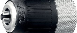
Features of disassembling the keyless chuck
The specific design of quick-release chucks does not allow for their complete disassembly. To lubricate the device, do the following:
Carefully pry the coupling around with a screwdriver.
- Remove the coupling by hand.
- Open your fists as much as possible.
- Insert a steel rod into the cartridge and knock the housing out of the plastic coupling.
After this, disassembly must be stopped, otherwise reassembly will be impossible. Removing both parts of the coupling is sufficient to allow lubricant access inside the device.
To assemble, you need to install the upper part of the coupling, hammer in the end lock washer (through a wooden plank) and install the lower part of the coupling by hand. After this, the cartridge is completely ready for use.
Self-assembly of the cartridge according to the drawings
Self-assembly does not take much time. This is a fairly simple process. The main thing is to understand the mechanism of operation of the device. As a last resort, you can order such miniature equipment from a professional turner. He will assemble any variation from the available parts. Homemade models cost significantly less than those ordered from production.
The frame is put on first. Installing the part makes it possible to secure the cartridge.
Installing the chuck itself on the spindle
The mechanism is being secured. Do not press or bore parts. At this stage, fastening occurs with previously prepared bolts of suitable size.
Consolidation
After checking the quality of the wrapping, the final assembly of the mechanism is carried out. The bolts are screwed using a wrench.
Tools are installed on a homemade cartridge. Carried out after checking the assembly with bolts.
Releasing the cartridge
Once the workpiece is screwed in, the frame is no longer needed. It is carefully removed.
It is imperative to check the functionality of the self-made mechanism. The product is placed in a lathe. Several smooth turns are made and the clarity of the fastening is checked. The specialist assesses the level of centralization and whether objects move.
Homemade cartridges must be periodically serviced. They are completely disassembled, the inside is cleaned, and then dried in the fresh air. Lubricated with regular oil. If the product is going to be stored, then this must be done according to the rules. Bend the fists into the central part, plug the hole tightly with a rag.
Such storage will ensure the integrity of the cartridge, since it cannot be damaged mechanically, and dust will not settle in the hole in the equipment structure. Before use, the old cartridge is lubricated and runs for up to 10 minutes at a smooth, slow speed.
Purpose
Inside the type of part in question is a cam mechanism. This important component allows you to center and clamp the workpiece. This happens due to the narrowing of the cam parts, and then clamping them with a quill. Only after the part has been completely secured can you begin working on a wood or metal lathe. If the procedure is not followed, the workpiece may not only fall out or be damaged, but also cause harm to the master.
You should carefully check the quality of fastening of the part in the chuck. First, specialists turn on the lathe at low power and see if the mechanism rotates well. If after a few laps everything is in order, they will continue to work at higher powers.
Types and purposes
Cams are divided into the following types:
- straight (parts are fixed from the outside);
- reverse (fastening from the inside of the part);
- overhead or “raw cams” (fixation of parts with a large diameter);
- prefabricated (racks, with hardened overhead cams).
Direct
Straight jaws are most often used to clamp parts. Each of them has two stages for fastening parts “for expansion” and one prism for “compression”.
The working platforms of the cam steps, into which the ends of the workpieces rest, serve to eliminate the end runout of the latter.
The following parts are attached using straight cams:
- small-sized (with the surface of the prisms - behind the outer side of the part);
- large-sized (usually hollow workpieces - the surface of the steps).
Reverse
In their design, reverse cams are the opposite of straight cams and are used for fastening “in compression” to the outer side of large-diameter parts.
The outer surface of the reverse cams can be used to install an additional fastening base that works to “unclamp” the inner surface of the workpiece.
Invoices
They are made directly by turners from steel or non-ferrous metals without additional heat treatment, and therefore are also called “raw cams”. They are attached to rails (supplied with the chuck), which are installed instead of direct or reverse cams.
Overhead jaws (“raw jaws”) are made in proportion to the shapes of the workpieces to ensure high centering accuracy.
Prefabricated
Prefabricated cams (universal, compound) consist of two parts:
- the bottom one is the same rack with combs (moves along a spiral disk);
- top – cover (with standard hardening of the working area).
The linings are cams - inversions (direct - reverse). They differ from overhead or “raw” cams in that they are subject to mandatory heat treatment.
To change the view, just unscrew two bolts on each “reversal”, turn it to the desired side and secure it to the rail with the same bolts.
The versatility of prefabricated jaws makes it possible to reduce the preparatory time for processing a part, if it is necessary to frequently change direct to reverse and vice versa.
This type of jaws causes an error due to the reinstallation of the “reversals” and for this reason they are used in lathe chucks with a diameter of 250 mm or more. The magnitude of the relative error here is not so significant, but the labor costs for reinstallation are reduced significantly.
By type of execution
In the Russian Federation, the types of cartridges by design are regulated by GOST 2675 - 80.
Whole
Made from a piece of steel with parameters starting from 500 MPa. The most common type.
Made
A rail is made of steel, and a cam is attached to it. The latter is made of metal.
Overhead
Composite variations consist of non-ferrous metal, stainless steel, ferrous metals. Used for working with large-scale projects.
Grinding
First, let's make sure that the cams really need grinding. Let's take a metal shaft and place part of it in a lathe chuck. Clamp the shaft with cams. During operation, you may notice that the cams are hitting the part. Therefore, they need care.
The inner plane of the cams is subjected to grinding. First you need to clamp the ring with your fists so that they do not unwind spontaneously. It is believed that the simplest method is grinding using a cutter with a special stone.
We install the frame with the stone on the cutter, turn on the lathe chuck and move the part with the stone along the plane of the cams. Due to rotation and contact with the stone, their surface will acquire the desired characteristics.
Why choose us?
- We use modern equipment. Our specialists have machines made in the USA and Japan at their disposal. They are equipped with a numerical control function, and therefore allow you to control production at every stage.
- We receive only high-quality materials from domestic and foreign suppliers. This allows us to reduce the lead time for each order and ensure the proper quality of manufactured parts.
- You can pay for your order by bank transfer or by bank receipt. We give you the opportunity to use staged payments or apply for a deferment.
To use our services for the production of various parts, leave a request on our website, request a call back or contact us by phone in Moscow and. You can also personally contact our office and get advice from our specialists.