Load grippers | 01/11/2020
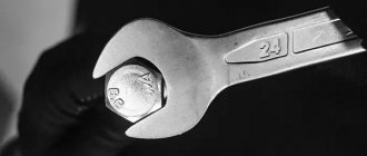
Eye bolts are a type of rigging fasteners designed to perform various tasks of lifting and moving loads. The technical requirements and range of these domestically produced products are regulated by GOST 4751-73. Products almost similar in size are also produced abroad according to DIN 580.
MAIN PARAMETERS AND DIMENSIONS
1.1. The design and main dimensions of the eye bolts must correspond to those indicated in the drawing and table. 1.
Table 1
Dimensions in mm
| Thread symbol d | Applicability | D1 | d2 | d3 | d4 | b | h | h1 | l | l 1, no less | r | r1 | Weight 1 piece, kg |
| M8 | 36 | 20 | 8 | 20 | 10 | 12 | 6 | 18 | 12 | 2 | 4 | 0,05 | |
| M10 | 45 | 25 | 10 | 25 | 12 | 16 | 8 | 21 | 15 | 0,12 | |||
| M12 | 54 | 30 | 12 | 30 | 14 | 18 | 10 | 25 | 19 | 6 | 0,19 | ||
| M16 | 63 | 35 | 14 | 36 | 16 | 20 | 12 | 32 | 25 | 0,31 | |||
| M20 | 72 | 40 | 16 | 40 | 19 | 24 | 14 | 38 | 29 | 3 | 8 | 0,50 | |
| M24 | 90 | 50 | 20 | 50 | 24 | 29 | 16 | 45 | 35 | 12 | 0,87 | ||
| M30 | 108 | 60 | 24 | 63 | 28 | 37 | 18 | 55 | 44 | 15 | 1,58 | ||
| M36 | 126 | 70 | 28 | 75 | 32 | 43 | 22 | 63 | 51 | 4 | 18 | 2,43 | |
| M42 | 144 | 80 | 32 | 85 | 38 | 50 | 25 | 72 | 58 | 20 | 3,72 | ||
| M48 | 162 | 90 | 36 | 95 | 42 | 52 | 30 | 82 | 68 | 22 | 5,54 | ||
| M56 | 180 | 100 | 40 | 105 | 48 | 60 | 34 | 95 | 78 | 5 | 25 | 8,09 | |
| M64 | 198 | 110 | 44 | 115 | 52 | 65 | 40 | 110 | 93 | 10,95 | |||
| М72×6 | 234 | 130 | 52 | 135 | 62 | 75 | 45 | 115 | 98 | 35 | 18,54 | ||
| M80×6 | 270 | 150 | 60 | 160 | 70 | 88 | 50 | 125 | 108 | 25,40 | |||
| M100×6 | 324 | 180 | 72 | 190 | 85 | 105 | 60 | 150 | 133 | 40 | 43,82 |
An example of a symbol for an eyebolt with M8 thread without coating:
Eye bolt M8 GOST 4751-73
The same, with fine thread M100×6, with coating 01 (zinc with chromating), thickness 9 microns:
Eye bolt M100×6.019 GOST 4751-73
(Changed edition, Amendment No. 1, 2).
1.2. The lifting capacity of the eye bolts must correspond to those indicated in the table. 2.
table 2
| Thread symbol | Load capacity per 1 eye bolt, kg, + | ||
| when directing the slings | |||
| along the vertical axis of the eye bolt | at an angle of 45º from the vertical axis of the eye bolt | ||
| in the plane of the ring | with deviation from the plane of the ring | ||
| M8 | 120 | 80 | 40 |
| M10 | 200 | 125 | 65 |
| M12 | 300 | 175 | 90 |
| M16 | 550 | 250 | 125 |
| M20 | 850 | 325 | 150 |
| M24 | 1250 | 500 | 250 |
| M30 | 2000 | 700 | 350 |
| M36 | 3000 | 1000 | 500 |
| M42 | 4000 | 1300 | 650 |
| M48 | 5000 | 1650 | 800 |
| M56 | 6200 | 2000 | 1000 |
| M64 | 7500 | 2500 | 1250 |
| М72×6 | 10000 | 3500 | 1750 |
| M80×6 | 14000 | 4500 | 2250 |
| M100×b | 20000 | 6500 | 3250 |
Notes:
1. When lifting a load, the direction of the slings at an angle from the vertical axis of the eyebolt of more than 45° is not allowed.
2. To install in the same plane the rings of two eyebolts screwed in until they stop, it is allowed to use flat washers with a thickness of:
- up to 1 mm - for eye bolts with M8-M12 thread;
- no more than half the thread pitch - for eye bolts with threads over M12.
1.3. The design and dimensions of the sockets for eye bolts are given in the Appendix.
TECHNICAL REQUIREMENTS
2.1. Eye bolts must be made of steel grade 20 or 25 (subgroup a) according to GOST 1050-88 by stamping. Production by forging is allowed.
Compliance of the material with the prescribed grades must be confirmed by a certificate from the metal manufacturer.
(Changed edition, Amendment No. 1).
2.2. (Deleted, Amendment No. 1).
2.3. Technical requirements for stamped forgings in accordance with GOST 7505-89, accuracy class - II, degree of complexity - C3.
Note. When producing eye bolts by free forging in backing dies, it is allowed to increase the plus tolerances by 2 times.
(Changed edition, Amendment
No. 1).
2.4. A flat on the inner circumference of the ring is allowed, resulting from deburring, provided that the size is maintained within the tolerances of clause 2.3.
2.5. Welding or sealing of defects is not allowed.
2.6. Eye bolts after stamping or forging must be normalized and free of scale.
2.7. The hardness of normalized eye bolts must correspond to that indicated in the table. 3.
Table 3
| steel grade | Hardness of HB eye bolts with thread size | |
| from M8 to M64 | from M72×6 to M100×6 | |
| 20 | 105-149 | 95-121 |
| 25 | 134-187 | 105-149 |
One repeated heat treatment is allowed.
2.8. Center holes are not allowed on the eyebolt ring.
2.9. Cuts on the machined part of the shank are not allowed.
2.10. Thread - according to GOST 24705 with a tolerance range of 8 g
according to GOST 16093.
Dimensions of chamfers and thread runs - according to GOST 10549-80. The amount of thread run-out for the angle of the tool intake is 20°.
Note. When applying the coating, the specified dimensions and roughness must be ensured.
2.11. The thread should not have broken threads, burrs or dents.
2.12. Thread axis perpendicularity tolerance d
at a length of 100 mm relative to the reference plane of the ring:
0.10 mm - for eye bolts with threads from M8 to M16;
0.05 mm - for eye bolts with threads from M20 to M100×6.
2.13. Thread axis symmetry tolerance d
relative to the general planes of symmetry of the eye bolt:
T 1 mm - for eye bolts with threads from M8 to M12;
T 2 mm - for eye bolts with threads from M16 to M48;
T 4 mm - for eye bolts with threads from M56 to M100×6.
2.12 - 2.13. (Changed edition, Amendment
No. 2).
2.14. Eyebolts must withstand a strength test with a load equal to twice the rated load capacity.
The permissible deviation of this load is ±5%.
2.15. Eye bolts can be manufactured with a coating. Types and symbols of coatings - according to GOST 1759.0-87.
Technical requirements for coatings and surface quality of eye bolts before coating are in accordance with GOST 9.301-86.
(Changed edition, Amendment No. 1).
ACCEPTANCE RULES
3.1. The manufacturer must conduct acceptance tests of eye bolts. During acceptance tests, eye bolts are checked:
before machining
— for compliance with the requirements of clause 1.1 in terms of dimensions obtained by stamping or forging and clauses. 2.3, 2.4: in the case of production by open forging in backing dies - each eye bolt; in the case of production by volumetric stamping - 5% of the batch, but not less than 5 pieces;
— for compliance with the requirements of paragraphs. 2.5 and 2.6 each eye bolt;
— for compliance with the requirements of clause 2.7 10% of the lot, but not less than 5 pieces; after machining:
— for compliance with the requirements of clause 1.1 (dimensions l
,
l
1 and
h
l and
d
) pp. 2.8 - 2.14 each eye bolt;
— for compliance with the requirements of clause 2.15 — according to GOST 9.301-86.
Note. The batch consists of eye bolts of the same size, made of steel of the same grade, and heat treated together.
(Changed edition, Amendment
No. 1).
3.2. If unsatisfactory test results of eye bolts are obtained according to at least one of the indicators, repeated tests are carried out on a double number of samples; taken from the same party, in full. The results of repeated tests are final and apply to the entire batch.
(Introduced additionally, Amendment No. 2).
LABELING, PACKAGING, TRANSPORTATION AND STORAGE
5.1. Each eye bolt on the generatrix of the supporting part of the ring must have the following markings: - trademark of the manufacturer; - symbol of thread. For eye bolts with M8-M16 threads, it is allowed to mark only the trademark of the enterprise; in this case, the thread symbol is marked on the batch tag.
5.2. Marking is done by pressure or stamping. Impact marking is allowed.
5.3. Eye bolts are packed in dense wooden non-separable boxes in accordance with GOST 2991, lined inside with packaging paper grade B in accordance with GOST 515.
5.4. Eye bolts from one batch are packed into each box.
5.5. The gross weight of each box should not exceed 60 kg.
5.6. Conservation - according to GOST 9.014.
5.7. Each batch of eye bolts must be accompanied by a document containing: - the name or trademark of the manufacturer; — symbol of eye bolts; — number of eye bolts; — results of control tests.
5.8. Marking of transport containers is in accordance with GOST 14192.
5.9. Each box is marked with: - trademark of the manufacturer; — symbol of eye bolts; — gross and net in kilograms.
TEST METHODS
4.1. Compliance with the requirements of clause 2.3 is checked by external inspection without the use of magnifying devices.
Magnifiers up to three times magnification can be used.
(Changed edition, Amendment No. 2).
4.2. Hardness (clause 2.7) is determined according to GOST 9012-59 on the generatrix of the supporting part of the ring.
4.3. The threads (clause 2.10) are checked with maximum gauges.
4.4. The deviation from the perpendicularity of the axis of the threaded shank to the supporting surface of the ring (clause 2.12) is checked with an angle template or feeler gauge along the clearance between the supporting surface of the ring and the end surface of the control gauge.
4.5. Compliance of eye bolts with the requirements of clause 2.4 is checked by a tensile test with holding under load for 10 minutes.
The load must be applied along the axis of the eyebolt rod.
The application of the load should be smooth, without jerking.
After removing the load, there should be no residual deformation, cracks or tears in the eye bolts.
The absence of residual deformations is determined by checking the dimensions along the axis of the eye bolts before and after testing.
The absence of cracks and tears is checked by external inspection using a magnifying glass with at least four times magnification.
4.6. The thickness of the coating layer (clause 2.15) is checked on the eyebolt ring. Methods for checking the quality and thickness of the coating are in accordance with GOST 9.302-88.
4.7. (Deleted, Amendment No. 2).
GOST 4751-73
GOST 4751-73 S. 5
— for compliance with the requirements of paragraphs. 2.5 and 2.6 each eye bolt:
— for compliance with the requirements of clause 2.7 10% of the lot, but not less than 5 pieces;
after machining:
— for compliance with the requirements of clause 1.1 (dimensions I, /, and A, and J) clauses. 2.S—2.14 each eye bolt:
— for compliance with the requirements of clause 2.15 — according to GOST 9.301.
11 r i m c h a n i s. The batch consists of eye bolts of the same size, made of steel and the same grade, jointly heat treated.
(Changed edition, Amendment No. 1).
3.2. If unsatisfactory test results for eye bows are obtained according to at least one of the indicators, repeated tests are carried out on a double number of samples taken from the same batch, according to the full program. The results of repeated tests are final and apply to the entire batch.
(Introduced additionally, Amendment No. 2).
4. TEST METHODS
4.1. Compliance with the requirements of clause 2.3 is checked by external inspection without the use of magnifying devices.
Magnifiers up to three times magnification can be used.
(Changed edition, Amendment No. 2).
4.2. Hardness (clause 2.7) is determined according to GOST 9012 on the generatrix of the supporting part of the ring.
4.3. The threads (clause 2.10) are checked with maximum gauges.
4.4. The deviation from the perpendicularity of the axis of the threaded shank to the supporting surface of the ring (clause 2.12) is checked with an angle template or feeler gauge along the clearance between the supporting surface of the ring and the end surface of the control gauge.
4.5. Compliance of eye bolts with the requirements of clause 2.4 is checked by a tensile test with holding under load for 10 minutes.
The load must be applied along the axis of the eyebolt rod.
The application of the load should be smooth, without jerking.
After removing the load, there should be no residual deformation, cracks or tears in the eye bolts.
The absence of residual deformations is determined by checking the dimensions along the axis of the eye bolts before and after testing.
The absence of cracks and tears is checked by external inspection using a magnifying glass with at least four times magnification.
4.6. The thickness of the coating layer (clause 2.15) is checked on the eyebolt ring. Methods for checking the quality and thickness of the coating are in accordance with GOST 9.302.
4.7. (Deleted, Amendment No. 2).
5. LABELING, PACKAGING, TRANSPORTATION AND STORAGE
5.1. Each eye bolt on the forming support part of the ring must be marked as follows:
— trademark of the manufacturer;
- symbol of thread.
For eye bolts with M8-M16 threads, it is allowed to mark only the trademark of the enterprise: in this case, the symbol of the thread is marked on the batch tag.
5.2. Marking is done by pressure or stamping. Impact marking is allowed.
5.3. Eye bolts are packed in dense wooden non-separable boxes in accordance with GOST 2991, lined inside with packaging paper grade b in accordance with GOST 515.
5.4. Eye bolts from one batch are packed into each box.
5.5. The gross weight of each box should not exceed 60 kg.
5.6. Conservation - according to GOST 9.014.
5.7. Each batch of eye-butts must be accompanied by a document containing:
— name or trademark of the manufacturer;
APPENDIX (Recommended) EYE BOLTS SOCKETS
1. The design and dimensions of sockets for eye bolts in products made of ferrous metals must correspond to those indicated in the drawing and table.
mm
| Thread symbol d | d 1 | h | l , no less | Thread symbol d | d 1 | h | l , no less |
| M8 | 13 | 5 | 19 | M42 | 52 | 14 | 74 |
| M10 | 15 | 6 | 22 | M48 | 60 | 84 | |
| M12 | 17 | 26 | M56 | 68 | 17 | 97 | |
| M16 | 22 | 7 | 33 | M64 | 75 | 112 | |
| M20 | 28 | 9 | 39 | М72×6 | 85 | 117 | |
| M24 | 32 | 10 | 47 | M80×6 | 95 | 127 | |
| M30 | 38 | 11 | 57 | M100×6 | 115 | 152 | |
| M36 | 45 | 12 | 65 |
(Changed edition, Amendment
No. 2, 4).
2. Thread - according to GOST 24705 with a tolerance range of 7H
according to GOST 16093.
The thread should not have broken threads.
3. Perpendicularity tolerance of thread axis d
at a length of 100 mm relative to the supporting surface of the socket:
0.2 mm - for eye bolts with threads from M8 to M16;
0.1 mm - for eye bolts with threads from M20 to M100×6.
(Changed edition, Amendment No. 2, 3).
4. Sockets for eye bolts must be clean, without holes or undercuts.
5. The size of the supporting flat surface of the socket, having a roughness designation of Ra12.5 microns, must be no less than the diameter of the supporting surface of the eye bolt.
(Changed edition, Rev.
№ 1, 4).
Dimensions
An eye bolt includes a closed steel ring of certain internal and external diameters, a rod, on the predominant part of which a metric thread is cut (or rolled), as well as a transition part (it connects the ring to the rod through cast or stamped radius transitions).
Size range of eye bolts according to GOST 4751-73:
- The range of thread diameters is from M8 to M100 (the most common threads are M8, M10, M12 and M16).
- Inner diameter of the ring, mm – 20…180.
- Outer diameter of the ring, mm – 36…324.
- Rod length, mm, not less – 12…133.
To eliminate stress concentrators, all transitions between elements of the fastener configuration are made along radii. Eye bolts can be manufactured with anti-corrosion (zinc or chrome) coating.
The thread on the rod of the product can be with a large or small pitch (the production of threads with a fine pitch is negotiated when ordering individually).
INFORMATION DATA*
1. APPROVED AND ENTERED INTO EFFECT by Resolution of the State Committee of Standards of the Council of Ministers of the USSR dated May 10, 1973 No. 1169
2. Verification period
- 1993, frequency - 5 years.
3. INSTEAD GOST 4751-67
4. REFERENCE REGULATIVE AND TECHNICAL DOCUMENTS
| Designation of the referenced technical document | Item number |
| GOST 9.014-78 | 5.6 |
| GOST 9.301-86 | 2.15, 3.1 |
| GOST 9.302-88 | 4.6 |
| GOST 515-77 | 5.3 |
| GOST 1050-88 | 2.1 |
| GOST 1759.0-87 | 2.15 |
| GOST 2991-85 | 5.3 |
| GOST 7505-89 | 2.3 |
| GOST 9012-59 | 4.2 |
| GOST 10549-80 | 2.10 |
| GOST 14192-96 | 5.8 |
| GOST 15150-69 | Introductory part |
| GOST 16093-81 | 2, application |
| GOST 24705-81 | 2, application |
5. Tested in 1988. The validity period was removed by Decree of the USSR State Standard of December 16, 1988 No. 4162
6. REISSUE (June 1998) with Amendments No. 1, 2, 3, 4, approved in May 1979, January 1983, December 1988, August 1990 (IUS 7-79, 5-83 , 3-89, 11-90)
Reissue
(as of April 2008)
* See notes from FSUE STANDARDINFORM (p. 8).
