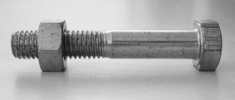
Bolt accuracy
Another important property is accuracy. Manufacturers produce products in two accuracy classes
Class A - implies that the rod fits into the hole with minimal clearance. The diameter of the mounting hole cannot be 0.3 mm greater than the thickness of the bolt. This kind of precision is quite easy to achieve on a production floor, but almost impossible on a construction site. Class B and C fasteners can be installed in mounting holes larger than the product rod by 2 - 3 mm.
The precision of a bolted connection has a significant impact on its strength and load resistance. In particular, the more accurately the mounting hole is made, the less will be the impact of loads arising perpendicular to the axis of the rod.
Rating: /5 — votes
Marking of bolts and screws
Most often, bolts are marked on the end surface of the head, under the manufacturer's mark. The numbers can be convex or deep. Sometimes there is no dot between the numbers, for example 10.9 is written as 109. If the designation is underlined (like this: 10.9 or 109), this means that the bolt is made of low-carbon martensitic steel. Some factories mark bolts with special symbols - a dot and a dash (dial marking). The dot serves as a guide and is located at 12 o'clock, and the position of the single or double dash indicates the strength class: If there is no marking, then the bolt has a strength class of 6.8 or lower.
Bolt strength
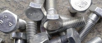
All bolts with threads greater than M6 must be marked. The strength of the bolts according to GOST or ISO, as well as their design, is marked on the bolt head. If the thread of a bolt or screw is larger than M6, and there is no marking on the head, then the use of such a bolt should be abandoned. Let's look at what the bolt strength class means and how it is indicated directly on the head.
The picture shows three types of markings. Bolt strength 8.8 is the most common. A bolt of strength class 10.9 is, accordingly, more durable than 8.8. The “X” designation on the bolt head indicates that the bolt is hardened; as a rule, this designation is found on cardan bolts. There are bolt strength classes 3.6, 4.6, 4.8, 5.6, 5.8, 6.6, 6.8, 8.8, 9.8, 10.9, 12.9. There may be no dot between the numbers.
Now let's talk about what these numbers mean. The first number of the marking is equal to 0.01 of the tensile strength of the bolt. To understand the tensile strength, divide the first number by 0.01 and get the tensile strength in MPa. The second number is equal to 0.1 of the ratio of the bolt's yield strength to its tensile strength. If we multiply the numbers and multiply the result by 10, we get the yield strength in MPa. Let's give an example of decoding. The strength of bolt 12.9 is deciphered as follows:
12/0.01 = 1200 (MPa) – tensile strength.
12x10x9 = 1080 (MPa) – yield strength.
Bolts of strength class up to 5.6 are most often used in furniture production, the rest are used in mechanical engineering and construction. Moreover, strength classes 10.9 and 12.9, due to the high price, are used when assembling particularly critical components.
In addition to standard hex head bolts, there are also socket head screws, flange head bolts, pan head and square head bolts, and others. The location of the markings on such bolts differs from standard bolts. The marking can be applied to a cylindrical surface or under the head of a bolt.
The picture shows examples of marking on a bolt with a semicircular head (left) and on a bolt with an internal hexagon (right).
There are also bolts designed for use in certain assemblies; they may have additional markings. For example, bolts for bridge construction may be marked “ХЛ”, which means the bolt can be used at temperatures up to – 65 0 C. Sometimes the grade of steel used in manufacturing is indicated on the bolt heads.
The strength class is also indicated on the studs; it is applied to the cylindrical part where there is no thread, but with two significant differences: 1) On bolts, the marking protrudes above the surface, on studs, on the contrary, the marking goes deep into the material. 2) Studs are marked, starting with strength class 5.6. On stud diameters less than M12, sometimes they are marked not with numbers, but with symbols, each of which corresponds to a strength class.
Nuts are marked according to a slightly different principle. When marking a nut, take into account the ratio of its height to the thread diameter. According to the ratio of nut height to diameter, nuts are divided into 5 types: 1) Low N/d less than 0.8 2) Normal with a ratio of height to thread diameter of 0.8 3) High with a ratio of 1.2 4) Extra high with a ratio of 1. 5. 5) Ultra-low, markings are usually not applied to them.
For low nuts, there are only two strength classes - 04 and 05. To calculate the tensile strength, remove 0 and multiply by 100. We get 400 and 500 MPa, respectively. Based on the obtained value, we determine which bolt strength class the nut should be used with.
Normal, high and extra high nuts have 7 strength classes - 4, 5, 6, 8, 9, 10, 12. Similarly, multiply by 100 and get the tensile strength value. Thus, a nut of strength class 8 is best used with a bolt of 8.8. In this case, the load distribution in the thread will be uniform.
Sometimes there are other markings on the bolts, but, as a rule, this happens very rarely. The vast majority of bolts are marked according to this principle.
In the next article I will tell you how to calculate a bolt for tension, shear and collapse.
Ask questions, leave comments, share your impressions of the article!
Material hardness
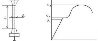
Brinell hardness is a characteristic that allows you to determine the hardness of a material.
Stainless steel fasteners are also equipped with special markings on the top of the fastener.
Type of steel A2 or A4 and tensile strength - 50, 70, 80, examples: A2-70, A4-80. Fasteners that have a clearly defined thread are color-coded for A2 in green and for A4 in red. The value for the yield strength is not specified.
For example, a value of 70 is the most standard and demonstrates the maximum strength of stainless steel fasteners.
Maximum fluidity for stainless steel hardware, often only a reference value.
The fluidity in this case will be 250 N/mm2 for A2-70 and about 300 N/mm2 for A4-80.
The approximate increase will be no more than 40%. In other words, this type of steel perfectly changes shape before irreparable deformation occurs.
Old domestic measurement methods according to GOST did not allow paying due attention to the maximum permissible loads on bolts, so the produced hardware was significantly lower in quality compared to modern ones.
An example to calculate the load on a material as accurately as possible using strength classification:
M12 fastening with strength 8.8, size d2 = 10.7 mm and maximum section length 89.87 mm2. In this case, the maximum permissible degree of load will be: (8*8*10)*89.87;0) = 57520 Newton.
Load chart for carbon steel and stainless steel bolts.
| ST-4.6 | ST-8.8 | A2-70 | A4-80 | |||||||
| THREAD | d2, mm | Area 62, tt2 | Max. load, Newton | Working load, kg | Max. load, Newton | Working load, kg | Max. load, Newton | Working load, kg | Max. load, Newton | Working load, kg |
| M1 | 0,8 | 0,5 | 121 | 0 | 322 | 10 | 126 | 0 | 151 | 0 |
| M2 | 1,7 | 2,27 | 544 | 20 | 1 452 | 70 | 567 | 20 | 681 | 30 |
| M3 | 2,6 | 5,31 | 1 274 | 60 | 3 396 | 160 | 1 327 | 60 | 1 592 | 70 |
| M4 | 3,5 | 9,62 | 2 308 | 110 | 6 154 | 300 | 2 404 | 120 | 2 885 | 140 |
| M5 | 4,4 | 15,2 | 3 647 | 180 | 9 726 | 480 | 3 799 | 180 | 4 559 | 220 |
| M6 | 5,3 | 22,05 | 5 292 | 260 | 14 112 | 700 | 5 513 | 270 | 6 615 | 330 |
| M8 | 7,1 | 39,57 | 9 497 | 470 | 25 326 | 1 260 | 9 893 | 490 | 11 872 | 590 |
| M10 | 8,9 | 62,18 | 14 923 | 740 | 39 795 | 1 980 | 15 545 | 770 | 18 654 | 930 |
| M12 | 10,7 | 89,87 | 21 570 | 1 070 | 57 520 | 2 870 | 22 469 | 1 120 | 26 962 | 1 340 |
| M14 | 12,6 | 124,63 | 29 910 | 1 490 | 79 761 | 3 980 | 31 157 | 1 550 | 37 388 | 1 860 |
| M16 | 14,6 | 167,33 | 40159 | 2 000 | 107 092 | 5 350 | 41 833 | 2 090 | 50199 | 2 500 |
| M20 | 18,3 | 262,89 | 63 093 | 3 150 | 168 249 | 8 410 | 65 722 | 3 280 | 78 867 | 3 940 |
| M24 | 21,9 | 376,49 | 90 359 | 4 510 | 240 956 | 12 040 | 94 123 | 4 700 | 112 948 | 5 640 |
| M27 | 24,9 | 486,71 | 116 810 | 5 840 | 311 493 | 15 570 | 121 677 | 6 080 | 146 012 | 7 300 |
| M30 | 27,6 | 597,98 | 143 516 | 7170 | 382 708 | 19130 | 149 495 | 7 470 | 179 394 | 8 960 |
Supplemented table of maximum loads on stainless materials and high-strength connections.
To be sure of the safety of the load, you can, without a twinge of conscience, divide the load in Newtons by thirty.
| Stainless steel A2-50 | |||||||
| THREAD | d2, mm | Area d2, mm2 | Yield strength, MPa | Max. load, Newton | Working load, kg | ||
| M1 | 0,8 | 0,50 | 200 | 100 | 0 | ||
| M2 | 1.7 | 2,27 | 200 | 454 | 20 | ||
| M3 | 2,6 | 5,31 | 200 | 1 061 | 50 | ||
| M4 | 3,5 | 9,62 | 200 | 1 923 | 90 | ||
| M5 | 4,4 | 15,20 | 200 | 3 040 | 150 | ||
| MB | 5,3 | 22,05 | 200 | 4 410 | 220 | ||
| M8 | 7,1 | 39,57 | 200 | 7 914 | 390 | ||
| M10 | 8,9 | 62,18 | 200 | 12 436 | 620 | ||
| M12 | 10,7 | 89,87 | 200 | 17 975 | 890 | ||
| M14 | 12,6 | 124,63 | 200 | 24 925 | 1 240 | ||
| M16 | 14,6 | 167,33 | 200 | 33 466 | 1 670 | ||
| M20 | 18,3 | 262,89 | 200 | 52 578 | 2 620 | ||
| M24 | 21,9 | 376,49 | 200 | 75 299 | 3 760 | ||
| M27 | 24,9 | 486,71 | 200 | 97 342 | 4 860 | ||
| MLO | 27,6 | 597,98 | 200 | 119 596 | 5 970 | ||
| Stainless steel A2-70 | |||||||
| THREAD | 62.mm | Area d2, mm2 | Yield strength, MPa | Max. load, Newton | Working load, kg | ||
| M1 | 0,8 | 0,50 | 250 | 126 | 0 | ||
| M2 | 1,7 | 2,27 | 250 | 567 | 20 | ||
| M3 | 2,6 | 5,31 | 250 | 1 327 | 60 | ||
| M4 | 3,5 | 9,62 | 250 | 2 404 | 120 | ||
| M5 | 4,4 | 15,20 | 250 | 3 799 | 180 | ||
| MB | 5,3 | 22,05 | 250 | 5 513 | 270 | ||
| M8 | 7,1 | 39,57 | 250 | 9 893 | 490 | ||
| M10 | 8,9 | 62,18 | 250 | 15 545 | 770 | ||
| M12 | 10,7 | 89,87 | 250 | 22 469 | 1 120 | ||
| M14 | 12,6 | 124,63 | 250 | 31 157 | 1 550 | ||
| M16 | 14,6 | 167,33 | 250 | 41 833 | 2 090 | ||
| M20 | 18,3 | 262,89 | 250 | 65 722 | 3 280 | ||
| M24 | 21,9 | 376,49 | 250 | 94 123 | 4 700 | ||
| M27 | 24,9 | 486,71 | 250 | 121 677 | 6 080 | ||
| MLO | 27,6 | 597,98 | 250 | 149 495 | 7 470 | ||
| Stainless steel A4-80 | |||||||
| THREAD | 12, mm | Area d2, mm2 | Yield strength, MPa | Max. load, Newton | Working load, kg | ||
| M 1 | 0,8 | 0,50 | 300 | 151 | 0 | ||
| M2 | 1,7 | 2,27 | 300 | 681 | 30 | ||
| M3 | 2,6 | 5,31 | 300 | 1 592 | 70 | ||
| M 4 | 3,5 | 9,62 | 300 | 2 885 | 140 | ||
| M 5 | 4,4 | 15,20 | 300 | 4 559 | 220 | ||
| MB | 5,3 | 22,05 | 300 | 6 615 | 330 | ||
| M 8 | 7,1 | 39,57 | 300 | 11 872 | 590 | ||
| M10 | 8,9 | 62,18 | 300 | 18 654 | 930 | ||
| M12 | 10,7 | 89,87 | 300 | 26 962 | 1 340 | ||
| M14 | 12,6 | 124,63 | 300 | 37 388 | 1 860 | ||
| M16 | 14,6 | 167,33 | 300 | 50199 | 2 500 | ||
| M20 | 18,3 | 262,89 | 300 | 78 867 | 3 940 | ||
| M24 | 21,9 | 376,49 | 300 | 112 948 | 5 640 | ||
| M27 | 24,9 | 486,71 | 300 | 146 012 | 7 300 | ||
| MLO | 27,6 | 597,98 | 300 | 179 394 | 8 960 | ||
4.2. Shear connections
4.2.1. When exposed to a longitudinal force passing through the center of gravity of the connection, the distribution of this force between the bolts should be assumed uniform. When a bending moment is applied to a connection, the distribution of forces between the bolts should be taken proportional to the distances from the center of gravity of the connection to the bolt in question (with triangular diagrams of the distribution of forces between the bolts, Fig. 2).
Rice. 2
4.2.2. Bolts that are sheared by the simultaneous action of a longitudinal force and a bending moment must be checked for the resultant force.
4.2.3. The design force (kN) that can be absorbed by one bolt should be determined using the formulas:
for cutting -
N
bs = 0.1
R
bs
γ
b1
A
n
b,(4 )
to crumple -
N
bp = 0.1
R
bp
γ
b1 γb2 γ(t)
a
b,(5)
Notations adopted in formulas (4, 5):
γ
b1 is the coefficient of working conditions, taking into account the non-simultaneous inclusion of bolts in work, which should be taken according to table. 4;
γ
b2 is the operating condition coefficient, taking into account the distances along the force from the edge of the element to the center of the nearest hole and between the centers of the holes, which should be taken according to table. 5;
A
=
nd
2/4 - design area, cross-section of the bolt rod, cm2;
n
b is the number of calculated cuts of one bolt;
γ(t) - coefficient taking into account the thickness of the elements being connected, determined
(6)
t
— the smallest total thickness of elements removed in one direction;
d
b is the nominal outer diameter of the bolt shaft, cm.
Table 4
| connection characteristics | Connection operating conditions coefficient γв1 |
| Single-bolt in shear and crush calculations | 1,0 |
| Multi-bolt in calculations for shear and crushing | 0,9 |
Table 5
| connection characteristics | Connection operating conditions coefficient γв2 |
| Single-bolt and multi-bolt based on crushing: | |
| at 1.5d ≤a | 0,25 a / |
| at a ≥ 3 | 1,25 |
Note.
Distance
b
must be greater than distance
a
by at least 0.5
d
.
Otherwise a
=
b
-0.5
d
.
The calculated forces that can be absorbed by one bolt of a multi-bolt connection per shear with one shear plane are given in.
Design forces that can be absorbed by one M24 bolt of a multi-bolt connection in collapse (at R
bp = 1.48·
R
un, a = 2
d
;
b
= 2.5
d
) are given in.
4.2.4. Number n
bolts in a connection under the action of axial force
N
(kN) should be determined by the formula
(7)
where Q
b is the lesser of the calculated forces for one bolt
N
bs and
N
bp, calculated in accordance with the requirements of these recommendations.
4.2.5. The crush movements of each element that occur during the operation of connections and from the action of standard loads should be determined:
a) at N
bp≤
N
bs - according to table.
6.
| Design collapse resistance R bp, MPa | Crumple movements of each connected element u , mm, from the action of standard loads at | ||||
| 1,0 | 1,1 | 1,2 | 1,3 | 1,4 | |
| 0,94 R un | 1,0 | 0,8 | 0,75 | 0,7 | 0,65 |
| 1,17 R un | 1,75 | 1,4 | 1,1 | 0,9 | 0,75 |
| 1,48 R un | 3,0 | 2,4 | 2,0 | 1,6 | 1,35 |
| 1,58 R un | 3,5 | 2,8 | 2,3 | 1,9 | 1,6 |
Designations adopted in table. 6:
Q
calc. — the force acting on the connection from the design loads;
Q
normal - the same from standard loads.
Note.
When determining the bearing displacements of each connected element for intermediate values
K
=
Q
calculated /
Q
norms, linear interpolation is allowed.
It is allowed to accept the values of the displacement of each connected element u
, from the action of standard loads less than those given in table. 6, while the design resistance of single-bolt connections to crushing should be determined by the formula
R
bp =
K
f
R
,
8
)
where f
— coefficient, equal to
f
= 1.08×
u
- at 0 u ≤ 0.8 mm, (9)
f
= 0.57+0.4×
u
-0.032×
u
2 - at 0.8
u
≤ 3.8 mm (10)
Factor f
depending on the displacements of the collapse of each connection of the element
u
is given in ;
b) at N
bs
N
bp - according to formulas 9, 10 and according to;
replacing N
bp in formula () with
N
bs.
4.2.6. The strength of elements weakened by holes in shear connections should be checked taking into account the complete weakening of the sections by holes.
Marking of high-strength bolts according to GOST R 52644-2006
And this is what the markings on the bolts look like according to the new GOST:
Marking values on the hex head of a high-strength bolt:
- 1. Manufacturer's mark;
- 2. Strength class for GOST R 52644-2006;
- 3. Climatic version HL (for cold climates);
- 4. Heat number;
- 5. The letter S is a designation for a high-strength hex head bolt with an increased wrench size
General overview
Metal fasteners manufactured in accordance with GOST standards differ in many parameters - from diameter and thread size to material class. The information necessary to understand the specifics of a particular product is applied to the head or cap. Before choosing, you need to calculate strength indicators, clarify the chemical composition and resistance to certain categories of substances, and also take into account special requirements related to operating conditions.