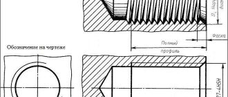
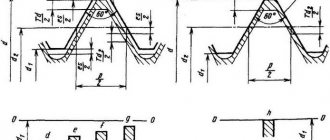
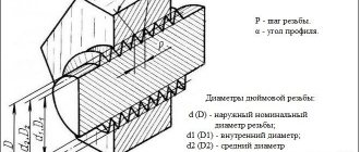
Single-start trapezoidal thread. Profile according to GOST 24737 (ST SEV 146)
d is the outer diameter of the external thread (screw); d2 - average diameter of external thread; D2 - average diameter of internal thread; P - thread pitch; h3 - height of the external thread profile; H4 - internal thread profile height; d3 - internal diameter of the external thread; D4 - outer diameter of the internal thread; R1 - rounding radius at the top of the external thread; R2 - radius of rounding along the root of the external and internal threads; ac is the clearance at the top of the thread.
In table 1 shows the dimensions of the thread profile .
Notes:
- Instead of rounding along the top of the external thread, it is allowed to make chamfers with a size of no more than 0.5 ac
- When rolling threads, make the profile of the thread root rounded. In this case, reduce the internal diameter of the external thread by 0.15R.
- Diameter values are calculated using the formulas:
D1=d-2H1=dP
D4=d+2ac
d3=D2=d-H1=d-0.5P
d3=d-2h3
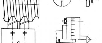
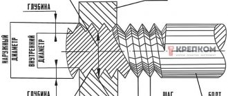
Thread pitch measurement
To measure the thread pitch, use a caliper or ruler. To do this, determine the length of several steps and divide it by the number of steps. The pitch of internal and external threads is determined by a thread gauge. Each plate indicates the step size. In this case, the plates are selected so that the teeth fit tightly into the thread. Thanks to this, the pitch coincides with the pitch on the plate.
To measure the thread pitch, standard rulers with millimeter and inch graduations and thread gauges are used. The results of calculating the pitch with a ruler are inaccurate, so the main task when taking measurements is to find the number of turns that fall on a single thread pitch. Let's say if there are 5 turns per 1 inch, the pitch will be 1/5 inch. For convenience, results in inches are converted to millimeters.
To measure the thread pitch correctly, you need to be aware of the following tricks:
- you should measure not individual sections, but the entire part of the part profile;
- before measurement it is necessary to count the whole number of turns;
- The thread pitch is determined after measuring the depth and basic parameters of the threaded connection.
The result of the measurements will be the average step value. The error in the calculations depends on how correctly the thread is cut on the part.
The thread gauge provides the most accurate pitch measurements for pipe and tapered threads because it works with the tightest distances. The design includes plates made of iron alloys. Each plate has cutouts equal to the cutting profile and its pitch.
To determine the pitch size, a thread gauge is applied to the part. In this case, it is necessary to ensure that the plate is parallel to the cutting axis and matches the size of the thread hole.
Single-start trapezoidal thread. Diameters and pitches according to GOST 24738 (ST SEV 639)
In table 2 shows thread diameters from 8 to 640 mm, the diameters are divided into two rows (row 1 and 2). When choosing a thread size, preference should be given to the first row. Preferred thread pitches are shown in bold.
Notes:
- The steps in bold are preferred when developing new designs.
- Steps marked * should not be used when developing new designs.
Measuring the average diameter of a thread
To measure the average diameter of a thread, you must use a thread micrometer complete with different tips (one with a cone, the other with a cutout). The measurement limit is usually indicated on the measuring instruments themselves. Thus, the marking M 3–5 means that the kit allows you to measure threads in increments of 3; 3.5; 4; 4.5 and 5 mm.
Inserts for thread micrometer
A micrometer is used to measure the average thread diameter. Replaceable tool tips are inserted into the screw hole and allow for the most accurate measurements.
If averaged values are sufficient as a result, calipers can be used instead of a micrometer. By design, it consists of ball tips, the dimensions of which must match the type and pitch of the threaded connection. To find out the average diameter, the tips of the calipers must be aligned with the thread gauge. Then the procedure is repeated with the sides of the part. Threaded clamps are used to evaluate measurement results. And the accuracy of the diameter is checked by comparing the resulting thread with the template.
To control the average diameter of a thread consisting of a maximum of two turns, use the two-wire method. The measurement is carried out as follows: wires, the diameter of which coincides with one of the tabular units, are placed on the opposite protrusions and recesses of the thread. In this case, the distance between the ends of the wires shows the average diameter of the part. For each accuracy class, separate wires are created that comply with GOST 2475-88. When deriving final numbers, possible errors are taken into account, because the two-delay method does not allow achieving accurate values.
Another method for measuring the average thread diameter is to use a microscope. The device is applied to the side of the workpiece profile, and the eyepieces are pointed at the profile image on each side to determine its size. The values obtained as a result of measurements are added and divided by the number of sides. The resulting arithmetic mean is the average diameter of the threaded connection.
Symbol for trapezoidal thread
The symbol for a trapezoidal single-start thread should include:
- letters Tr
- nominal thread diameter
- numerical value of the step
- letters LH for left-hand thread
An example of a symbol for a trapezoidal thread with a nominal diameter of 40 mm and a pitch of 6 mm:
Tr40×6
The same for left-hand thread:
Tr40×6LH
Related Pages
- Cylindrical threads
- Tapered threads
- Metric thread
- Runs, undercuts, grooves and chamfers according to GOST 10549
- Thread persistent
- Mechanical properties of bolts, screws, studs, nuts.
- Symbols of fasteners according to GOST 1759.0 (ST SEV 4203)
- General Purpose Hex Head Bolts
- General purpose screws
- Captive screws
- Set screws
- Special purpose bolts and screws
- Self-tapping screws for metal and plastics
- Locking the nut against the bolt with additional elements
- Locking the nuts relative to the body
- Locking the nut relative to the bolt due to additional friction, welding and plastic deformation
- Locking bolts. Preventing screws and nuts from being lost
- Locking screws
- Flange connection parts
- Flange connections for pipes and cylinder heads
- Flange connections for metal structure pipes
- Application examples for set screws
- Terminal connections
- Friction screw clamps
- Ties and stops
- Fastening machines to bases
Thread classification
Table 1.2.1
| № | Type | Profile | Conditional image | Standard | Examples | Examples |
| 1 | Metric | |||||
| 2 | Metric conical | |||||
| 3 | Pipe cylindrical | |||||
| 4 | Pipe conical | |||||
| 5 | Conical inch | — | ||||
| 6 | Trapezoidal | |||||
| 7 | Persistent | |||||
| 8 | Round |
1.2.1. Metric thread
Metric thread (see Table 1.2.1) is the main type of fastening thread. The thread profile is established by GOST 9150–81 and is an equilateral triangle with a profile angle α = 60°. The thread profile on the rod differs from the thread profile in the hole in the amount of blunting of its peaks and valleys. The main parameters of a metric thread are: nominal diameter - d(D) and thread pitch - P, established by GOST 8724–81.
According to GOST 8724–81, each nominal thread size with a large pitch corresponds to several small steps. Fine-pitch threads are used in thin-walled connections to increase their tightness, to carry out adjustments in precision mechanics and optics devices, to increase the resistance of parts to self-unscrewing. If the diameters and pitches of threads cannot satisfy the functional and design requirements, ST SEV 183–75 “Metric threads for instrument making” was introduced. If several step values correspond to one diameter, then the larger steps are used first. The diameters and pitches of threads indicated in brackets are not used if possible. In the case of using conical metric (see Table 1.2.1) threads with a taper of 1:16, the thread profile, diameters, pitches and main dimensions are established by GOST 25229–82. When connecting an external conical thread with an internal cylindrical thread according to GOST 9150–81, it must be ensured that the external conical thread is screwed in to a depth of at least 0.8.
1.2.2. Inch thread
Currently, there is no standard regulating the main dimensions of inch threads. The previously existing OST NKTP 1260 has been canceled, and the use of inch threads in new designs is not allowed. Inch threads are used when repairing equipment, since parts with inch threads are in use. The main parameters of an inch thread are: the outer diameter, expressed in inches, and the number of steps per inch of the length of the cut part of the part.
1.2.3. Pipe cylindrical thread
In accordance with GOST 6367–81, a cylindrical pipe thread has an inch thread profile, i.e. an isosceles triangle with an apex angle of 55° (see Table 1.2.1). The thread is standardized for diameters from 1/16" to 6" with a number of steps from 28 to 11. The nominal thread size is conventionally related to the internal diameter of the pipe (to the nominal diameter). Thus, a thread with a nominal diameter of 1 mm has a nominal diameter of 25 mm and an outer diameter of 33.249 mm.
Pipe threads are used to connect pipes, as well as thin-walled cylindrical parts. This type of profile (55°) is recommended for increased requirements for the tightness (tightness) of pipe connections. Pipe threads are used when connecting the cylindrical threads of the coupling with the conical threads of pipes, since in this case there is no need for various seals.
1.2.4. Pipe tapered thread
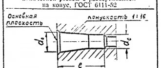
The parameters and dimensions of conical pipe threads are determined by GOST 6211–81, according to which the thread profile corresponds to the profile of an inch thread (see Table 1.2.1). The thread is standardized for diameters from 1/16″ to 6″ (in the main plane, the thread dimensions correspond to the dimensions of a cylindrical pipe thread). Threads are cut on a cone with a taper angle j/2 = 1°47'24" (as for metric tapered threads), which corresponds to a taper of 1:16. The thread is used for threaded connections of fuel, oil, water and air pipelines of machines and machine tools.
1.2.5. Trapezoidal thread
Trapezoidal thread has the shape of an isosceles trapezoid with an angle between the sides equal to 30° (see Table 1.2.1). The main dimensions of diameters and pitches of trapezoidal single-start threads for diameters from 10 to 640 mm are established by GOST 9481–81. Trapezoidal threads are used to convert rotational motion into translational motion under significant loads and can be single- and multi-start (GOST 24738–81 and 24739–81), as well as right and left.
1.2.6. Thrust thread
The thrust thread, standardized by GOST 24737–81, has a profile of an unequal trapezoid, one of the sides of which is inclined to the vertical at an angle of 3°, i.e. the working side of the profile, and the other at an angle of 30° (see Table 1.2.1) . The profile shape and pitch diameters for persistent single-start threads are established by GOST 10177–82. The thread is standardized for diameters from 10 to 600 mm with pitches from 2 to 24 mm and is used for large unilateral forces acting in the axial direction. 1.2.7. Round thread
Round threads are standardized. The profile of a round thread is formed by arcs connected to each other by sections of a straight line. The angle between the sides of the profile is α = 30° (see table 1.2.1). Threads are used to a limited extent: for water supply fittings, in some cases for crane hooks, and also under conditions of exposure to aggressive environments.
1.2.8. Rectangular thread
Rectangular threads (see Table 1.2.1) are not standardized, since, along with the advantages of a higher efficiency than trapezoidal threads, they are less durable and more difficult to manufacture. Used in the manufacture of screws, jacks and lead screws.
1.3. Conventional image of a thread. GOST 2.311–68
Constructing a helical surface in a drawing is a long and complex process, therefore, in product drawings, threads are depicted conditionally, in accordance with GOST 2.311–68. The helix line is replaced by two lines - a solid main line and a solid thin line. Threads are divided according to their location on the surface of the part into external and internal.
1.3.1. Conventional image of a thread on a rod
Fig.1.3.1.1
The external thread on the rod (Fig. 1.3.1.1) is depicted by solid main lines along the outer diameter and solid thin lines along the internal diameter, and in images obtained by projection onto a plane perpendicular to the axis of the rod, a thin line is drawn at 3/4 of the circle, and this the line can be open anywhere (it is not allowed to start a solid thin line and end it at the center line). The distance between the thin line and the solid main line should not be less than 0.8 mm and greater than the thread pitch, and the chamfer is not shown in this view. The thread boundary is applied at the end of the full thread profile (before the start of the run) with a solid main line, if it is visible. If necessary, the thread run-out is depicted as a solid thin line.
Fig.1.3.1.2?
For technological reasons, a part of the part (rod) may be under-threaded. In total, the undercut of the thread and the run-out represent an undercut of the thread (GOST 10548–80). The thread length is indicated, as a rule, without runoff.
1.3.2. Conventional image of a thread in a hole
Fig.1.3.2.1
Internal thread - depicted as a solid main line along the internal diameter and a solid thin line along the outer diameter. If, when depicting a blind hole, the end of the thread is located close to its bottom, then it is allowed to depict the thread to the end of the hole. Threads with a non-standard profile should be depicted.
1.3.3. Conventional image of the assembled thread
Fig.1.3.3.1
Sections of a threaded connection in the image on a plane parallel to its axis in the hole show only that part of the thread that is not covered by the thread of the rod. Hatching in sections and sections is carried out to a solid main line, i.e. to the outer diameter of the male thread and the internal diameter of the female thread.
1.4. Conventional representation of threads Table 1.4.1
| Type | Symbol | Dimensions in drawing | Designation on drawings | |||
| in images in a plane parallel to the thread axis | on images in a plane perpendicular to the thread axis | |||||
| on the rod | In the hole | on the rod | In the hole | |||
| Metric with large pitch GOST 9150-81 | M | Outer diameter (mm) | ||||
| Metric with fine pitch GOST 9150-81 | M | Outer diameter and thread pitch (mm) | ||||
| Trapezoidal single-thread GOST 9484-81 (ST SEV 146-78) | Tr | Outer diameter and thread pitch (mm) | ||||
| Pipe cylindrical GOST 6357-81 (ST SEV 1157-78) | G | Designation in inches | ||||
| Conical inch GOST 6111-52 | K | Designation in inches | ||||
| Pipe conical GOST 6211–81 (ST SEV 1159–78): external and internal | R Rc | Designation in inches | ||||
To designate threads, standards for individual types of threads are used. For all threads, except conical and cylindrical pipe threads, the designations refer to the outer diameter and are placed above the dimension line, on its extension or on the shelf of the leader line. The designations of conical threads and cylindrical pipe threads are applied only on the shelf of the leader line. Threads in the drawing are conventionally designated in accordance with standards for images, diameters, pitches, etc. Metric threads are designated in accordance with GOST 9150–81. Metric threads are divided into coarse pitch threads, designated by the letter M, indicating the nominal diameter of the cylindrical surface on which the thread is made, for example M12, and fine pitch threads, designated by indicating the nominal diameter, thread pitch and tolerance range, for example M24×2–6g or М12×1–6Н. When designating a left-hand thread, put LH after the symbol. Multi-start threads are designated, for example, three-start, M24×Z(P1)LH, where M is the type of thread, 24 is the nominal diameter, 3 is the thread stroke, P1 is the thread pitch. The given designations for left-handed and multi-start threads can be applied to all metric threads. Metric tapered thread is designated in accordance with GOST 25229–82. The thread designation includes the letters MK. Connections of internal cylindrical threads with external conical threads are used. The dimensions of the profile elements of conical and cylindrical threads are taken according to GOST 9150–81. A connection of this type must ensure screwing in a conical thread to a depth of at least 0.8l (where l is the length of the thread without running). The designation of an internal cylindrical thread consists of the nominal diameter, pitch and standard number (for example: M20×1.5 GOST 25229–82).
Fig.1.4.1
The connection of an internal cylindrical thread with an external conical thread (Fig. 1.4.1) is designated by the fraction M/MK, nominal diameter, pitch and standard number: M/MK 20×1.5LH GOST 25229–82. If there are no special requirements for the tightness of connections of this kind or when seals are used to achieve tightness of such connections, the standard number in the designation of connections is omitted, for example: M/MK 20×1.5 LH.
The tolerance field of the average diameter of the internal cylindrical thread must correspond to 6N according to GOST 16093–81, and the maximum deviation of the internal diameter and cut of the cavities of the internal cylindrical thread is accepted within the following limits: upper limit deviation (+0.12) -g- (+0.15), and the lower limit deviation is 0.
Pipe cylindrical thread. The thread symbol consists of the letter G, the designation of the thread size, the accuracy class of the average diameter (A or B). For left-hand threads, the designation LH is used. For example, G1½LH–В–40 make-up length, indicated if necessary.
The connection of an internal cylindrical pipe thread of accuracy class A with an external pipe conical thread according to GOST 6211–81 is designated as follows: for example, G/Rp–1½–A. When designating fits, the numerator indicates the accuracy class of the internal thread, and the denominator indicates the external thread. For example: G 1½–A/B.
Tapered pipe thread. The thread designation includes the letters: R - for tapered external thread, Rc - for tapered internal thread, Rp - for cylindrical internal thread and a designation of the thread size. For left-hand threads, the letters LH are added. The nominal size of the thread, as well as its diameters measured in the main plane, correspond to the parameters of a cylindrical pipe thread having the same nominal size. Therefore, parts with conical pipe threads are often used in connections with parts with cylindrical pipe threads, which ensures a fairly high tightness of the connections. Threaded connections are designated as a fraction, the numerator of which indicates the letter designation of the internal thread, and the denominator - the external thread. Example notation:
G/R * 1½ - A
internal pipe cylindrical thread of accuracy class A according to GOST 6357–81.
Trapezoidal thread. The symbol for a trapezoidal thread consists of the letters Tr, nominal diameter, stroke Pn and pitch P. For example: Tr20×4LH–8H, where LH is the designation of the left-hand thread, 8H is the main thread deviation.
If necessary, after the main thread deviation, the make-up length L (in mm) is indicated. For example: Tg40×6–8g–85; 85 – make-up length.
The thread is persistent. The thread designation consists of the letter S, nominal diameter, pitch and main deviation S80×10–8Н. For left-hand threads, the letters LH are indicated after the thread symbol. For multi-start threads, additionally enter the stroke value together with the letter P and the pitch value. Thus, a double-start thread with a pitch of 10 mm is designated S80 × 2 (P10).
Rectangular threads are not standardized. When depicting a rectangular thread, it is recommended to draw a local section on which the required dimensions are marked.
Special threads. If a thread has a standard profile, but differs from the corresponding standard thread in diameter or pitch, then the thread is called special. In this case, the inscription Sp is added to the thread designation, and the dimensions of the outer diameter and thread pitch are indicated in the thread designation, for example: Sp.M19×1D A thread with a non-standard profile is depicted as shown in paragraph 9 of Table 1, with dimensions applied necessary for making threads.
Cross-cut nut with spring
There is an option to extract the backlash by tensioning the nut halves with a spring. This method only works for a small load, since when the spring force is exceeded, it compresses and the unit begins to play. In this case, a spring with greater force cannot be installed, since friction losses will increase and the wear of the screw pair will increase.
If there are several pairs of such nuts, you can try to select pairs of half-nuts with the least amount of play, eliminating the spring from the design altogether. A screw/nut pair with a trapezoidal thread operates on sliding friction, has a large contact area and, as a result, high rigidity and low efficiency. On loaded large propellers, the presence of a characteristic “starting effect” (a jerk at the beginning of movement) is noticeable. Friction limits the speed of rotation of the propeller and therefore the speed of transmission, and also requires a more powerful engine. Due to the self-braking effect, the trapprop is well suited for moving loads vertically.
Nut misalignment
Acme screw nut misalignment
Skew adjustment is a very old method of adjustment. As the name implies, it is carried out by skewing the nut, then a gap is selected at two opposite edges of the nut (marked with a circle). It is quite simple to manufacture, but does not have a very long service life - the entire load falls only on small sections of the thread.
Acme screw nut cut across
Acme screw nut cut across
The nut halves are tightened or expanded relative to the cut, allowing for play, and then fixed relative to each other.
Cross-cut caprolon acme screw nut
There is also a version of a rectangular caprolon nut with a partial cut; the service life of such a nut is higher for both halves.
Measuring the internal diameter of a thread
The internal thread is measured using calipers. The tool is installed on a template part using a thread gauge, and then compared with the original internal diameter of the threaded connection. To obtain accurate values, the caliper must be positioned at an angle to the axis being measured.
You can also use cylindrical thread gauges to measure the internal diameter of a thread. This is because the inner diameter has a smooth surface and is ideal for the shape of the tips used in these instruments. The results obtained are checked using plug gauges.
Acme screw nut cut lengthwise
Acme screw nut cut lengthwise
The nut is cut lengthwise and its halves are closed on the lead screw. To adjust using this method, it is necessary that the threads do not touch the bottom of the mating parts, then when the halves of the half-nuts are compressed, the side parts of the thread trapezoids fit tighter and a gap is selected. Such split nuts and half nuts can be seen on the lead screws of universal lathes, where they are used as opening nuts. With this cutting method, the unit has the longest resource, since the axial force is distributed over the maximum area of the thread.