Purpose.
Rotating centers are used for positioning workpieces on various types of lathes, incl.
with CNC, for machining with high cutting speeds and loads. Available in two types:
- type A - with a permanent center roller;
- type B - with an attachment on the center roller.
Available in two versions:
- Spanish 1 — center roller with a 60° cone;
- Spanish 2 - center roller with a 60° cone, additionally machined to a 30° cone.
Rotating centers are manufactured according to GOST 8742-75.
An example of the designation of a center type A, version 1 with Morse taper 4, normal series of increased accuracy:
Center A-1-4-NP GOST 8742-75
Scope of application and features
Rotating centers are used in lathes for turning parts at rotation speeds of more than 75 m/min. At this speed, the process of increased wear of the center cone and the center hole of the workpiece begins. A partial way to solve the problem is to use lubricant and carbide tips, but the best option is to use a rotating center.
Main advantages of the equipment:
- Versatility. When using centers with replaceable attachments, parts with different conical axial holes can be processed.
- High load-bearing characteristics, significantly exceeding those of thrust clamps.
- Long service life due to reduced wear.
- Ability to work under high loads.
The main disadvantage is the presence of radial runout. This problem can be solved by using equipment with an acceptable runout indicator, or finishing at low speeds using a fixed center.
Specifications.
Radial runout of the center roller cone is no more than:
- for the normal series - 0.012 mm;
- for the normal series of increased accuracy - 0.006 mm;
- for the reinforced series - 0.016 mm.
The hardness of the center roller (nozzle) is not less than HRC 58. The hardness of the Morse taper of the shank is not less than HRC 45.
Normal series
| Designation | Morse cone | D | d | d1 - D1 | L | l | Maximum radial load, kgf |
| 7032-4158-00 | 2 | 51 | 22 | — | 151 | 30 | 40 |
| -01 | 3 | 63 | 25 | — | 177 | 33 | 65 |
| -02 | 4 | 71 | 28 | — | 203 | 35 | 100 |
| -03 | 5 | 80 | 32 | — | 250 | 45 | 220 |
Strengthened series
| Designation | Morse cone | D | d | d1 - D1 | L | l | Maximum radial load, kgf |
| 7032-4161-00 | 4 | 75 | 36 | — | 233 | 45 | 307 |
| -01 | 5 | 90 | 40 | 280 | 55 | 428 | |
| -02 | 6 | 125 | 56 | 357 | 70 | 740 |
Radial load data is based on 1000 rpm and a service life of 4000 hours.
Features of operation
Here are the basic rules for operating rotating centers necessary for precision machining of parts:
- When choosing the accuracy class of the equipment, it is necessary to leave a margin to cover runout errors due to other reasons - wear of bearings, low rigidity, etc.
- Correct installation of the part is important. The axis of the cone must coincide with the axis of rotation of the workpiece with high accuracy.
- To check the accuracy of the installation, you can place a white sheet of paper under the rotating center and evaluate the alignment. More precise control is carried out using indicators.
- If there is runout, the cone is ground in place and checked using a template. Processing is carried out with a power tool located in the tool holder.
- The beating of the rotating centers leads to the beating of the resulting part relative to the axis. When installing this part on another machine that has a different runout, a deviation from alignment may occur. To eliminate deviations, processing is carried out using a fixed center.
Operating procedure and maintenance.
4.1. Before installing the rotating center on the lathe, it must be unpreserved and the mobility of the axis must be checked. If necessary, lubricate the sliding surfaces of the rotating center (rolling bearings) with machine oil by pouring oil into the technological holes and rotating the center axis.
4.2. After the necessary checks and preparations, install the center into the tailstock quill of the lathe.
4.3. After finishing work, wipe the center with a soft cloth and lubricate it with anti-corrosion lubricant.
4.4. Operating conditions for the rotating center are GOST 15150-69 indoors in the absence of vapors of aggressive substances that cause corrosion of the product.
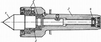
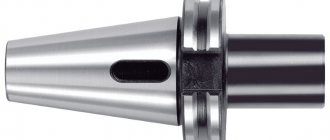
Design of rotating centers
The figure above shows the design of the center intended for fixing the tailstock quill of a lathe into the conical groove. The working part or center (1) rotates thanks to ball bearings (2) and (4); in other design options, needle bearings are used. The axial pressure arising during operation is compensated by the thrust ball bearing (5). Fastening in the quill is provided by a conical shank (3). To accurately determine axial forces, some designs have a built-in device.
More reliable fixation of workpieces, especially when working with heavy parts at high speeds, is ensured by centers built into the quill. This design, shown in the figure below, provides higher fixation rigidity, which is optimal when preparing large-section chips.
There is a specially bored hole in the front part of the quill (1). It contains bearings for the sleeve (4) - thrust (3) located in the front part to absorb axial load and radial (2). A conical hole is machined in the bushing for the center (5). This design can be used to attach a drill or any other axial tool, for which the sleeve is connected with a stopper to the quill.
History and evolution
Further in the text you will come across technical solutions that are effective, but little known to amateur craftsmen, because... in industry, for one reason or another, they are not used or are used to a limited extent. However, they can simplify and facilitate the manufacture of a homemade lathe for processing wood so much that in some cases it will be possible to limit the use of a power tool to a hand drill. The machine tool industry of the millennium is developing under the sign of solving the problem: how to make machine parts with an accuracy of, say, 1 conventional unit of length on a machine with an accuracy of, say, 0.2 of the same units? Etc. To understand how technology came to such a life, it will be useful to briefly turn to history.
The ancestor of all machines for processing materials by rotation is a device with which Neolithic people made fire and drilled horn, bone, stone, etc. 1 per rice; in the latter cases, an abrasive of wet quartz sand was added under a drill made of wood or bone. The primitive Celts, using the same principle, invented a foot-operated lathe, pos. 2; the centers were made from sharpened, burnt stakes of hard wood. In England, this unit is still used by furniture makers. The forest is not cut down there block by block. Having bought a couple of scaffoldings for felling, the master then carries armfuls of finished legs, balusters, etc. to the track. In a craft of this type, the machine survived for approx. until the beginning of the 18th century, pos. 3, although the workpiece rotates back and forth in it and the master has to be additionally distracted in order to turn the cutter over.
Stages of evolution of the wood lathe
In Ancient Egypt, already in the era of the Middle Kingdom, a lathe with a bow drive was well known, pos. 4. The “motor” was, naturally, the slave. In the Russian village community (in the world), with its strong traditions of mutual assistance and mutual assistance, the bow lathe survived in the outback until... the 80s of the last century! Mass individual wooden construction was in no way included in the five-year plans, but the Soviet leadership in the provinces turned a blind eye to unauthorized logging in limited quantities for their own needs or to unauthorized purchases of wild logs from timber industry enterprises for the universal Soviet currency of 40 volume. and a capacity of half a liter.
For fine and/or small work, a foot machine with a string and a bow machine were not suitable: there are always inhomogeneities in wood, and the workpiece itself was the flywheel - the damper of torsional vibrations. Radical improvements to the lathe were introduced by the master Theodore in Ancient Greece approx. in 400 BC uh, pos. 6. He supplemented the foot drive, firstly, with a crank - now the workpiece rotated in one direction. Secondly, I made the centers rotating and equipped one of them with a grip to hold the workpiece. Thirdly, he introduced a heavy flywheel into the kinematic scheme. Individual machines of this design were in operation at industrial enterprises before the start of electrification of industry, pos. 7 – given the complete absence of social guarantees at that time, the labor of an unskilled helper was cheaper than the cost of maintaining a steam engine.
Rotating center GOST 8742-75 fungal B-1-5-N with attachment. 32- 80
Add to comparison
| Select a center | B-1-2-N with nozzles. 25-60 |
Add to comparison
| Select a center | B-1-3-N with nozzles. Z0-70 |
Add to comparison
| Select a center | B-1-4-N with nozzles. Z0-70 |
Add to comparison
| Select a center | B-1-4-U with nozzles. Z0-70 |
Add to comparison
| Select a center | B-1-4-U with nozzles. 40-90 |
Add to comparison
| Select a center | B-1-5-U with attachment. 40- 90 |
Add to comparison
| Select a center | B-1-5-U with attachment. 90-130 |
Add to comparison
| Select a center | B-1-5-U with attachment. 130- 180 |
Add to comparison
| Select a center | B-1-5-U with attachment. 180- 240 |
Add to comparison
| Select a center | B-1-5-U with attachment. 240-290 |
Add to comparison
| Select a center | B-1-5-U with attachment. 290-340 |
Add to comparison
| Select a center | B-1-5-U with attachment. 340-390 |
Add to comparison
| Select a center | B-1-6-U with attachment. 40- 90 |
Add to comparison
| Select a center | B-1-6-U with attachment. 90-130 |
Add to comparison
| Select a center | B-1-6-U with attachment. 130-180 |
Add to comparison
| Select a center | B-1-6-U with attachment. 180-240 |
Add to comparison
| Select a center | B-1-6-U with attachment. 240-290 |
Add to comparison
| Select a center | B-1-6-U with attachment. 290-340 |
Add to comparison
| Select a center | B-1-6-U with attachment. 340-390 |
rezets-by.ru
Centers for lathes
The design of lathes requires the use of certain equipment. Only if you have the necessary equipment can you make a part with the required accuracy parameters. In this case, you need to purchase special equipment or make a homemade version. It is worth noting that you cannot create everything for precision turning with your own hands.
Turning rotary centers
Fixing workpieces
Turning on a lathe occurs by mounting it in a jaw chuck, which transmits rotation and at the same time holds it in place. Such a device is effective when turning cylindrical bodies. In this case, the cutter is fed perpendicularly, which allows the metal to be machined to the desired diameter.
When considering a metal lathe, keep in mind that many homemade and commercial versions have a structure at the back to support the workpiece and perform other tasks. A homemade type of metal lathe also has a headstock version, which requires special equipment.
Thus, when fixed on two opposite sides on the lathe, the tailstock and the headstock, the workpiece will be in the specified position during even heavy loads.
When considering the tailstock, the following features should be noted:
- The device in question is intended only for attaching special equipment. The types of equipment used on a lathe determine the purpose of the tailstock: it can serve both for fixing a cylindrical body and for processing.
- To ensure that the workpiece does not change its position at the time of strong feed or at high speeds, the center is used, which determines the purpose of the tailstock.
- You can make the center yourself or purchase it at a specialized store. When making it yourself, you need to take into account that the workpiece must be solid solid metal with an increased strength index. This is due to the fastening method: the quill presses the part against the spindle at the end and throughout the entire time the tip is in contact with it, slight friction occurs.
- The position of the lathe quill is adjustable only in the longitudinal direction. Given this feature, it is worth remembering that the position of the center must coincide with the axis of rotation of the spindle. Otherwise, rotations will occur with beating.
The device in question can also be used for drilling end holes and solving other technological problems.
Fixation at two ends occurs in the following cases:
- An industrial-type metal lathe has adjustable speed. The high rotation speed that is transmitted to the part leads to “wobble” of the part. With precision processing, according to GOST, this phenomenon leads to a fairly large error.
- The large length and weight of the workpiece also determines the need to use a tailstock. Under its own weight, the cylindrical body can be deformed and the cutter will “hit” the metal while feeding the cutter.
- Depending on the turning mode and spindle speed, excessive cross feed may occur. When processing a part in such a situation, it is quite difficult to make it with high accuracy.
In such cases, fixation should be carried out at both ends.
Types of turning centers
You can fix the necessary tool in the quill yourself. This job will take a few minutes to complete, and you can do it yourself. According to GOST, the following types can be distinguished:
- persistent. GOST determines that the tip and shank have almost the same diameter. The device of this design determines that the tip is made of hardened steel or hard alloy in accordance with GOST 13214-79.
- the fungal version is somewhat different from the previous one. According to GOST 8742-75, the fungal tip has a larger diameter with a truncated working cone. According to GOST 8742-75, there are two types of tips that the fungal center has: with a centered roller or with an attachment for it. The mushroom tip allows the device in question to be used for fastening rotating bodies with hollow end holes during processing.
Mushroom turning centerRotating turning centersThrust rotating centers
When turning under high centrifugal force, the most favorable conditions can be achieved by using a center whose design includes a bearing. Such equipment can be different: the mushroom or thrust center also has a bearing.
The cone angle can be 60 or 90 degrees. The angle is selected depending on the cutting mode.
There are more complex types of equipment for installation in quills, which may have, for example, a device for measuring downforce. It is impossible to make some versions of centers for a lathe with your own hands. Reverse spindle motion does not affect the ability to use the quill.
Download GOST 8742-75 “Rotating turning centers”
Download GOST 13214-79 “Centers and half-centers for turning”
, please select a piece of text and press Ctrl+Enter.
(: 1, average: 5.00 out of 5) Loading…
Source: https://StankiExpert.ru/tehnologicheskaya-osnastka/prisposobleniya/centry-dlya-tokarnykh-stankov.html
Rotating center GOST 8742-75 fungal B-1-5-U with nozzle. 40- 90
Add to comparison
| Select a center | B-1-2-N with nozzles. 25-60 |
Add to comparison
| Select a center | B-1-3-N with nozzles. Z0-70 |
Add to comparison
| Select a center | B-1-4-N with nozzles. Z0-70 |
Add to comparison
| Select a center | B-1-4-U with nozzles. Z0-70 |
Add to comparison
| Select a center | B-1-4-U with nozzles. 40-90 |
Add to comparison
| Select a center | B-1-5-N with nozzles. 32- 80 |
Add to comparison
| Select a center | B-1-5-U with attachment. 90-130 |
Add to comparison
| Select a center | B-1-5-U with attachment. 130- 180 |
Add to comparison
| Select a center | B-1-5-U with attachment. 180- 240 |
Add to comparison
| Select a center | B-1-5-U with attachment. 240-290 |
Add to comparison
| Select a center | B-1-5-U with attachment. 290-340 |
Add to comparison
| Select a center | B-1-5-U with attachment. 340-390 |
Add to comparison
| Select a center | B-1-6-U with attachment. 40- 90 |
Add to comparison
| Select a center | B-1-6-U with attachment. 90-130 |
Add to comparison
| Select a center | B-1-6-U with attachment. 130-180 |
Add to comparison
| Select a center | B-1-6-U with attachment. 180-240 |
Add to comparison
| Select a center | B-1-6-U with attachment. 240-290 |
Add to comparison
| Select a center | B-1-6-U with attachment. 290-340 |
Add to comparison
| Select a center | B-1-6-U with attachment. 340-390 |
rezets-by.ru