Design of rotating centers
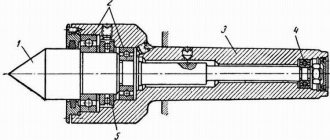
The figure above shows the design of the center intended for fixing the tailstock quill of a lathe into the conical groove. The working part or center (1) rotates thanks to ball bearings (2) and (4); in other design options, needle bearings are used. The axial pressure arising during operation is compensated by the thrust ball bearing (5). Fastening in the quill is provided by a conical shank (3). To accurately determine axial forces, some designs have a built-in device.
More reliable fixation of workpieces, especially when working with heavy parts at high speeds, is ensured by centers built into the quill. This design, shown in the figure below, provides higher fixation rigidity, which is optimal when preparing large-section chips.
There is a specially bored hole in the front part of the quill (1). It contains bearings for the sleeve (4) - thrust (3) located in the front part to absorb axial load and radial (2). A conical hole is machined in the bushing for the center (5). This design can be used to attach a drill or any other axial tool, for which the sleeve is connected with a stopper to the quill.
Device
The headstock is attached to the bed, as well as all the main parts of the machine and the tailstock. The main elements in all machines have an identical structure and a general operating principle.
Design elements:
- the fundamental framework where the controls and everything else are placed;
- quill – fastening component;
- one-piece metal body; a control lever that allows you to directly secure the quill and the base of the entire tailstock;
- a flywheel responsible for moving the quill;
- a screw with which the element is clearly secured in relation to the rest of the lathe and all its parts.
Since all the components are identical, the operating principle is not too different.
Principle of operation
The central part of the tailstock is attached to the caliper. Through it, the headstock receives translational motion, since it is equipped with an independent gear drive.
Some types of equipment produce rotational motion. The center of the tailstock itself does not rotate. The specific drive method depends on the modification of the machine, as well as on the tasks that need to be solved.
Node purpose
The main function is to securely secure the workpiece. The unit also supports the second edge of the workpiece and controls stable rotation.
When carrying out the drilling process, the tailstock is connected to the caliper, and a drill of the required size is inserted into the quill chuck.
Scope of application and features
Rotating centers are used in lathes for turning parts at rotation speeds of more than 75 m/min. At this speed, the process of increased wear of the center cone and the center hole of the workpiece begins. A partial way to solve the problem is to use lubricant and carbide tips, but the best option is to use a rotating center.
Main advantages of the equipment:
- Versatility. When using centers with replaceable attachments, parts with different conical axial holes can be processed.
- High load-bearing characteristics, significantly exceeding those of thrust clamps.
- Long service life due to reduced wear.
- Ability to work under high loads.
The main disadvantage is the presence of radial runout. This problem can be solved by using equipment with an acceptable runout indicator, or finishing at low speeds using a fixed center.
Repair and restoration of the tailstock of a lathe
When repairing the tailstock, the accuracy of the mating surfaces of the bridge with the frame and the body, the accuracy of the body opening and the height of the centers of the front and rear stock are restored, the quill, feed screw and other parts are repaired or remanufactured.
The most labor-intensive operations are to restore the accuracy of the hole in the body for the quill and restore the height of the centers.
The hole for the quill in the body is repaired by lapping, boring, followed by finishing, and using acrylic plastics.
Laps usually repair lightly worn holes. In this case, the height of the centers is restored by placing compensation pads on the guides and a new quill is made.
When repairing by boring, the height of the centers is simultaneously restored. After boring, the hole is usually finished with laps, and the quill is made of a larger diameter.
Acrylic plastics restore both the precision of the quill fit and the height of the centers. In this case, the quill is not manufactured, but repaired.
This repair method is the most effective, since it requires 3-5 times less time and money than the first two methods.
The two options for repairing the tailstock discussed below clearly confirm the profitability of repairs using acrylic plastics, in particular styracrylic of the TSh brand.
Repair of the tailstock housing and bridge without the use of acrylic plastic
The repair sequence is as follows:
- The surface of the 9th body is scraped (Fig. 60). The number of paint prints must be at least 10 on an area of 25 X 25 mm
- The surface 10 of the bridge 8 is milled and the cover is installed with glue or screws. If the bridge protrusion is tightly coupled with the housing groove, this operation is not performed
- The surfaces of the bridge mating with the hull are scraped (along the hull). The number of spots when checking for paint is at least 10 on an area of 25 X 25 mm. The protrusion of the bridge must fit tightly into the groove of the housing (without play)
- The surfaces of the bridge are scraped along the frame guides. The number of paint prints is 10-15 on an area of 25 X 25 mm. At the same time, when scraping, the surface mating with the body is ensured to be horizontal with an accuracy of 0.05 mm per 1000 mm of length. The check is carried out using a level installed on surface 9 along and across the frame guides. The frame is installed and leveled, while the plane for attaching the feed box must be positioned strictly vertically.
- Attach the bridge to the hull
- The bead rod is secured in the spindle of the machine headstock. The axis of the bead rod at the point where the cutter is attached must be 0.05 mm higher than the normal position of the spindle axis, for which: the measuring rod of the indicator, mounted on the machine support, is brought to the upper generatrix of the bead rod (at the point where the cutter is attached) and this position is fixed; loosen the front bolts securing the headstock (the spindle axis is already aligned parallel to the frame guides), use a lever to slightly raise the front part, place 0.02-0.05 mm thick foil under the front ends of the guides and secure the headstock to the bed; bring the indicator to the upper generatrix of the bead rod and notice its new position, in which the axis of the bead rod should be located 0.05 mm above the spindle axis.
- Install the tailstock in front of the caliper carriage and apply a weight for rigidity
- Boring the hole for the quill in the tailstock body (in 2-3 passes), spindle rotation speed 250 rpm; feed 0.1 mm/min. In this case, the surface finish must be no lower than V5, taper - no more than 0.02 mm, ovality - no more than 0.01 mm.
- Grind the hole in the body using an expanding mandrel mounted in the spindle and sandpaper. Spindle rotation speed 500-800 rpm, feed 10-15 m/min. Surface finish V7, taper - no more than 0.02 mm, ovality - no more than 0.01 mm
- The hole in the body is fine-tuned using a cast iron lap. Spindle rotation speed 200-300 rpm, feed - 5-8 m/min. In this case, a surface cleanliness of V 8 is achieved, the taper should be no more than 0.01 mm, and the ovality should be no more than 0.005 mm.
- Remove the foil from under the headstock guides and secure the headstock to the bed. The tailstock is assembled with a newly manufactured and fitted quill. The movement of the quill should be smooth, without backlash. The clamp should ensure reliable fastening of the quill.
- Check the position of the quill in relation to the bed guides and the coincidence of the centers of the front and rear stock, in accordance with the technical specifications in accordance with GOST 42-56.
The considered tailstock technological process is widely used in many factories, despite its significant labor intensity.
Restoring the tailstock with acrylic plastic
Restoring the tailstock with acrylic plastic is very simple and effective, since operations on precise boring and finishing of the housing hole are eliminated and it is possible to preserve the old quill. Bridge repairs are carried out in the same way as for repairs without acrylic plastic.
The technological process of restoring the hole in the tailstock housing includes the following operations:
- The hole for the quill in the body 4 of the tailstock (Fig. 60) is bored on a boring or lathe, and a layer of metal equal to 2-3 mm is removed. The cleanliness of the processing must correspond to V 1, taper and ovality are allowed no more than 0.5 mm.
- In the spindle 2 of the headstock 1 of the machine, the axis of which is adjusted to be parallel to the bed guides, a hollow mandrel with a plug 7 is installed. The outer diameter of the cylindrical part of the mandrel corresponds to the outer diameter of the repaired quill and has a size 0.01 mm larger than the quill. The mandrel is installed eccentrically relative to the spindle axis by 0.07-0.08 mm. To do this, a gasket shaped like a truncated cone with a thickness of 0.07–0.08 mm is placed in the conical hole of the spindle before installing the mandrel. The material for the gasket is paper or foil. The shape of the gasket (truncated cone) ensures uniform runout at both ends of the mandrel.
- By rotating spindle 2, check the runout of the mandrel, which should be no more than 0.15-0.18 mm, and install the spindle so that the generatrix of the mandrel with the largest positive deviation is located above the spindle axis. This arrangement of the mandrel ensures that the difference in height between the centers of the headstock and tailstock (0.05-0.07 mm) is established in accordance with the requirements of the technical specifications.
- In the body of the tailstock 4, three holes with a diameter of 6-8 mm are drilled above the hole for the quill; holes are located in the middle and along the edges of the body
- Degrease the bore of the housing and dry for 15-20 minutes until the solvent has completely evaporated.
- A thin, even layer of soap is applied to the mandrel, the tailstock body is installed and bolted to the frame.
- The hole for the quill (the space between the mandrel and the headstock body) is sealed with rings and plasticine 6; The holes of the quill fastening devices are also sealed, and three funnels 3 and 5 are installed from plasticine above the three drilled holes.
- Prepare an acrylic solution and pour it into the middle funnel. Filling is completed when the mass of styracrylic partially fills the outer funnels
- The flooded tailstock is kept in place for at least 2 hours at a temperature of 18-20 ° C
- They move the tailstock, protect the body from plasticine and tides of plastic, make lubrication grooves, drill holes, chisel the keyway and assemble the tailstock
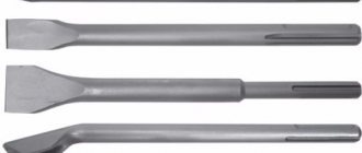
Types of rotating centers
Depending on the shape of the fixing part, two types of rotating centers are available:
- with a working cone for fastening workpieces with center holes;
- with mushroom-shaped attachment for workpieces with an internal hole - pipes, hollow shafts, etc.
By design, the equipment is divided into:
- Center with permanent roller (type A)
- Center with replaceable nozzle (type B)
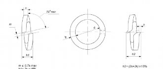
The cone of the center roller is machined at 60° (version 1) or may have an additional groove for a 30° cone (version 2).
Symbol of equipment: Center A-1-4-NP GOST 8742-75
Type A, version 1 with Morse taper 4 of increased accuracy and normal series.
Table of basic equipment parameters
| Rotating machine centers GOST 8742-75 Type A - with permanent center roller Type B - with an attachment on the center roller | ||||||||||
| Center rotating type-version-Morse taper-series | d | D | L 1 row L 2 row | L 1 row L 2 row | D1 | l1 | ||||
| Rotating center A-1-2-N | Rotating center A-2-2-N | Rotating center B-2-N | 22 | 56 | 160 | 90 | 56 | 24 | ||
| Rotating center A-1-3-N | Rotating center A-2-3-N | Rotating center B-3-N | 25 | 63 | 180 | 185 | 94 | 99 | 63 | 26 |
| Rotating center A-1-4-N | Rotating center A-2-4-N | Rotating center B-4-N | 28 | 71 | 210 | 225 | 101 | 116 | 71 | 30 |
| Rotating center A-1-5-N | Rotating center A-2-5-N | Rotating center B-5-N | 32 | 80 | 240 | 260 | 104 | 124 | 80 | 34 |
| Rotating center A-1-4-U | Rotating center A-2-4-U | Rotating center B-4-U | 36 | 75 | 220 | 235 | 111 | 126 | 75 | 36 |
| Rotating center A-1-5-U | Rotating center A-2-5-U | Rotating center B-5-U | 40 | 90 | 250 | 275 | 114 | 139 | 90 | 45 |
| Rotating center A-1-6-U | Rotating center A-2-6-U | Rotating center B-6-U | 56 | 125 | 340 | 360 | 150 | 170 | 125 | 56 |
Features of operation
Here are the basic rules for operating rotating centers necessary for precision machining of parts:
- When choosing the accuracy class of the equipment, it is necessary to leave a margin to cover runout errors due to other reasons - wear of bearings, low rigidity, etc.
- Correct installation of the part is important. The axis of the cone must coincide with the axis of rotation of the workpiece with high accuracy.
- To check the accuracy of the installation, you can place a white sheet of paper under the rotating center and evaluate the alignment. More precise control is carried out using indicators.
- If there is runout, the cone is ground in place and checked using a template. Processing is carried out with a power tool located in the tool holder.
- The beating of the rotating centers leads to the beating of the resulting part relative to the axis. When installing this part on another machine that has a different runout, a deviation from alignment may occur. To eliminate deviations, processing is carried out using a fixed center.