Common abbreviations and abbreviations are not popular terms. This can also be said about GOST - not my favorite word. Unless among the readers there is a welder who aspires to receive the status of a professional. In this case, even with all his dislike for officialdom, he should, at a minimum, treat the abbreviation GOST with respect.
Frankly, this is not enough. You need to not only respect, but also have a good understanding of the intricacies of state standards that relate to the welding industry. What is the reason for this statement? With the fact that if you have to weld metals outside your dacha, but, say, in production, then you are almost guaranteed to have to deal with working drawings. And without knowledge of the specific topology it will be impossible to read them.
Without knowledge of the specifications and symbols, these documents will be no easier to understand than the writings of the Mayan tribes. After all, modern welding technologies include many different methods that differ in technical nuances and requirements. All of them are reflected in the state standard.
The designations on technological drawings may seem intimidating at first glance. However, if you carefully study the three main GOST standards for welding technologies, then all the designations will turn into a clear and important source of information. Correct reading and understanding of the drawing greatly simplifies the task at hand.
How to Read Welding Symbols on Drawings
To do this, let's take a specific example - how it looks in this drawing.
The untrained eye sees here an incomprehensible set of letters, numbers and other mysterious signs. Prepared - a clear and understandable algorithm that simplifies working with the drawing.
Let's look at each element separately:
- o - the circle in our case means that the step along a closed line is circular. In general, they indicate here whether this is a closed line or an installation connection. In the last option it is a checkbox.
A one-way arrow indicates the seam line. It is also a shelf, with control devices placed on it - as in our version. If the seam is on the wrong side, then all the designations are written under the shelf.
- GOST 14771-76 - here they indicate which standard was used when using symbols;
- T3 - we have a T-joint (denoted by the letter T). At this point, write the type of connection and its design elements (alphanumeric combination). In the example above, there is a double-sided T-type fillet weld without beveled edges.
There are also connections or seams:
- butt C - adjacent ends are connected
- overlap (H) - the welding surfaces are shifted and one overlaps slightly the other
- angular (U) - the ends of the workpieces are welded at a specific angle
- special (O) - methods not provided for by GOSTs.
- UP - welding method. We use carbon dioxide arc welding.
Welding options also include:
- automatic submerged (A) - no cushions or linings
- previous version with pillow (AF)
- in an inert gas with a tungsten electrode without additives (IN)
- previous version with additive (INp)
- in an inert gas with an electrode that melts (IP)
- the previous version is only in carbon dioxide (CD).
- ◺6 - description of the type and dimensions of structural elements. In our example it is said that the size of the joint leg is 6 mm. Connection options also include the following: one- and two-way (SS and BS, respectively), visible and invisible (solid and dotted lines, respectively). Sometimes non-standard seams are used - in the standard you will not find information about their design dimensions.
- 50 - the number determines the length of the continuous section;
- Z - space is reserved for the characteristics of the connection. We have it in a checkerboard pattern;
- 100 - the number describes the connection or its components. In our case, a step with a value of 100 mm.
The last icon in the form of an underlined circle means that the joint surfaces need to be aligned.
At the end of the list of symbols there may be the following signs:
Types of seams according to GOST standards (squares 2 and 3 examples)
Possible methods of connecting two elements are closely discussed in GOSTs 14771-76 and 5264-80. There are the following types of welding joints:
- C – butt weld . The two elements being connected are in the same plane and at the same level. They are connected to each other by adjacent ends. This is one of the most popular connection options. Its peculiarity lies in the fact that the mechanical characteristics of the weld are very high, and the appearance of the finished structure is aesthetic. Along with the positive aspects, there are also negative ones. This type of connection remains technically difficult. It can only be performed qualitatively by experienced specialists.
- T – tee seam . This implies a connection of two elements located at an angle of 90 degrees relative to each other, and the junction has a T-shaped configuration. This is the most rigid connection option of all those considered. Therefore, it is not used in cases where some elasticity is important for the finished structure.
- N – lap seam . Two workpieces are located parallel, but not in the same plane. They are in contact with some overlap of the plane. A fairly strong and reliable connection method, but in terms of rigidity it is inferior to the T-type version.
- U – fillet weld . The ends of two workpieces are positioned at an angle of 90 degrees. The ends melt, resulting in a fairly strong and rigid connection.
- O – special types . This designates all other options for welding workpieces that are not described in the standard.
Both GOST standards mentioned at the beginning of the section have common features and overlap with each other. For manual arc connection according to GOST 5264-80:
- C1 – C40 butt;
- U1 – U10 corner;
- H1 – H2 overlap;
- T1 – T9 tee.
Performing welding work in an inert environment in accordance with GOST 14771-76:
- U1 – U10 corner;
- C1 – C27 butt;
- H1 – H4 overlap;
- T1 – T10 tee.
The example above contains the numbers just discussed. The second square contains information on the standard used - 14771-76. The third square describes the connection method - double-sided T-joint without beveled edges.
Image of welding seams
You can designate welds in the drawing using two types of lines: solid and dashed (dotted). The first is used if the joints are external and visible, the second - if the joints are not visible.
A mandatory element is an extension arrow: it indicates where the seam is located. The placement of the symbol depends on whether the joint is visible or not. For visible seams - above the arrow, for invisible - below the arrow.
The seam can be multi-pass. This occurs when the joint is made by several passes that overlap one another.
As for the connection joints, they are:
- single-sided (SS) - when parts are welded on one side of the surface;
- double-sided (BS) - when the heating medium moves in turn from the lower surface to the upper. The root of the butt weld in this case is located inside the section.
It is important to trim the edges. This will give the required depth when welding using the fusion method. Welding technology and material thickness determine all edge parameters.
See what the edge sections might be like.
Welding connections are:
- point;
- solid;
- intermittent.
The specific option depends on the nature of the execution.
An intermittent weld may be designated:
- solid line if the joints are visible;
- dashed line if the joints are invisible.
Spot welding is indicated in the drawing by a + sign consisting of solid lines and the selected welding option is not important.
Examples of designation of welds.
Example 1.
| Seam cross-sectional shape | a) the arrow points to the front side of the seam | b) the arrow points to the reverse side of the seam |
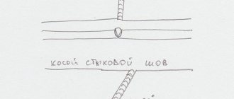
A butt joint seam with a curved bevel of one edge, performed on both sides by manual arc welding (C13 according to GOST 5264 - 80) during installation of the product (). Reinforcement has been removed on both sides (). Roughness parameter of the weld surface: on the front side – Rz 20 µm; on the reverse side - Rz 80 µm.
Example 2.
| Seam cross-sectional shape | a) the arrow points to the front side of the seam | b) the arrow points to the reverse side of the seam |
Corner joint weld without beveled edges, double-sided (U2 according to GOST 11533–75) performed by automatic submerged arc welding (A according to GOST 11533–75) along a closed line.
Example 3.
| Seam cross-sectional shape | a) the arrow points to the front side of the seam | b) the arrow points to the reverse side of the seam |
A butt joint seam without beveled edges, one-sided, on the remaining backing (C3 according to GOST 16310–80), performed by welding with heated gas with an additive (G according to GOST 16310–80).
Example 4.
T-joint seam without beveled edges, double-sided intermittent with a staggered arrangement (T3 in accordance with GOST 14806-80) performed by manual arc welding in shielding gases with a non-consumable metal electrode (RINp in accordance with GOST 14806-80). The weld leg is 6 mm (Δ6), the length of the welded area is 50 mm, the pitch is 100 mm (Z).
t w - length of the welded section of the seam t pr - length of the step section of the intermittent seam
Example 5.
An overlap weld without beveled edges, one-sided (H1 in accordance with GOST 14806-80), performed by gas-shielded arc welding with a consumable electrode (PIP in accordance with GOST 14806-80). Seam along an open line (). Seam leg 5 mm (?5).
How are joints designated by type of execution?
You can see all designation options in the tables below.
Butt joints
| The nature of the joints | No bevels | Bevel on one edge | Bevel on two edges | Two symmetrical bevels on both edges |
| Unilateral | ||||
| Bilateral | ||||
| One-way connections using a gasket |
Fillet type welds
| Character of the seam | No bevel |
| Unilateral | |
| Double sided | |
| End-to-end one-sided | |
| End-to-end double-sided |
T-type welds
| Nature of the connection | Without bevel |
| Double-sided regular | |
| Double-sided staggered |
Overlapping joints
| Butt joint | Without bevel |
| Double-sided joint | |
| Intermittent continuous seam |
Welding methods (square 4)
The standardization requirements also describe welding methods. The most common of them are:
- A – automatic. It is carried out using flux, but without gaskets and pillows;
- AF is also automatic. But in this case, on the pillow;
- IN – performed in an inert environment using a tungsten electrode without additives;
- INp is the same method as the previous one with the only difference being that additives are used;
- IP – metal connection is carried out in an inert environment using a consumable electrode;
- UP is the same as IP, only carbon dioxide is used instead of an inert medium.
In this case, the fourth square contains the UP symbols. This means that welding was performed in a carbon dioxide environment with consumable electrodes.
Seam options depending on the outer surface
What the mechanical and physical characteristics of the connecting joint will be depends on its shape. If the joints have convexities, then they are processed with a milling cutter or abrasive wheels.
In the table I show what convex joints are and how the welded joint is indicated in the drawing.
| Connection types | Joint | How is it portrayed? | Characteristics |
| Normal | _________ | Economical in the process of creation, stable under constant loads. | |
| Concave | Best used under dynamic loads, easy to perform. | ||
| Convex | They involve the use of consumables and are not economical. |
Types of seams and their interpretation
GOST standards for manual arc welding and gas welding distinguish different types of welds and their interpretation. Types of welded joints are designated by letters for easier recording and saving space. There are a butt seam (denoted by the letter “C”), an end seam (also the letter “C”), an overlap (“H”), a T-weld (“T”) and a corner seam (“U”). Let's take a closer look at each type of connection.
A butt welded joint is made at adjacent ends, and the parts to be welded are in the same plane. This type of weld is the strongest and most durable; it is widely used when welding particularly critical metal structures. Before welding, it is necessary to carefully prepare the metal surface and make sure that all parts will be welded in accordance with the drawing.
The end seam, as the name suggests, is formed along the ends of the parts. The side surfaces of the parts are securely connected to each other. The end weld is often used when welding thin metals.
The overlap seam is less demanding on the quality of work than the previous ones. But at the same time, it does not have such good strength characteristics and tolerates loads less well. To make an overlap seam, place the parts parallel, but with a slight offset to the side and partially overlapping each other.
The T-welded connection is one of the toughest and most durable, but does not withstand bending loads well. To make a T-seam, place one part horizontally, the second vertically and weld with the first end facing the surface.
The fillet weld is not used as often as other types of joints. This seam is relatively reliable and durable. One part relative to another can be turned end-to-end and positioned at different angles, depending on the drawing.
All welded joints, regardless of their type, can be single-sided (or as they are called “SS”; this abbreviation is used in drawings around the world) or double-sided (abbreviated “BS”). Single-sided seams are obtained by welding on one side of the part, and double-sided seams are obtained by welding on both sides.
If you need to fusion weld parts, you will need to cut the edges. There are many forms of edge separation; they are characterized by different angles, gap sizes, and so on. The choice of cutting shape depends on the thickness of the metal and the welding method. We have provided some examples of the edge section in the image. You can use any one like in the picture below.
EXAMPLES OF ALPHANUMERIC SEAM DESIGNATIONS
| GOST | Name of GOST | Connection type | Alphanumeric designation of seams |
| 5264-80 | Manual arc welding. Welded connections | Butt Corner Tee Lap | C1 - C40 U1 -U10 T1 - T9 H1 -H2 |
| 14771-76 | Gas shielded arc welding. Welded connections | Butt Corner Tee Lap | C1 - C27 U1 -U10 T1 -T9 H1 -H4 |
Welding drawing: auxiliary signs
In addition to arrows and letters, auxiliary symbols can be added to the welding drawing to indicate welds.
Below you can see the standard structure of the symbol, its “skeleton”, on which “muscles” should then appear in the form of letters or other signs.
Auxiliary symbols on welding drawings include alphanumeric combinations that contain information about the type of seam and type of connection.
This sounds pretty confusing, but here's a quick example: We have the designation C1 and it stands for "single-sided butt weld." C is a letter indicating the type of seam, and 1 is a number indicating the side of welding. Double-sided welding is indicated by the number 2.
Below you can see symbols of seams and joints for some welding methods.
Welding methods also have their own symbol. They are also marked with a letter.
The symbol is indicated in regulatory documents. Based on the standards, the welding process indicated on the assembly drawing is carried out.
Below you can see the main welding methods and their designations:
- Automatic submerged arc welding, without the use of flux pads and pads during operation (indicated by the letter “A”).
- Automatic submerged arc welding using a flux pad (“AF”).
- Gas shielded welding using tungsten rods and no wire (“IN”).
- Welding in a shielding gas environment using tungsten rods and using wire (INp).
- Gas shielded welding using consumable rods (“IP”).
- Welding with consumable rods in a carbon dioxide environment (“WW”).
Detachable connections, their classification and purpose
Classification and purpose of detachable connections
Detachable connections include: threaded connections, connections using pins, wedges and keys, as well as toothed (spline) connections and others.
The detachable connection allows for repeated disassembly and subsequent reassembly; in this case, the integrity of the parts included in the connection is not compromised.
Threaded connections
Threaded connections are connections in which one of the parts has an external thread and the other has an internal thread. This connection is obtained by screwing one part onto another.
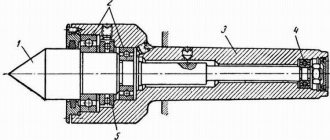
Bolted connection
It consists of a bolt, nut and washer and fastened parts. In parts 1 and 2, a hole is drilled with a diameter larger than the diameter of the bolt thread ( ). Insert bolt 3 into the hole, put on washer 5 and screw on nut 4 (Figure 17.1).
Features when performing a bolted connection:
- In the connection drawing, only three dimensions are indicated: thread diameter, bolt length and hole diameter in the parts being fastened;
- The bolt head and nut in the main image are usually shown with three faces;
Hairpin connection
A stud connection consists of a stud, nut, washer and fastened parts (Figure 17.2).
A socket is drilled into part 1 and a thread is cut into it. The threaded end of the pin 3 is screwed into the socket. A hole with a diameter of 1.1 d is drilled in part 2 and put on a pin. Then put washer 5 on the stud and screw on nut 4.
Features of making a hairpin connection:
- The dividing line of the fastened parts must coincide with the thread run-out of the screwed-in threaded end of the stud;
- The pin socket ends in a cone at an angle of 120°. This cone is of a technological nature and is obtained from a drill;
Screw connection
A screw connection consists of a screw and fastened parts (Figure 17.3).
In part 1, a socket is drilled into which a thread is cut. A hole with a diameter of 1.1 d is drilled in the attached part 2. The screw fits freely into the hole in part 2 and is screwed into part 1.
The conical head of the screw, called countersunk, should not protrude above the surface of the part.
The slot in the head for the screwdriver is positioned in the front and left views perpendicular to the front and profile planes of projection, and in the top view - conventionally at an angle of 45 degrees.
If the diameter of the screw head in the drawing is less than 12 mm, then the slot is shown as one thick line.
Constructive, simplified and conventional images of threaded connections
There are constructive, simplified and conventional images of fasteners and their connections.
When constructing a design, the dimensions of the parts are selected and drawn according to the relevant standards.
In a simplified representation, the dimensions of fasteners are determined by conditional relationships depending on the thread diameter.
A conventional image is used when the diameter of the rod is less than 2 mm.
In simplified illustrations, threads are shown along the entire length of the threaded fastener shank. Chamfers, roundings, and gaps between the part rod and the hole are not shown. In views obtained by projection onto a plane perpendicular to the thread axis, the thread on the rod is depicted by one circle corresponding to the internal diameter of the thread (the arc corresponding to the internal diameter of the thread is not depicted). These same views do not show the washers used in the connection. In simplified images, the end of the part hole is not shown (Figure 17.4).
Wedge connection
A wedge connection is used when it is necessary to quickly disassemble and assemble machine parts to be connected, as well as tightening parts with adjusting the corresponding gaps between them (Figure 17.5).
A wedge is a block that has a bevel on one side with a certain slope. The wedge is rounded along the edges and ends.
Connection using pins
According to their shape, pins are divided into cylindrical and conical. Pins are used for mutual installation of parts, as well as connecting and safety parts.
Keyed connection
Keys are used for detachable connection of parts when transmitting torque and axial force. A keyed connection consists of a wheel, a shaft and a key. A key is inserted into a special groove made on the shaft and the wheel is placed on the shaft so that the groove of the wheel hub hits the protruding part of the key.
The dimensions of the key design are standardized and depend on the diameter of the shaft. There should be a small gap between the upper non-working edge of the key and the edge of the hub groove. According to their design, keys are divided into prismatic (Figure 17.7, version 1), segmental (Figure 17.8) and wedge (Figure 17.9).
Designation examples:
- parallel key - Key GOST 23360-78, where 2 is the design (one end is rounded, the other is straight); 12×8 - section; 45 - key length;
- taper key - Key GOST 24068-80 (version 1 is not specified);
- segment key - Key GOST 24071-80, where 10 is the width; 16 - height of the key (version 1 is not specified).
Spline connections
A toothed, or splined, connection of a part with a shaft is formed by protrusions on the shaft and depressions of the same profile in the bushing or hub. (A spline connection can be considered a “multi-key” connection, in which the keys are integral with the shaft and located parallel to its axis). Compared to a keyed connection, it is capable of transmitting greater torques, and it is easy to carry out overall centering of the sleeve and shaft and their axial movement.
It is used in critical mechanical engineering structures.
There are standard splines with straight-sided and involute profiles in cross section. Triangular profile splines are not standardized. The slots in the longitudinal section are not conventionally hatched. A cross-section (section) is allowed to show the profile of one tooth and two cavities. The rest are indicated by circles: the tops of the teeth are a solid main line, and the valleys are a solid thin line. The image of a spline connection (Figure 17.11) with straight-sided splines differs from the image of a connection with involute splines (Figure 17.12) in that the latter has a dividing surface line (dash-dotted line).
The main convention in depicting spline joints is that the longitudinal section shows only that part of the bushing splines that is not covered by the shaft splines.
The symbol for straight-sided splines includes: the designation of the centering surface (letters D, d or b), the number of splines z, the diameter of the recesses d, the diameter of the projections D, the width of the spline b. In addition, the designations of the tolerance fields must be indicated.
Figure 17.13 shows an example of a designation in a connection, Figure 17.14 - on a shaft, Figure 17.15 - in a hole.
Centering surface D, z=8; d = 36mm, D = 40mm, b = 7mm.
Permanent connections
Permanent connections include: riveted, welded, obtained by soldering, gluing, by pressing parts with tension.
Riveted connections
Riveted joints are used in connecting parts made of metals, which are generally difficult to weld, when connecting metal products with non-metal products (Figure 18.1). These connections are used in structures operating under the influence of shock and vibration loads.
A rivet is a round rod with a head at one end; the shape of the head varies.
Solder connection
When connecting by soldering, in contrast to welding, the soldering point is heated only to the melting temperature of the solder, which is much lower than the melting temperature of the material of the parts being connected. The connection of parts is achieved by filling the gap between them with molten solder. Soldering seams are conventionally depicted according to GOST 2.313-82 with a line twice as thick as the solid main line and are indicated by a symbol that is applied on a leader line from the solid main line.
A seam made along a closed line (along the perimeter) is indicated by a leader line ending in a circle with a diameter of 3...5 mm (Figure 18.2).
Bonding by gluing
The seam obtained during gluing is depicted in the same way as the seam during soldering, only a different icon is placed in the designation (Figure 18.3).