When assembling structures and metal components, threaded connections and rivets are used. Sometimes you need to hide the head of a bolt, screw, or other type of connection. In these cases, the so-called secret is used. That is, at the beginning of the connecting hole, a small depression is made in the metal, where the head is hidden. You can make such a countersink using countersinking - this is a certain type of processing of the beginning of a hole, when it is expanded in diameter and deepened to a certain height. The shape of the recess may vary.
Countersinking should not be confused with countersinking - these are different operations that are performed with different tools. But the equipment that drives such cutters may be the same.
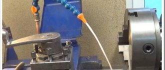
Countersinking can be done using a hand-held electric drill. The difference from the factory version here will be a low level of processing accuracy, but it is quite possible to obtain a countersink at home.
The essence of the countersinking process
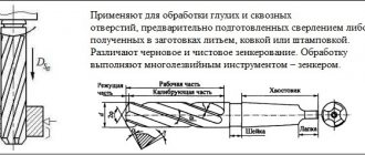
Countersinking and drilling are closely related. Typically, countersinking is carried out along a finished hole, but there are cases when it is necessary to make a recess without pre-drilling. In both versions, a countersink tool of different designs is used.
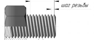
The countersinking process itself is very simple: a special cutter is used to chamfer the hole. The more metal removed, the larger the depression. The countersink shape is usually conical. The main thing here is to maintain strict alignment of the cutting element and the hole: there must be perfect alignment. Otherwise, there will be a displacement of the recess relative to the hole, and the screw head will not be able to fit into it.
To perform a countersinking operation to obtain chamfers and recesses, it is necessary to go through the following process steps:
- Measure the head of the threaded hardware for which the recess will be made (this means both the diameter, height, and bevel angle if the head has a countersunk design).
- Select the appropriate countersink and secure it in the drilling or turning equipment.
- Strictly observing the relationship of the axes, fasten the workpiece with the hole opposite the cutter.
- Turn on the drilling equipment and set the required number of revolutions (if the circuitry of the machine allows it) or deliberately select the necessary tool for the equipment parameters.
- Countersink the hole.
Main types of countersinks
Now let's look at species diversity. We have already clarified that the procedure may vary depending on the required task. Now we will analyze these points in more detail. Look at existing classifications.
Cylindrical
An operation of this type is often used in almost any type of production. The result is a cylindrical recess. It is an ideal choice for screws and bolts. And these fasteners in standard format are common in almost all designs. In fact, this is the most popular and current type of countersinking holes in metal.
Conical
The result is a cone-shaped depression. It is used not only for closing caps, but also for chamfering and preparing the surface for further work. Sometimes this method is used to simply remove metal hair from sharp edges. That is, they are cleaning. And here, the difference between the procedures becomes minimal. After all, countersinking and countersinking a recess are both methods of cleaning and grinding. True, in the first case, the alignment of a strict geometric shape is also added.
For production activities, a conical-shaped tool is used. The angle is selected for a specific task. But usually used at 90 or 120 degrees.
Flat and end
This method is sometimes called countersinking. A special final type of operation. Used in ready-made recesses. So that the caps themselves and other hardware for concealment fit tightly and without gaps. To do this, the surface is cleaned. And this is where we need these varieties.
In fact, counterbore and countersink are a small difference. It’s just that this is a narrower activity, which has this name only for flat or end stripping.
Purpose and features of countersinking
The main area of application of countersinking is in technological processes in the manufacture of machine tools, mechanisms and the assembly of metal structures. Using this operation, the following tasks are achieved:
- In pre-fabricated holes, recesses in the shape of a cylinder or cone are obtained.
- Planes of reference value are formed in the area of the holes.
- Countering the holes allows you to obtain channels with a chamfer removed in them.
- Forming recesses to hide threaded fastener elements.
Countersinking holes has its own characteristics; they are determined by the type of metal that is being processed, the design of the cutter and the final task of the operation:
- If cast iron parts or metals based on hard alloys are being processed, then a special emulsion should be supplied to the work area for cooling.
- The operating speed of the motor shaft must correspond to the operating speed of the countersink. For tools made of high-speed steel, the speed is always lower than for tools with carbide tips.
- To select a countersunk screw head, use a conical cutter with the angle of the end knives equal to the angle of the head cone.
Countersinking is done at the very last stage after countersinking and reaming.
Differences between countersinking and countersinking
Countersinking and countersinking are completely different hole processing operations.
The countersinking process involves the impact on the entire drilled channel. And the purpose of countersinking is to level this hole, to make it better in terms of all geometric parameters and the cleanliness of the channel surface. For countersinking, a special tool (countersink) has been developed, the main knives of which are arranged in a spiral along the entire body of the tool (the length of the body, as a rule, exceeds the length of the hole channel). The countersink only works on part of the hole at the beginning. Its main task is to make a countersunk or chamfer. Therefore, the tool mainly has knives at the end. The only thing that a countersink and a countersink have in common is that they are driven using the same machines.
Countersinking
To obtain a groove or hole in a metal surface, first of all we need to drill it. This is always the initial stage. But before the development stage, the resulting recess must also be cleaned. That is, remove all kinds of metal layers, burrs, and irregularities. And adjust the accuracy to the parameter indicated in the drawings. It is this stage of processing, almost finishing, that we need.
For this, a special tool is used - a countersink. With it we can achieve:
- Accuracy class adjustments up to level 4, and in some cases even level 5.
- Increasing the level of adhesion of the coating, giving it a uniform and rough surface, which is important for subsequent adhesion.
- Working with geometry. That is, the ability to give an object a conceived geometric shape with symmetrical edges.
Let's return to the tool with which the entire technical process is carried out. Despite the external similarity, the differences between a countersink and a drill are very serious. And precise, more cutting edges and larger jumpers between them. As a result, we get from 3 to 4 edges. And together they exert smooth pressure on the metal and reliably adhere to the surface. And what is equally important, they do not remove the chips longitudinally, but only transversely. The result is a kind of intensive grinding.
The species diversity of this instrument is quite extensive. The main aspect is the number of cutting edges. 3 and 4 are often used. But there are also specialized tools used in special production areas. Where there is a need for high-precision processing. Such devices have up to 8 edges. Also, classification often affects the type of rod. It can be removable, which is usually necessary when working with large hole diameters. Up to 20 mm. And if the production concerns small grooves, around 8-12 mm, then it is better to use a one-piece device. There is also a plug-in option, which should be called an intermediate link between the designated types.
Equipment and tools
The main tool used for countersinking is called a countersink. This is a type of cutter consisting of a working part and a shank. The working part has several cutting edges; the tool is attached to the shank in the equipment chuck. There are conical and cylindrical cutters. The raw material for the manufacture of countersinks is carbon or alloy tool steel.
Conical countersinks are characterized by the angle of inclination of the knife. The most commonly used elements are those with cone angles of 120, 90, 60 and 30 degrees. Cylindrical cutters have teeth at the end. These teeth can be from 8 to 4 pieces. In addition, the cylindrical tool has an element guiding the hole, which is called a pin. Thanks to this element, the cylindrical cutter is always aligned with the hole it is processing.
For countersinking holes, special holders have also been developed into which countersinks are inserted. They may have rotating or non-rotating type limiters.
VIEW Countersinking cutters on AliExpress →
The correct process for countersinking metal
Mistakes when performing a task almost always lead to one sad epilogue - marriage.
If the countersink is chosen incorrectly, the hole diameter often turns out to be larger than what was planned according to the initial drawing. And if the cutting edges have already become very sharp, then the recess, on the contrary, will be too narrow. It is important to choose the feed speed, as well as clearly define the center. Otherwise, the geometry will be broken. And even without displacement, the quality of cleaning will definitely not be satisfactory according to the threshold values. In order not to accumulate waste and not perform one task several times, you need to initially approach it responsibly.
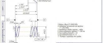
Countersink designation in the drawing
In production, countersinking of holes is carried out according to the drawing. The countersink in the drawing is displayed in uppercase and capital Latin letters and Arabic numerals. The meaning of the letters and numbers is as follows:
- d1 – indicates the main diameter of the channel;
- d2 – for countersinking diameter;
- L1 – displays the length of the cylindrical channel;
- L3 is the countersinking depth;
- L4 – indicates the depth of the chamfer;
- j is the size of the central countersinking angle;
- α (alpha) – chamfer angle size.
Dear site visitors: mechanical engineers, craftsmen and those simply familiar with the topic, support the discussion in the comments! Your professional comments are very important to us.
DESIGNATION OF SURFACE ROUGHNESS
1.1. Surface roughness is indicated in the drawing for all product surfaces made according to this drawing, regardless of the methods of their formation, except for surfaces whose roughness is not determined by the design requirements.
1.2. The structure of the surface roughness designation is shown in Fig. 1.
When a sign is used without specifying the parameter and processing method, it is depicted without a shelf.
Crap. 1
1.3. To indicate surface roughness, one of the signs shown in the drawing is used. 2.
Height h
should be approximately equal to the height of the dimensional numbers used in the drawing.
The height H
is equal to (1.5 ... 5)
h.
The thickness of the character lines should be approximately equal to half the thickness of the solid main line used in the drawing.
Crap. 2
To designate surface roughness, the processing method of which is not specified by the designer, use the sign (Fig. 2a).
To designate surface roughness, which should be formed only by removing a layer of material, a sign is used (Fig. 2 b
)
.
To designate the surface roughness, which must be formed without removing a layer of material, a sign is used (Fig. 2 in
) indicating the value of the roughness parameter.
1.2, 1.3. (Changed edition, Amendment No. 3).
1.4. The surfaces of a part made from a material of a certain profile and size, which are not subject to additional processing according to this drawing, must be marked with a sign without indicating the roughness parameter.
The condition of the surface indicated by the sign must comply with the requirements established by the relevant standard or technical specifications, or other document, and this document must be referenced, for example, by indicating the range of material in the column 3
main inscription of the drawing according to GOST 2.104-2006.
1.5. The value of the roughness parameter according to GOST 2789-73 is indicated in the roughness designation after the corresponding symbol, for example: Ra
0.4;
R
max 6.3;
Sm
0.63;
t
50 70;
S
0.032;
Rz
50.
Note. In the example t
50 70 the relative reference length of the profile
tp
= 70% is indicated at the profile cross-section level
p
= 50%,
1.5a. When indicating the largest value of the roughness parameter in the designation, the roughness parameter without maximum deviations is given, for example: .
1.5b. When specifying the smallest value of the roughness parameter, “min” should be indicated after the parameter designation, for example: ; .
1.6. When specifying a range of values for a surface roughness parameter in the roughness designation, the limits of the parameter values are given, placing them in two lines, for example:
| and so on. |
The top line gives the parameter value corresponding to a coarser roughness.
1.7. When specifying the nominal value of the surface roughness parameter in the designation, this value is given with maximum deviations in accordance with GOST 2789-73, for example:
Ra
1 + 20%;
Rz
100–10%;
Sm
0.63+20%;
t
50 70 ± 40%, etc.
1.5 - 1.7. (Changed edition, Amendment No. 2,
3 ).
1.8. When specifying two or more surface roughness parameters in the roughness designation, the parameter values are written from top to bottom in the following order (see Figure 3):
profile irregularity height parameter
profile irregularity step parameter,
relative reference length of profile
Crap. 3
(Changed edition, Amendment No. 3).
1.9. When normalizing the requirements for surface roughness by parameters Ra, Rz, Rmax
the base length is not given in the designation of roughness if it corresponds to that specified in Appendix 1 of GOST 2789-73 for the selected value of the roughness parameter.
(Changed edition, Amendment No. 2).
1.10. Symbols for the direction of irregularities must correspond to those given in the table. Symbols for the direction of irregularities are shown in the drawing if necessary.
| Types of roughness direction | Designation | Types of roughness direction | Designation |
The height of the symbol indicating the direction of irregularities should be approximately equal to h.
The thickness of the sign lines should be approximately equal to half the thickness of the solid main line.
1.11. The type of surface treatment is indicated in the roughness designation only in cases where it is the only one applicable to obtain the required surface quality (Fig. 4).
Crap. 4
1.10, 1.11. (Changed edition,
Amendment No. 3 ).
1.12. It is allowed to use a simplified designation of surface roughness with its explanation in the technical requirements of the drawing according to the example indicated in Fig. 5.
Crap. 5
In simplified notation, the sign and lowercase letters of the Russian alphabet are used in alphabetical order, without repetitions and, as a rule, without gaps.
(Changed edition, Amendment No. 2,).
1.13. If the direction of roughness measurement should differ from that provided for by GOST 2789-73, it is indicated in the drawing according to the example shown in Fig. 6.
Crap. 6
(Changed edition. Amendment No. 3).