Grinding technologies are used in the machine and machine-tool industries, jewelry, optics, and construction. They are technological operations for processing materials with abrasives. They are used for finishing surfaces of flat, cylindrical, end, internal and external parts and products made of hard materials, as well as restoration of cutting ability and configuration. The goal of the process is to obtain a surface with the required roughness and cleanliness. Grinding of parts is a type of cutting operations, with the help of which the dimensions of the part are adjusted to the required value indicated in the design drawings. To process materials for various purposes by grinding, a large number of abrasives, tools and equipment are used. The quality of work depends on the correct choice of grinding technology method and the necessary components. By grinding, accuracy classes 1 and 2 and surface cleanliness classes 6–10 are achieved.
Metal grinding
The processing of metal and various alloys using an abrasive material is usually called grinding. This technology allows you to change the roughness and other parameters of the outer or inner cylindrical, as well as flat surface. Metal grinding can be carried out using various special equipment. When considering the features of such mechanical processing, you need to pay attention to the following points:
- The grinding process is the final stage of processing, which is carried out to obtain a certain roughness.
- This technology is not used to change sizes over a large range.
- Using modern equipment, the surface can be brought to the required roughness after heat treatment of the metal.
When carrying out the operation in question, a fairly large number of features are taken into account:
- Wheel speed is a parameter that depends on the outer diameter of the abrasive and the capabilities of the machine.
- Speed of movement of the part.
- Depth of cut.
- Possibility of cross feeding.
It is worth noting that today such technology is gradually being replaced by fine turning of metal at high speeds and minimal feed.
The influence of speed on processing quality
The grinding speed is usually called the rotation speed of the grinding wheel. Measured in m/s. The productivity of the process increases with its increase. The grinding speed is selected taking into account the diameter of the wheel, the material of the workpiece and the grinding wheel, the type of grinding, and the design of the machine. Usually they try to select a circle of the largest diameter permissible for installation on a specific machine model, and select the required number of spindle revolutions from the table indicated in the passport data. High speed leads to vibration, which affects the quality of grinding and will also cause wheel wear. To avoid negative consequences resulting from overheating, in some cases special cutting fluids (coolants) are used.
In the video you can see how the gear grinding process is carried out on a CNC machine:
We ask those who have dealt with grinding to share their experience and in the comments to the text tell us about the nuances of working on machines and manually.
Main types of grinding
Grinding of parts can take place using a variety of technologies. The most widespread are the following:
- Circular grinding of metal.
- Changes in the roughness of internal surfaces.
- Gear grinding.
- Centerless technology.
- Sanding flat surfaces.
In addition, classification can be carried out according to the type of material used during processing. To automate the process and reduce labor costs, specialized machines are used. There are also models with a built-in CNC unit, which automates the process and ensures high quality of the resulting surface.
Equipment and tools used
Grinding work on metal is carried out using special machines or manually. Grinding machines are divided into groups:
- cylindrical grinding;
- internal grinding;
- roughing and grinding;
- special spline grinders;
- surface grinding machines with round or flat table;
- lapping and polishing.
Such a variety of machines makes it possible to obtain a roughness coefficient of 0.32 microns during ordinary metal grinding, and up to 0.08 microns during precision processing. With the use of special abrasive compounds, this figure reaches 0.02 microns.
The second method involves the use of hand tools. These can be electric grinders, drills or devices for manual processing (abrasive wheels, belts, blades, various files and needle files).
Cylindrical external grinding
Metal grinding when using this technology involves the use of special equipment. Among the features of cylindrical grinding, we note the following points:
- An abrasive wheel is used as a consumable. It rotates around its axis.
- Simultaneously with the circle, the workpiece rotates in the opposite direction. Due to this, the efficiency of the operation is significantly increased.
- Longitudinal and transverse feeds can be carried out, due to which the depth of penetration of the tool changes and processing is ensured along the entire length.
Principle of cylindrical grinding
Cylindrical external grinding
This technology is often used for grinding cylindrical workpieces. This is due to the fact that when the grinding wheel comes into contact with a cylindrical workpiece, the entire surface is processed at the moment of rotation.
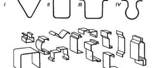
TYPES AND METHODS OF GRINDING
Grinding
To carry out grinding, it is necessary that the workpiece and the grinding wheel have certain relative
movements without which cutting is impossible. When grinding, the main cutting movement is the rotation of the tool (Fig. 13.4), and the feed movements (they can be different) are communicated to the workpiece or tool. A distinction is made between grinding with the periphery of the wheel and the end of the wheel; in the first case, the cutting part is the outer surface of the circle, the generatrix of which is parallel to the axis of its rotation, and in the second case, the end of the circle. Depending on the location and shape of the workpiece surface being processed 2, grinding is divided into the following types: external (Fig. 13.4, a, b, c), when the outer surface of the workpiece is processed; internal (Fig. 13.4, d), when the internal surface of the workpiece is processed; flat (Fig. 13.4, e, f), when a flat surface is processed; profile, when a surface is processed, the generatrix of which is a curved or broken line. Grinding a rotating surface is called cylindrical grinding, a spherical surface is called spheroid grinding, the side surfaces of gear teeth are called gear grinding, the sides and cavities of a thread profile are called thread grinding, and spline surfaces are called spline grinding. A distinction is also made between grinding in centers (if the workpiece is mounted in centers) and in a chuck (if the workpiece is mounted in a chuck). In mechanical engineering, cylindrical (external and internal) and flat grinding are most often used.
Cylindrical external grinding
External cylindrical grinding (Fig. 13.4, a) is carried out by a combination of the following movements: rotation of the grinding wheel 1 (the main cutting movement), rotation of the grinded workpiece 2 around its axis (circular feed v3), rectilinear reciprocating movement of the workpiece or grinding wheel along its axis (longitudinal feed 5pr); lateral movement of the grinding wheel onto the workpiece (or vice versa) (transverse feed S„) or feed to depth of cut). When grinding with longitudinal feed Snp, transverse feed S„ is carried out periodically (at the end of each double or single stroke of the machine table). With external circular grinding using the plunge method (Fig. 13.4, b), the height of the wheel is equal to or greater than the length of the workpiece being ground, so there is no need for longitudinal feed, and transverse feed is carried out continuously during processing. In centerless external grinding (Fig. 13.4, c), the workpiece 2 is placed on the support knife between the grinding worker 1 and the feed (leading) 4 wheels. By rotating circle 4, workpiece 2 is given rotation (v3) and feed 5pr; to obtain the latter, circle 4 is installed at a slight angle a to the axis of circle 1.
Cylindrical internal grinding
Cylindrical internal grinding is carried out by longitudinal feed of a 5pr grinding wheel (or workpiece) and plunging. For circular internal grinding with longitudinal feed (Fig. 13.4, d), the same movements are required as for external circular grinding. Internal plunge and internal centerless grinding are used; in the latter case, the workpiece is not secured. Flat grinding is carried out with the periphery (Fig. 13.4, e) and the end (Fig. 13.3, f) of the wheel. The cutting speed during grinding exceeds the cutting speed during blade processing and is 25–35 m/s (conventional grinding), 35–60 m/s (high-speed grinding) and over 60 m/s (high-speed grinding). When grinding, the cutting speed significantly exceeds the feed rate. Grinding intended to remove the defective layer from workpieces is called roughing. Grinding one or more surfaces of one or more workpieces simultaneously with several circles is called multi-circle grinding. Abrasive processing, in which the tool and the workpiece perform rotational, reciprocating, oscillating or other complex motion at speeds of the same order, is called finishing: The main types of finishing are lapping, honing, superfinishing. Abrasive processing that serves only to reduce the roughness of the surface being treated is called polishing. Grinding the working part of a blade cutting tool is called sharpening. Other types of abrasive processing include jet-abrasive, liquid-abrasive, vibro-abrasive, as well as special abrasive processing (using electrical discharge destruction of metals, their electrochemical dissolution, vibrations with ultrasonic frequency, magnetic field, etc.).
EXTERNAL CYLINDER GRINDING
This type of grinding is used to process the outer surfaces of parts such as bodies of rotation with rectilinear generatrices. Center holes or outer cylindrical surfaces are used as technological bases. Depending on the direction of the translational movement of the feed, the following grinding methods are distinguished. Plunge grinding: is ensured by the movement of the longitudinal feed snp in one direction, perpendicular to the axis of the workpiece, which is ground as it rotates. Oscillating grinding (longitudinal working strokes): the grinding wheel or workpiece, along with a rotational movement, performs a reciprocating motion designed to process surfaces of considerable length, exceeding the height of the grinding wheel. At the end of a double or each pass, the wheel is fed to the set grinding depth or cross feed amount. Shoulder grinding (a combination of plunge-cut and oscillating grinding): individual areas of the surface (ledges) of the workpiece are processed sequentially by plunging a wheel, the shoulders should overlap each other. The remainder of the allowance is then removed by oscillating grinding. Deep-feed grinding can be done with either longitudinal or transverse feed. When grinding with longitudinal feed, all (or almost all) of the allowance is removed in one pass of the wheel. The latter is ruled by a step or on a cone. When grinding with cross feed, the workpiece is subjected to slow rotation. The circle cuts into the workpiece with an increased feed to the entire (or almost the entire) amount of the allowance and during one revolution of the workpiece the entire allowance is removed. The processing scheme is similar to plunge-cut grinding with the periphery of a wheel. In multi-circle external grinding of one or more workpieces, the wheel is fed perpendicular to the axis of the workpiece or at a certain angle to it. The choice of grinding method is determined by the type of production, the design of the part, the amount of allowance and the requirements for accuracy and quality of processing.
According to the intensity of allowance removal, all external cylindrical grinding operations are divided into rough, preliminary and fine grinding. Rough grinding is used to remove a defective layer (more than 1 mm thick per diameter) from workpieces after casting and forging. stamping, rolling. Circle speed vK = 35/60 m/s or more; processing accuracy of 8-9th quality, roughness of the processed surface Ra = 2.5/5 microns. Pre-grinding is performed after turning, but before heat treatment of the workpiece. Circle speed yK=40/60 m/s; processing accuracy 6-9th grade, Ra = 1.2 / 2.5 microns. Final grinding is carried out after heat treatment of the workpiece at vK = 35 / 40 m/s. Processing precision! 5-6th qualification; Ra = 0.2/ 1.2 µm. Fine grinding (allowance 0.05-0.1 mm per diameter) is designed to ensure low surface roughness (Ra - 0.025 / 0.1 µm). In individual production, grinding is usually performed in one operation, in serial and mass production - in one, two or more operations (depending on the size of the allowance, requirements for accuracy and surface quality). Grinding modes are given in reference books. Installation and fastening of workpieces on the machine. For installation
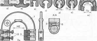
and clamping workpieces during external cylindrical grinding, various chucks and mandrels, drives and other devices are used. Installing the workpiece 2 (Fig. 13.24) in the non-rotating front 6 and rear 3 centers eliminates the influence on the machining accuracy (circle 1) of the bearings and spindle. Center 6 is installed in the conical hole of the spindle 5 of the headstock, and center 3 is installed in the conical hole of the quill 10 of the tailstock. Rotation of the workpiece is transmitted from the electric motor through the V-belt drive pulley 7 by means of the driving disk 4, pin 8 and clamp 9. The dimensions of the centers used are standardized (they are distinguished by numbers). Center holes are made at the ends of the workpiece (Fig. 13.25). The conical surfaces of these holes mate with the conical surfaces of centers 3 and 6. The angle at the apex of the cone of the center hole is usually 60° (Fig. 13.25, a). In some cases, to protect the main seating surface from damage, a safety cone with an angle of 120° is made (Fig. 13.25, b). With increased requirements for processing accuracy, a cylindrical safety groove is performed (Fig. 13.25, c). To reduce processing errors and increase the accuracy of workpiece installation, center holes with a curved generatrix (Fig. 13.25.2) and spherical holes (Fig. 13.25, d) are used. Workpieces with holes or recesses with a diameter of more than 15 mm at the end are processed in fungal centers. class=”aligncenter” width=”1362″ height=”1097″|fcw3qayjh5a| src=»https://mgplm.org/_pu/1/00642539.jpg» class=»aligncenter» width=»791″ height=»828″[/img] the holes are lubricated to reduce friction between the centers and the workpiece. The length of the protruding part of the rear center should exceed the height of the grinding wheel by 10-12 mm to ensure its free exit from contact with the workpiece at the moment of reversing the longitudinal movement of the table. Heavy parts and parts with holes that have narrow centering chamfers are processed on rotating centers. Workpieces with holes are ground on mandrels. The designs of mandrels are varied. According to the method of fastening on the machine, mandrels are divided into center (Fig. 13.26, a, b, c) and cantilever (Fig. 13.26, d, e); according to the method of installing the workpiece - rigid (Fig. 13.26, a, e, f) and expanding (Fig. 13.26, b, c, d). The center holes of the mandrels must be precisely machined and hardened. Expanding mandrels are used when processing thin-walled workpieces. For collet mandrels (Fig. 13.26, c), collet 2 with longitudinal slots, moving with nut 5 along cone 3, elastically unclenches and secures the workpiece 4. The pin prevents it from turning, and nut 1 serves to remove the workpiece. The cantilever ball mandrel (Fig. 13.26, d) is designed for installing and securing short workpieces. They can clamp workpieces with a difference in diameter of 5 microns. Under the action of screw 5, the separator moves and the balls move apart, centering the workpiece and simultaneously pressing it against the axial stop. Expanding mandrels include mandrels with a hydraulic or hydroplastic clamp (Fig. 13.27). Clamping of the workpiece occurs due to the deformation of a thin-walled cylinder under uniform pressure. A sleeve 2 and a centering sleeve 4 are pressed onto the body, secured with a screw 6. Hydroplastic 5 is poured between the body and the sleeve. The clamping force is transmitted by a plunger 3 through screw 1. The transmission of torque from the machine faceplate to the mandrels with workpieces is carried out by various drivers, clamps and chucks (Fig. 13.28), including self-centering three-jaw, membrane, etc. The use of chucks with self-clamping jaws reduces the time for securing workpieces. When securing the mandrel with the workpiece in the centers (Fig. 13.28, d) (position //), the clamping jaws 3, moving in the radial direction along the slot, turn
are placed on axis 4 and compress springs 2 and 5. Head 1 also occupies an equilibrium position, since it can move along the end surface of the cartridge within the gaps between the holes and bolts 7. In the free state (position /), the equilibrium state of head 1 is ensured by flat springs 6. Installation of workpieces with a hole in membrane cartridges ensures high processing accuracy (Fig. 13.29). The workpiece 6 is mounted on cams 5, mounted on a membrane disk 4 connected to a faceplate 3 on the spindle 2 of the machine. When the rod / (connected to a hydraulic or pneumatic cylinder) moves from right to left, disk 4 bends. This brings the cams closer to the center, which ensures that the workpiece is positioned along the hole. When the rod moves to its original position, the cams clamp the workpiece along the hole. When grinding long workpieces (lead screws, hydraulic cylinder rods, etc.) under the action of cutting force, the workpiece deflects due to its insufficient rigidity. For
To eliminate deflection, one or more steady rests are used - additional supports for the workpiece being ground. The designs of lunettes are varied. Housing 7 (Fig. 13.30) of an adjustable steady rest for a cylindrical grinding machine is installed on its table /. Blocks 4, 6 serve to absorb the radial and tangential components of the cutting force while supporting the workpiece 5. Block 4 is brought to the workpiece with a screw 3, and block 6 - with a screw 2 and a two-arm lever located on the axis 8. The blocks are made of wood or non-ferrous metal to avoid damage to the sanded surface. Author — nastia19071991
Gear grinding
Gears are part of a wide variety of mechanisms. The complexity of the shape of the working part determines that special grinding equipment has to be used. Among the features of this technology, we note the following points:
- The profile of the ring gear is processed.
- The circle changes to the size of the tooth involute.
- Special machines are suitable for working with gears.
Gear grinding
Often the tooth surface is hardened, which makes the machining process significantly more complicated.
Content
- 1 Process
- 2 Equipment 2.1 Types of surface grinding machines 2.1.1 Horizontal spindle (peripheral) surface grinding machines
- 2.1.2 Vertical spindle (grinding) machines
- 2.1.3 Disc sanders and double disc sanders.[3]
- 6.1 Bibliography
Centerless grinding
This technology is characterized by the fact that the workpiece is not fixed in the centers. In this case, grinding of metal parts takes place by applying rotation to only two grinding wheels, between which the workpiece is placed. In the central part there is a knife made of stainless steel. It eliminates the possibility that the product will fail due to displacement or become slightly jammed.
The use of such equipment can significantly speed up the grinding process. This is due to the fact that two abrasive wheels are used at once. There are simply a huge number of machines on sale that operate on the principle of centerless grinding.
Centerless grinding
Types of tools
The grinding wheel is the main tool for abrasive processing of metal, stone and wood products. The wheel consists of an abrasive base and a mineral, synthetic or ceramic binder. For processing, both stationary machines and hand-held electric or pneumatic tools can be used.
When choosing a wheel, it is necessary to take into account the abrasive bond material:
- The ceramic bonded grinding wheel allows you to process hard alloys.
- Bakelite bonded tools are used for processing natural stones, granite, marble, concrete and brick.
- Vulcanite bonded wheels are used for final polishing of metals.
The second commonly used type of abrasive tool is the sanding belt. It can be used both for manual processing and as an attachment for a grinder. The tape consists of a paper or fabric base, onto which a layer of abrasive is sprayed.
Sanding flat surfaces
Flat body blanks made of various metals are often processed. The operation to change the surface roughness is characterized by the following features:
- The workpiece is placed on a special table, which ensures reliable fastening. Fixation can be mechanical or magnetic.
- The main rotation is transmitted to the abrasive wheel, reciprocating the workpiece or tool.
Sanding flat surfaces
By selecting a wheel with the most suitable profile, it is possible to process the most complex shapes. During operation, coolant can be supplied to the contact area between the tool and the workpiece.
Process
Surface grinding is the most common grinding operation. It is a finishing process in which a rotating abrasive wheel is used to smooth the flat surface of metallic or non-metallic materials to give them a more refined appearance, removing oxide layer and contaminants from the surfaces of the machined parts. This will also allow you to obtain the desired surface for functional purposes.
A surface grinder consists of an abrasive wheel, a clamping device known as a chuck, and a reciprocating or rotary table. The chuck holds the material in place during processing. This can be done in two ways: ferromagnetic parts are held in place using a magnetic clamp, while non-ferromagnetic and non-metallic parts are held in place using vacuum or mechanical means. A machine vice (made of ferromagnetic steel or cast iron), placed on a magnetic chuck, can be used to hold non-ferromagnetic parts if only a magnetic chuck is available.
Factors to consider in surface grinding are the material of the grinding wheel and the material of the workpiece.
Typical workpiece materials include cast iron and mild steel. These two materials do not clog the grinding wheel during processing. Other materials include aluminum, stainless steel, brass and some plastics. When grinding at high temperatures, the material tends to weaken and is more prone to corrosion. This may also result in loss of magnetism in materials where applicable.
The grinding wheel is not limited to a cylindrical shape and can have many options that can be useful in conveying different geometries to the object being processed. The operator can straighten straight wheels to create custom geometries. When sanding the surface of an object, keep in mind that the shape of the circle will be transferred to the material of the object as an inverted image.
Sparks
is a term used when looking up precision values and literally means "until the sparks go out (no more)." It consists of passing the workpiece under the wheel without changing the depth of cut more than once, and as a rule, many times. This ensures that any discrepancies in the machine or workpiece are corrected.
Processing parts before grinding
As previously noted, sanding is the finishing step. Before it is carried out:
- Rough turning of metal. Due to this operation, the workpieces are given the required shape and dimensions, taking into account the allowance.
- Finish turning is carried out to give the required dimensions.
- Milling is another technological operation that involves mechanical removal of metal. Most often, housing parts and gears are milled.
- Heat treatment. In order to significantly increase the surface hardness and strength of the product, hardening is carried out. The fragility of the structure can be reduced by tempering and annealing. In some cases, thermochemical treatment is carried out, which involves introducing certain chemicals into the surface layer.
Processing parts before grinding
When developing processing modes, allowance for all technological operations is taken into account.
Definition and purpose of grinding
Grinding may be a final operation or may precede polishing. Polishing is a technological finishing process to reduce roughness. Gives the product an attractive appearance. It is used for decorative finishing, finishing of surfaces of various types and before metal coating. Grinding and polishing make the surface of a part or product smooth; in some cases, defects are eliminated using these operations. These may be shallow scratches, scratches, residues of slag or fine metal dust, traces of heat treatment. The performance characteristics of machines, machines, and instruments depend on the geometry of surface roughness. These include:
- reliability of connection with transitional and fixed landings;
- wear resistance;
- contact rigidity;
- thermal conductivity;
- tightness;
- electrical conductivity.
Processing using grinding equipment and materials is carried out by removing a given allowance with correcting errors in the shape and position of the surfaces that are being ground.
Characteristics and marking of abrasive tools
In most cases, when grinding metal, an abrasive tool is used. It is represented by a combination of a large number of grains, which are interconnected by a special lubricant. The circle is characterized by the following properties:
- Form. The working part may vary depending on what type of surface will be processed.
- Dimensions. The abrasive wheel is also selected by size depending on the dimensions of the surface being treated.
- Type of material used in manufacturing. The crumb can be made from crumbs of different hardness. Diamond chips are characterized by greater resistance to abrasion.
- Grain size. For fine grinding of metal, a wheel with the smallest grain size is selected. However, as the grit size decreases, the required time to complete processing increases.
- Surface hardness. This parameter is one of the main ones, indicated during labeling.
- Mounting hole size. It is taken into account when selecting a wheel for the characteristics of the machine.
The production of abrasive materials is carried out in accordance with established standards and technical conditions.
Circle markings are used to indicate the type of material used in manufacturing. Electrocorundum is artificial corundum based on aluminum oxide. There are several varieties of circles available for sale:
- Normal 14A and 15A, 16A.
- White 22A, 23A and 24A.
- Chrome 32A and 33A.
- Spherocorundum ES.
Silicon carbide can also be used. There are two types of stamps on sale: black and green. Boron carbide is marked with the letters KB. Recently, the most popular options are made from synthetic diamond; they are marked ACP and ASO, ARV and ARC.
Abrasive materials
Types of abrasives for grinding
Abrasives are small particles of a substance used for mechanical processing of products, and they can be of either natural or artificial origin. The main characteristics of abrasives for grinding are grain size, mechanical strength, microhardness and brittleness. They are divided according to the following characteristics: hardness (soft, hard, superhard), abrasive grain size (extra fine, fine, medium and coarse). Natural abrasives include chalk, quartz, emery, garnet, corundum, infusor earth, pumice, feldspar, tripoli, red ironstone and diamond.
Materials of artificial origin include: chromium and zirconium oxides;
- titanium dioxide, cerium and tin;
- nitrides of carbon, aluminum, silicon and boron;
- electrocorundum;
- alloys boron - carbon - silicon and titanium carbide - scandium carbide;
- synthetic diamond.
Diamond grinding is the highest quality in its abrasive properties.
Classification of non-ferrous metals
Non-ferrous metals have a characteristic shade and high ductility. They are extracted from the earth's rocks, where they are found in very small quantities. Processing non-ferrous metals is a labor-intensive and financially demanding process, but it brings huge profits. Products made from them have unique characteristics that are not available when made from ferrous materials.
All non-ferrous metals are divided into several groups according to their properties:
- heavy (tin, zinc, lead);
- light (titanium, lithium, sodium, magnesium);
- minor (antimony, arsenic, mercury, cadmium);
- scattered (germanium, selenium, tellurium);
- precious (platinum, gold, silver);
- radioactive (plutonium, radium, uranium);
- refractory (vanadium, tungsten, chromium, manganese).
The choice of the group of non-ferrous metals used in production depends on the desired properties of the final product.
Basic properties
Copper is a ductile metal with good thermal conductivity, but low electrical resistance. It has a golden color with a pink tint. It is rarely used independently; more often it is added to alloys. Metal is used to make instruments, machines, and electrical equipment.
Bronze is the most popular copper alloy and is produced by adding tin and chemicals. The resulting raw material has strength, flexibility, ductility, is easy to forge and is difficult to wear.
Aluminum conducts electricity well and is a ductile metal. It has a silver tint and is light in weight. Fragile, but resistant to corrosion. Used in military affairs, food industry and related industries.
Zinc is a rather brittle non-ferrous metal, but it is resistant to corrosion and ductile if heated to a temperature of 100–150 ºC. With its help, a corrosion-resistant coating is created on products, as well as various steel alloys.
When choosing a non-ferrous metal for a future part, you need to take into account its properties, know all the advantages and disadvantages, and also consider alloy options. This will allow you to create the highest quality product with the specified characteristics.