In the household, problems arise when installing sockets and switches, connecting lighting systems, household electrical appliances and other similar devices. They are usually powered from single-phase sources, the wires of which consist of two conductors - phase and neutral. In a safer option, a third wire is added to them - ground or grounding.
Most household electrical appliances function normally when the conductors are connected strictly according to the operating diagram. The basis for successfully resolving the issue will be the skills of determining where the phase is and where the zero is. You can do this fairly simple job yourself, without involving electricians, and therefore save on financial costs.
There are ways to find phase and zero, both with and without the use of instruments.
The concepts of “zero” and “phase”
Electric current is the ordered movement of negatively charged particles.
If electrons move in only one direction, such a current is called constant; if in different directions, it is called alternating.
There are three types of conductors:
- “Phase” is a working contact. Voltage is applied to it.
- “Zero” (“zero”) is the conductor through which current flows back to the generator, completing the circuit.
- “Ground” is a wire connecting any point in the network to a grounding element. It is needed to protect against electric shock.
Why does the multimeter need to be switched to voltmeter mode when checking the phase?
Before the mass appearance of digital devices on sale, friends and acquaintances often brought burnt analog testers to our electrical laboratory for repair.
The reason for their damage was almost always the same: incorrect choice of measurement mode when connecting the device to voltage circuits.
In this case, in the best case, the connection chains of resistors with buttons and switches burned out, and in the worst case, the highly sensitive measuring head with current-carrying springs burned out. The latest malfunctions most often could not be repaired.
People simply did not understand that the tester, like a digital multimeter, makes measurements based on Ohm's law.
The only difference is that the tester works with analog values, while the multimeter works with digital values. But the principles for connecting both types of devices are the same and come down to two simple rules:
- when measuring voltage, the switches are placed in the position that introduces a calibrated resistance that limits the current through the current measuring head or sensor;
- measurement of an unknown voltage value must always be performed at the maximum scale value of the device.
Incorrect position of the switches that switch the device to ohmmeter or ammeter mode is most often found among beginners due to inattention and low skills.
I remember a case where two experienced electricians, relying on each other in a hurry, burned an expensive model voltmeter - a standard of accuracy class 0.2.
The device had to be urgently used to set the settings for the 220-volt operating current battery charger at a 330 kV substation.
One worker held the device horizontally in his hands and handed the ends with probes to the second to take measurements. None of them noticed that the switch was at the lowest limit of measurement. As a result of the flow of increased current, the measuring head burned out completely.
This case is not typical, but it clearly shows that electricity does not forgive anyone any mistakes. Current flows where there is less resistance.
Incorrect connection of a multimeter or tester to voltage circuits, in addition to damaging the measuring device itself, creates a short circuit that is harmful to household consumers and wiring.
Therefore, before installing measuring probes on the voltage circuit, it is necessary to check the initial position of the device switches in voltmeter mode.
In fact, it is worth noting that high-end digital multimeters are equipped with a built-in electronic circuit that protects the device from improper connection to voltage circuits, while budget models do not have it.
It is popularly called “foolproof.” In many cases, it can save the device and the household network, but I still do not recommend constantly using these capabilities: always connect the voltmeter correctly.
Why is it important to correctly identify the phase wire
When connecting devices to the network, a working “phase” conductor is used. Voltage is supplied directly to the consumption source. It would be a mistake to connect the receiver to “zero”, because when the circuit is opened (the device is turned off), the network still remains energized. This can be clearly seen if you connect a light bulb switch to the neutral wire. In this case, the cartridge is constantly under voltage. This connection is dangerous when it is necessary to change the lamp or the lampshade itself.
It is important to correctly identify the phase wire.
General information
In our daily lives, we encounter electricity almost everywhere we go. Whether it’s work or various institutions: cinema, theater, shops, sports complexes - the list could go on for a very long time. Needless to say, we use many electrical appliances every day, and 20 or 30 years ago there were not as many of them as there are now. Moreover, their number is growing with enviable frequency.
But all electrical equipment cannot work forever and sooner or later it begins to break down, which is simply inevitable. No one has yet invented a perpetual motion machine, so you shouldn’t hope for a miracle. Some people want to learn something new, unknown, and electricity is no exception. If only because you can carry out repairs of household appliances yourself. Of course, it is better to invite a specialist, but you can do light work yourself. Only for this it is necessary to study fundamental concepts in order to understand what zero and phase are.
Methods for determining the working “phase” and “zero” using instruments
The conductor with the working “phase” has the same voltage as in the outlet: 220V. It is necessary for the functioning of household electrical appliances. In the neutral conductor the current voltage is very weak. Identification of wires is carried out by elimination method as soon as phase contact is detected.
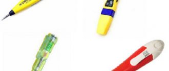
There are several ways to determine the “phase”: by the color of the wires, by letter markings and using instruments - an indicator screwdriver and a multimeter.
Indicator screwdriver
The design of the screwdriver ensures its convenient and safe use.
The voltage value cannot be determined using an indicator screwdriver - it only shows its presence in the conductor.
Before checking the voltage, you need to perform a number of manipulations for safety:
- de-energizes the network;
- strip the wires of insulating material;
- separate the ends of the wires from each other as far as possible to avoid a short circuit;
- turn on the current in the network.
The indicator screwdriver shows the presence of current in the conductor.
The diagnosis itself is very simple:
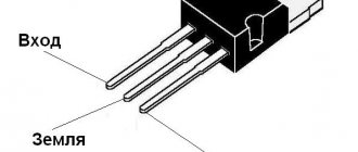
- You need to touch the bare wires one by one with the tip of the tool. At the same time, you need to hold the screwdriver by the handle with your thumb and middle finger. It is dangerous to touch the metal rod during the test, because current passes through it.
- At the same time, use your index finger to press on the metal tab at the end of the screwdriver. By touching the contact pad, a person acts as an element of the circuit, grounding it. If there is voltage in the conductor, the LED light will light up; otherwise, the conductor is neutral.
A resistor is built into the design of the indicator screwdriver, which limits the current to a value safe for humans. Using a spring, it transmits a signal to the light bulb.
This method is especially convenient when checking sockets, since the tip of the screwdriver allows you to quickly reach the contact.
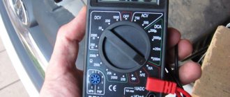
Multimeter
Using a multimeter, all characteristics of the electrical network are measured. Accordingly, it also shows the presence of voltage in the conductor. In addition, the device determines the nature of each wire - “ground”, “zero” and “phase”. It is possible to measure voltage on any part of the circuit, be it a panel, socket or cable.
Procedure:
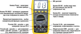
- To check the phase, set the device to “Alternating voltage” mode. Select the maximum permissible limit: 600-750 V.
- One probe of the multimeter is held between the fingers, and the other is touched to the contact. Insignificant voltage readings will correspond to “zero”, and numbers close to 220 V characterize “phase”.
When an electrician, when checking, clamps one probe with his fingers, it does not receive an electric shock due to the fact that the multimeter has a large input internal resistance, and the currents are hundredths of a milliampere.
Due to internal resistance in the device, different models may show different numbers. But this is not critical.
The multimeter measures all characteristics of the electrical network.
It is important not to confuse the modes when testing. If the examiner accidentally selects "Current Measurement" and touches one of the probes with their hand during identification, they will receive an electrical shock.
It is not necessary to clamp the probe with your fingers for grounding purposes. Some outlets already have a ground contact installed. A metal heating system pipe can also serve this purpose, and electricians often use it.
Having determined the “phase” using a tester, calculating “zero” and “ground” becomes easier.
If you touch the “phase” with one probe and the “zero” with the other, the device will show 220 V. And when the “phase” and “ground” are closed, the value will be much less than 220 V.
How more complex, active indicator screwdrivers work
The simplest indicator screwdrivers use the contact measurement method, that is, to determine the presence of voltage, you must touch the tip to the conductor. This is quite convenient, but does not solve most of the problems that electricians face when troubleshooting electrical networks.
instruction manual for indicator screwdriver (click to enlarge)
More advanced models of indicator screwdrivers can work in a non-contact manner - they respond to the electromagnetic field that arises in any conductor when electric current flows through it. The design of such postcards is much more complicated - they already have their own circuit and separate power supply. Most are equipped with sound indication. Indicator screwdrivers with an LCD screen are a separate category - such models can even show what voltage is in the network being measured.
The principle of operation is very simple - there is a coil in the screwdriver and when it enters the field around the conductor, an electric current appears in it, which causes the indicator lamp to light up and the buzzer to sound. This property of non-contact indicator screwdrivers allows you to find breaks in the wiring even through the wall - without such a device you would have to completely remove the wallpaper and knock down the plaster wherever the wire is laid.
Before using an indicator screwdriver with the ability to non-contactly determine the presence of voltage, you must remember to turn on their power - so that the battery does not run out, they have a switch.
You can learn how to use this indicator screwdriver by watching this short video instruction:
In addition to indicator screwdrivers, there are other types of voltage detectors, which you can learn about by reading this article.
Alternative methods without the use of instruments
If the situation is such that there is neither an indicator screwdriver nor a multimeter, but it is necessary to find out which contact is phase, use a visual method for determining the contact.
On the cable there is often a letter designation of the characteristics of the conductors. So, the letter L is assigned to the “phase”, N to the “zero”, and PE to the “earth”.
Sometimes electricians during installation additionally mark the phase wire with a hanging tag with a designation. But a simpler solution is color coding of wires. Connecting them correctly (in accordance with the standard) subsequently makes the work of electricians easier, allowing them to quickly navigate the wiring.
By wire color
The colors of the wire insulation are selected so that they differ as much as possible from each other:
- The "phase" is often white, black or brown.
- “Zero” - blue and its shades.
- "Earth" - yellow-green.
But the standards for connecting conductors are not always observed. Therefore, for the sake of safety, it is better to check the voltage in the wires, regardless of their visual markings.
Wire marking standard
Using a control lamp
This method is considered the most risky, but it helps out in situations where the usual testers are not at hand. The inspector needs a lamp twisted into a socket from which 2 wires come out. To safely use such a “device,” it is better to attach probes to the ends of the wires and wrap the lamp itself with a protective casing.
You need to touch the metal pipe (or other grounding element) with one lamp tap, and check the contact with the other. If the lamp lights up, then the contact being diagnosed is “phase”.
Conductors can also be identified by exclusion:
- Alternately touch the lamp taps to two of the three contacts that need to be identified. If the lamp is on, it means that the “phase” - “zero” pair is engaged at this moment.
- To determine the phase and neutral conductors, one of the tester taps is used to touch the next of the three contacts being tested. The light goes out when disconnected from the “phase”. But this will only happen if a circuit breaker is installed in the network. If it is absent, the indicator lights up even in the “ground” - “zero” position.
- To identify the “ground”, if a circuit breaker is not installed, remove the ground from the cable and repeat the test. Now the lamp will not light on this conductor.
Assembling a control light at home is not difficult. To do this, you will need 2 conductors connected to the socket, and the light bulb itself screwed into it.
For safety reasons, it is better to use a neon lamp, and electricians recommend attaching probes to the wires - this will secure and facilitate the operation of the “control”.
Since the light bulb method is unsafe, it is best to avoid it.
Control potato
The most unusual method of determining the phase will require 2 wires and potatoes. 2 conductors are inserted into a tuber cut in half at the maximum distance from each other. One is placed over something grounded (a heating system pipe), the other is placed over the contact being tested. After 5-10 minutes, inspect the potato cut. If a spot appears on it, then the conductor being tested is a “phase”. If there is no spot - “zero”.
Other verification options
In addition to the listed methods for checking phase and zero with a multimeter, there is a test using a control llama. The method is quite unusual and requires special care, but it is effective.
For such a device you need a socket, a lamp, and a wire with the insulation cut off at the ends. When using a lamp, it will be possible to determine whether there is a phase or not, but it will not be possible to establish which phase conductor. If, when connecting the wiring of the test lamp to the identified conductors, it lights up, then one of the wires is phase, and the second is most likely zero. If it does not light up, then there is either no phase or zero, which is also possible.
Useful tips and general recommendations
Working with electrical wiring requires care and caution.
Electricians advise:
- Do not rely entirely on the color differentiation of wires or their markings; check the contacts with testers again. Cases of violation of electrical installation standards are not uncommon.
- If possible, avoid determining the voltage in conductors using a “tester” or a potato. Such methods are considered extreme, and it is better not to abuse them without experience.
- When using a multimeter, read the instructions in detail before use. Pay attention to the device settings.
Installing wiring according to standards will facilitate further connection of receivers and extend the service life of the entire electrical network. In addition, compliance with the necessary installation standards will make electricity consumption comfortable and safe.
Application area
The presented tool will be able to perform not only the simplest functions - how to determine the phase with an indicator screwdriver - but also many additional ones.
It is possible to check the cable for breaks, the serviceability of the extension cord, and detect wiring in the wall.
All functions must be carried out according to specific instructions for using an indicator screwdriver. Measurements can be made by contact or non-contact method.
The contact method will help you find the voltage in the AC network. This is the simplest procedure. The probe of the tool touches the exposed cable. If the LED lights up, it means the phase has been found. If the indicator does not light up, it may be the neutral wire, and this also happens when there is no power in the network or its break.
The non-contact method will help you find hidden wiring. To do this, the handle is brought to the surface behind which the wire is located. If the neon element lights up, the conductor has been found.
Visual inspection algorithm
First, open the shield. Carefully consider circuit breakers, the number of which depends on the rated load. There are 2 connection options for the machines:
- the wire contains only a phase;
- both phase and zero.
The ground wire is connected directly to the busbar.
Now that you know the meaning of the colors and the location of the cables, all that remains is to check that everything in the panel complies with the standard.
Next, provided that your wire insulation in the panel complies with the rules, you need to open each junction box and visually examine the condition of the twists. There should be no inaccuracies here either.
Very often there are moments that you should not focus on. For example:.
- The distribution box contains a switch connected to the phase.
- The installers used wires with two cores, the insulation of which differed from the standard.
Be sure to adhere to safety regulations and be careful and extremely attentive when solving electrical problems yourself.