The owner of an apartment or private house who decides to carry out any procedure related to electricity, be it installing a socket or switch, hanging a chandelier or wall lamp, is invariably faced with the need to determine where the phase and neutral wires are located at the place of work, as well as the grounding cable. This is necessary in order to correctly connect the mounted element, as well as to avoid accidental electric shock. If you have some experience working with electricity, then this question will not confuse you, but for a beginner it can be a serious problem. In this article we will understand what phase and zero are in electrics, and we will tell you how to find these cables in a circuit, distinguishing them from each other.
What is the difference between a phase conductor and a neutral conductor?
The purpose of the phase cable is to supply electrical energy to the desired location. If we talk about a three-phase electrical network, then there are three current-supply wires per single zero wire (neutral). This is due to the fact that the flow of electrons in a circuit of this type has a phase shift of 120 degrees, and the presence of one neutral cable in it is quite sufficient. The potential difference on the phase wire is 220V, while the zero wire, like the ground wire, is not energized. On a pair of phase conductors the voltage value is 380 V.
Line cables are designed to connect the load phase to the generator phase. The purpose of the neutral wire (working zero) is to connect the zeros of the load and the generator. From the generator, the flow of electrons moves to the load along linear conductors, and its reverse movement occurs through neutral cables.
The neutral wire, as mentioned above, is not energized. This conductor performs a protective function.
The purpose of the neutral wire is to create a chain with a low resistance value, so that in the event of a short circuit, the current is sufficient to immediately trigger the emergency shutdown device.
Thus, damage to the installation will be followed by its rapid disconnection from the general network.
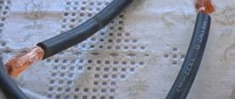
In modern wiring, the sheath of the neutral conductor is blue or light blue. In old circuits, the working neutral wire (neutral) is combined with the protective wire. This cable has a yellow-green coating.
Depending on the purpose of the power transmission line, it may have:
- Solidly grounded neutral cable.
- Insulated neutral wire.
- Effectively grounded neutral.
The first type of lines is increasingly used in the design of modern residential buildings.
In order for such a network to function correctly, the energy for it is generated by three-phase generators and is also delivered through three phase conductors under high voltage. The working zero, which is the fourth wire, is supplied from the same generator set.
Visually about the difference between phase and zero in the video:
Basic concepts.
Current strength is a scalar physical quantity equal to the ratio of the charge passing through the conductor to the time during which this charge passed.
where
I is the current strength, q is the amount of charge (amount of electricity), t is the charge transit time.
Current density is a vector physical quantity equal to the ratio of the current strength to the cross-sectional area of the conductor.
where
j
is
the current density
,
S
is
the cross-sectional area of the conductor.
The direction of the current density vector coincides with the direction of motion of positively charged particles.
Voltage
-
a scalar physical quantity equal to the ratio of the total work of Coulomb and external forces when moving a positive charge in an area to the value of this charge.
where A is the total work of external and Coulomb forces, q is the electric charge.
Electrical resistance is a physical quantity that characterizes the electrical properties of a section of a circuit.
where ρ is the resistivity of the conductor, l is the length of the conductor section, S is the cross-sectional area of the conductor.
Conductivity is the reciprocal of resistance
where G is conductivity.
What is a grounding cable for?
Grounding is provided in all modern electrical household devices. It helps reduce the current to a level that is safe for health, redirecting most of the flow of electrons to the ground and protecting the person touching the device from electrical shock. Also, grounding devices are an integral part of lightning rods on buildings - through them, a powerful electric charge from the external environment goes into the ground, without causing harm to people and animals, or causing a fire.
To the question - how to identify a grounding wire - one could answer: by the yellow-green sheath, but color marking, unfortunately, is often not observed. It also happens that an electrician who does not have sufficient experience confuses a phase cable with a neutral cable, or even connects two phases at once.
To avoid such troubles, you need to be able to distinguish conductors not only by the color of the sheath, but also in other ways that guarantee the correct result.
How should grounding be carried out in a three-wire network?
At the moment, in most new buildings, a three-wire network is installed, in which there is a phase, neutral and grounding (yellow-green wire). “Zero” and “ground” are connected in the shield to one grounding bus, but not under a common contact clamp ( PUE 7.1.36 ). The ground is then connected to each outlet in one continuous wire. Most modern electrical equipment already has a third grounding pin on the plug, which provides grounding to the chassis when it is plugged into an outlet.
Home electrical wiring: finding zero and phase
You can determine at home where which wire is located in different ways. We will analyze only the most common ones that are accessible to almost anyone: using an ordinary light bulb, an indicator screwdriver and a tester (multimeter).
About the color marking of phase, neutral and ground wires in the video:
Checking with an electric lamp
Before you begin such a test, you need to assemble a testing device using a light bulb. To do this, it should be screwed into a cartridge of suitable diameter, and then secured to the wire terminal, removing the insulation from their ends with a stripper or an ordinary knife. Then the lamp conductors must be applied one at a time to the cores being tested. When the lamp lights up, it will mean that you have found a phase wire. If you check a cable with two cores, it is already clear that the second one will be zero.
Checking with an indicator screwdriver
A good assistant in work related to electrical installation is an indicator screwdriver. The operation of this inexpensive instrument is based on the principle of capacitive current flowing through the indicator body. It consists of the following main elements:
- A metal tip shaped like a flathead screwdriver that is applied to wires for testing.
- A neon light bulb that lights up when current passes through it, thus signaling phase potential.
- A resistor to limit the amount of electrical current that protects the device from combustion under the influence of a powerful flow of electrons.
- A contact pad that allows you to create a circuit when you touch it.
Professional electricians use more expensive LED indicators with two built-in batteries in their work, but a simple device made in China is quite accessible to anyone and should be available to every home owner.
If you check the presence of voltage on the wire using this device in daylight, you will have to look more closely during the work, since the glow of the signal lamp will be difficult to see.
When the screwdriver tip touches the phase contact, the indicator lights up. In this case, it should not light up either at the protective zero or at the grounding, otherwise we can conclude that there are problems in the connection diagram.
When using this indicator, be careful not to accidentally touch a live wire with your hand.
About determining the phase clearly in the video:
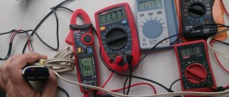
Checking with a multimeter
To determine the phase using a home tester, you need to put the device in voltmeter mode and measure the voltage between the contacts in pairs. Between the phase and any other wire, this indicator should be 220 V, and applying probes to the ground and protective zero should show the absence of voltage.
Additional information about finding the ground, phase, neutral wire
Let's add another method - it is prohibited by industry. A light bulb in a socket with two exposed wires. Using the tool, the phase is found, and the wire can be short-circuited to ground. You cannot use water, gas, sewer pipes or other engineering structures. According to the rules, the cable antenna braid is equipped with grounding (grounding). With respect to it, you can use a tester (a light bulb in a socket prohibited by standards) to find the phase.
For determined people, we recommend fire escapes and steel tires for lightning rods. You need to clean the metal until it shines, call the phase phase
Please note that not all fire escapes are grounded (although they must be), lightning rod buses are 100%. If you discover such blatant arbitrariness, you can contact the management organizations; if there is no response, knock (Russians call human rights activists informers) to government agencies
Indicate a violation of the rules for protective grounding of buildings.
Sources of interference on the ground bus
All interference affecting cables, sensors, actuators, controllers and metal automation cabinets, in most cases, also flows through the grounding conductors, creating a parasitic electromagnetic field around them and a drop in the interference voltage on the conductors.
Sources and causes of interference can be lightning, static electricity, electromagnetic radiation, “noisy” equipment, a 220 V power supply with a frequency of 50 Hz, switched network loads, triboelectricity, galvanic couples, the thermoelectric effect, electrolytic processes, conductor movement in a magnetic field, etc. In industry, there is a lot of interference associated with malfunctions or the use of uncertified equipment. In Russia, the level of interference is regulated by standards - GOST R 51318.14.1, GOST R 51318.14.2, GOST R 51317.3.2, GOST R 51317.3.3, GOST R 51317.4.2, GOST 51317.4.4, GOST R 51317.4.11, GOST R 51522, GOST R 50648. At the design stage of industrial equipment, in order to reduce the level of interference, they use a low-power element base with minimal speed and try to reduce the length of conductors and shielding.
Wiring colors as a way to speed up installation
The correct coloring of the wiring speeds up the installation of electrical wiring.
Before GOST R 50462-2009 came into effect, cables were marked white or black. The phase and zero were determined when the control switch was turned off at the moment of power supply.
The use of color markers simplifies repair work, ensures safety and convenience. Based on the shade of the cables, the master will not spend much time connecting electricity to a house or apartment.
You can consider the meaning of color marking using the example of a lamp. If the lamp is changed and the zero and phase are reversed, there is a risk of injury or death from electric shock. When in electrics the designation L and N is made by color, the phase will go to the switch, and zero will go to the light source. The voltage will be neutralized, and you will be able to touch even a light bulb that is on.
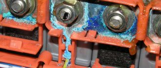
Common problems and their solutions
If the neutral wire breaks, an emergency operation of the 3-phase network occurs. Due to the combustion of the working zero, in the case of unequal load, a very low or, conversely, high voltage is created on single-phase devices connected to this network, which exceeds the rated value characteristic of a single-phase circuit.
As a result, electrical equipment fails. This primarily applies to expensive electronic devices:
- computers;
- TVs;
- washing machines.
Such household appliances are most sensitive to fluctuations in the power supply voltage, especially to its increase.
The voltage to ground is greater than the phase voltage. That's how it should be
A private house. I made grounding - 15m 10ka reinforcement + 2m strip in the ground, the rest is on the surface. Zero-phase voltage 216 Ground-phase voltage 222 V, i.e. more. Is this normal? If the value is ground-zero, the tester shows 3 V.
The quality of grounding is determined by resistance.
Well, in general, at zero the potential is usually different from zero)) But this is not normal. Re-ground the zero on the input support - and then the zero will be zero
It’s as if we have a network with a grounded neutral by default. So feel free to land before entering the house
——————Long live temporary difficulties!
If the author is very concerned about distortions and really wants symmetry, you can put an isolation transformer at the input (I can’t imagine the price) and make your own power supply system, preferably with a zero, separate from grounding.
Actually there are problems with the RCD
Did I understand correctly that if I connect zero to ground after the meter, then these 3 V will drive the meter around the clock? Or slow down?
------Guys let's be friends! (With)
The old counter most likely will not react to this. But the new electronic one will most likely count.
I also opened a similar topic. I decided not to do the ground. I limited myself to the RCD. Everything works.
Yes, I’m not going to do this, if only because of the 3 V on the body of any device. Another question: the RCD doesn’t care which side goes into the network, which side goes to the meter? Zero is marked there as zero and the phase is marked as 1 and 2.
------Guys let's be friends! (With)
By the way, if one wire from an electrical device is to a grounded pin, and the second is to a phase, it will work due to Chubais.
------temporary difficulties
The phase will still flow through the meter. At least to zero or into the ground. And such unfortunate economists need to be grounded alive! How many times, while working in apartment buildings, did I receive heating and plumbing problems?
------Guys let's be friends! (With)
not in the case of a detached house.
------temporary difficulties
I won’t say about today, but two years ago it worked with a new meter. Province, sir..
------temporary difficulties
even 2 years ago - you surprised me very much - well, you have to look at what province...
So as not to create more topics, can an RCD be installed on an unstabilized line? There are differences from 180 to 230.
In theory, it’s possible. It doesn’t monitor the voltage, but monitors its differences. those. if an equal amount of energy passes through zero and phase, it does not operate. In the event of a leak, a breakdown to the ground, and the like, the balance is disrupted and the circuit breaker is triggered.
Won't it knock out all the time?
Your situation regarding voltage drops is purely rural, maybe one of your comrades can tell you. Uzo is a capricious thing - it leaks a little and gets knocked out - the wiring must be of good quality. For me it works spontaneously 2-3 times a year, I don’t know the reasons, I just turn it on and that’s it.
I'm asking about the dacha)
In my village, differences of 180-230 ouzo works normally, it clearly triggers only for leaks, there haven’t been any false ones in a year.
I spoke with two electricians - both said that it would knock out, but with my head I understand that this should not happen, because it was absolutely rightly noted:
Yes, it’s clear which is better! Nobody argues. Will there be constant alarms on the dacha line? Otherwise, it will simply torture you and you will have to throw it away - money down the drain!
If I may. My machine guns are all Legrandovsky ones. Line 3-phase.
We started from the “dirty” zero, reached the RCD... What is the connection? Three volts at zero relative to the ground is simply nothing for rural areas. My neutral wire is re-grounded to the reinforcement of the reinforced concrete support from which the entry into the house is made. The three-phase RCD tripped only once in four years, during a thunderstorm. Personally, for me, it is better to allow false alarms than one accident.
The stepsons are reinforced concrete, the poles are already rotten, the transformer is dying.
How is the amperage of ouzo selected? Is 25 not enough?
I have a dedicated 5 kW, respectively, the input circuit breaker is 25 A, the ouzo must switch the same current.
And I have a 40 A automatic machine...
It's better to change the IEC to something more decent, IMHO.
Chinese crap.