What does electrician study?
Science began to develop rapidly in the 19th century. At that time, the first laws were discovered that made it possible to understand what electricity is. The theoretical foundations were tested in practice. The first electrical devices began to appear, and the means of transmitting electricity from sources to consumers improved.
Electrical science was based on discoveries in the fields of mathematics, physics, and chemistry. She studied the nature, properties of current, electromagnetic fields.
Modern science helps to learn everything about devices that use electricity. Thanks to research, more advanced devices are being created. Electrical engineering is a science that has become the main engine of progress.
Where to start learning
Electrical manuals “for dummies” are available on information portals. There is no shortage of such materials, so anyone can start studying the discipline from scratch. However, if a person plans to become an electrician, he will have to enroll in the appropriate faculty of a higher or secondary specialized educational institution.
University, technical school, college
Many educational institutions offer professional education as an electrician. It is worth considering the features of training in each of them:
- A full course at a university lasts 4-5 years. A minimum practical basis is given here. However, universities prepare specialists with good theoretical knowledge. Educational institutions accept graduates of 11th grade or secondary educational institutions.
- Technical schools provide an equal amount of theoretical and practical skills. The training is aimed at obtaining a working specialty. Therefore, the theory is studied in less detail than at a university. Technical schools accept graduates of the 9th or 11th grades of school. Training lasts 4 or 3 years, respectively.
- School or college. Such institutions prepare workers, so the theoretical part is kept to a minimum. You can get a profession as an electrician at a school in 1-3 years.
Courses
Such programs help you master basic skills in 2-8 weeks. Lessons are held both in standard and online mode. The disadvantage of the courses is the small amount of knowledge gained. A novice electrician learns the basics of electrical engineering and masters some skills. The student conducts practical classes independently.
All courses are offered on a paid basis, and you can take them without leaving another job.
Self-study
If the described teaching methods are not suitable, a person can master electrical engineering independently with the help of special literature. In this case, the electrician will not be able to perform complex tasks, but he will be able to install the wiring in the apartment. To become an experienced specialist with the help of tutorials, you need to undergo practical training as an electrician's assistant. The student must carefully monitor the actions of the mentor and complete simple tasks.
Formulas for direct electric current
A direct electric current does not change in magnitude or direction. It is used to calculate a closed, homogeneous circuit, power and other parameters. Therefore, it is important to know the formulas for it and the basic laws associated with it.
Ohm's law for a section of a homogeneous chain
For electric current to exist, a field is needed. For its formation, potentials or their difference, expressed by voltage, are needed. The current will be directed towards reducing the potentials, and the electrons will begin to move in the opposite direction. In 1826, G. Ohm conducted a study and concluded: the higher the voltage, the greater the current that passes through the section.
For your information! Adjacent conductors conduct electricity differently. That is, each element has its own conductivity, electrical resistance.
As a result, according to Ohm’s theorem, the current strength for a section of a homogeneous circuit will be directly proportional to the voltage across it and inversely proportional to the conductive resistance.
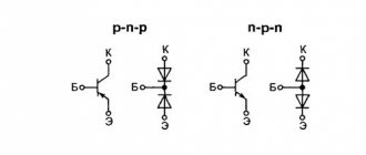
Ohm's law
Using the formula I = U / R, where I is considered to be the current strength, U is the voltage, and R is the electrical resistance, the latter value can be found if p * l / S, where p is the conductor resistivity, l is the length of the conductor, and S — cross-sectional area of the conductor.
Ohm's law for a closed circuit with a current source
Ohm made a formula for a closed circuit. According to it, the current in this section from a current source having internal and external load resistance is equal to dividing the electromotive force of the source by the sum of the internal and external resistance. It looks like this: I = e / R + r, where I is the current force, e is the emf, R is the resistance, and r is the internal resistance of the voltage source.
Note! In the physical sense, according to this law, the higher the EMF, the higher the source of energy, the greater the speed of movement of charges. The higher the resistance, the lower the current.
Ohm's law for a closed circuit
DC operation
Energy, when passed through a conductor, moves in an orderly manner into the carrier. While moving, it does work. As a result, direct current work is the field activity aimed at transferring electrical charges along a conductor. It is equal to I multiplied by the voltage and time performed by the work.
Joule-Lenz law
When electricity passes through any resistive conductor, heat is always released. The amount of heat released over a certain period of time is determined by the Joule-Lenz law. According to the formula, the heat power is equal to the electricity density multiplied by the voltage - w =j * E = oE(2).
Note! In practical terms, the law is important for reducing electricity loss, selecting a conductor for an electrical circuit, selecting an electric heating device and using a fuse to protect the network.
Joule-Lenz law
Electrical connection diagrams
There are 2 main types of circuits in which components are connected in parallel or in series. A novice electrician should study the principles of their construction and operation.
Parallel and serial
In the first case, electricity branches out into all the circuits connected to each other. The total current is equal to the sum of the values in each branch. Circuits connected in parallel receive the same voltage.
When constructing a circuit in series, current flows from one branch to another. A charge of equal strength passes through all circuits.
Kirchhoff's laws
The electrical work of any room is carried out in the form of closed, working electrical circuits. The two main laws that determine processes in electrical networks are Kirchhoff's laws. There are two of them. Both of them apply to both direct and alternating currents.
Kirchhoff's first law states:
The total value of currents directed to an electrical network node is equal to the total value of currents directed from the node.
In practice, the operation of Residual Current Devices (RCDs) is based on Kirchhoff's first law. The operation of the RCD is to turn off the power supply to the network when leakage currents occur. During normal operation, the total value of the current flowing into the electrical network is equal to the value of the current flowing out of it. If the equality of currents is violated, then there is a leak in the network. The RCD is designed and connected in such a way that if there is a current leak, the RCD detects it and disconnects the power supply.
Kirchhoff's second law states:
Any closed loop of an alternating electrical network has equal values of complex voltages and EMF (electromotive forces) on all passive elements of the network.
Note: Complex voltage is the value of AC mains voltage.
Practical application can be explained on any apartment power supply group. For clarification, let's look at an apartment.
No matter how many power supply groups there are in the apartment, at any outlet or lamp the voltage in the network (in operating mode) will be 220 volts.
Automatic protection systems
The power grid carries 2 types of threats:
- The power of household wiring is sufficient to ignite materials used in finishing premises. A short circuit in the network leads to an uncontrolled increase in current strength and ignition. It is impossible to reduce the likelihood of such a situation to zero, but it is reduced by introducing a circuit breaker into the circuit. When the current parameters increase, the device plate is deformed, a spring is released, which opens the contacts. The machine does not respond to starting current pulses.
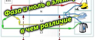
- The neutral wire is connected to the ground, the phase wire is energized in relation to it. A current arises between such a conductor and grounded objects. There is practically no risk of injury to a person by electricity generated between 2 network cables. However, under certain conditions of current flow, electrical injury becomes fatal. Automatic protection systems ensure that current enters one wire and leaves through the other. When voltage appears between the phase and a grounded object, for example, a human body, the RCD de-energizes the network.
Learning to read diagrams
The electrical circuit diagram of the device is actually not as confusing and incomprehensible as it seems at first glance, provided you know the symbols of the elements. As proof, we will now look together at the diagram for connecting an electric light bulb through a switch and fuse (Fig. 12).
Connection diagram for a light bulb via a switch and fuse
As can be seen from the figure, the light bulb is simply plugged into a socket, a switch is installed on one of the wires (usually a phase), a fuse (in truth, it is not needed in this circuit, but still...) protects the light bulb and wiring from burning out as a result of voltage surges or short circuit (which is also, in fact, a voltage surge, because the current strength increases significantly when the resistance sharply drops to zero - remember Ohm’s law). Having become a little familiar with the diagrams and theory (at least with its basics), I would like to quickly begin practical work. For example, make a mirror in the bathroom illuminated for your wife, but before starting such work, let’s talk a little more about the basics - knowledge of them (not even just knowledge, it should be in the blood and done automatically) can save nerves, health, and perhaps life.
Electrical installation work
The creation of electrical networks consists of several stages:
- design;
- preparation of materials and tools;
- wiring gaskets.
Required Tools
To work you will need:
- phase detector;
- pliers;
- wire cutters;
- knives;
- insulating tape;
- screwdrivers;
- multimeter for testing networks.
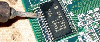
Removing vinyl insulation from wires (stripping)
The procedure is fraught with some difficulties. It must be carried out in such a way that the current-carrying core is not damaged. Sometimes each conductor is protected with vinyl insulation. A set of such tires is placed in another braid. In this case, you need to cut the top layer without damaging the internal insulation. To remove the braid, use a dull knife; to strip copper or aluminum conductors, use a sharp one.
When cutting insulation, the blade is inserted halfway through the thickness of the material. After this, the wires are pulled apart with pliers. The outer insulation breaks along the cut line.
Insulation
Places of connection or damage to the braid are carefully isolated. During electrical installation, a special tape is used for this. To begin with, the cores are insulated separately, then together. The adhesive applied to the electrical tape should provide a strong hold. The material is securely glued to the vinyl sheathing to a width that prevents peeling or slipping.
A little practice - repairing an old extension cord
If you have an old, non-functional extension cord lying around at home, you shouldn’t throw it away. That is, it simply wasn’t worth it before, but now after reading this material it’s already too late. Now we need to apply the acquired knowledge, take a break from boring theory, and just stretch our hands. First of all, the body of the plug and the extension cord itself are disassembled and the contacts are checked. They can burn out, oxidize, or the wire at the bend may be broken. If one of these reasons is found, the wire is carefully cut with a knife, stripped and screwed into place, after which we reassemble everything as it was and check it. Did it work? Congratulations on your first, albeit simple, but still electrical repair! No? Then the wire is damaged somewhere. Sometimes I come across recommendations like “inspect the wire, twist it and wrap it with electrical tape.” You can, of course, do it this way, but... Let's start with the fact that the extension cord immediately loses its original appearance. Then the reliability of contact. Yes, twisting is often used in electrics, but mainly in those places where the wires are stationary (for example, in junction boxes). But it is still worth inspecting the wire for damage - if it is located close to the plug or socket block, then you can simply cut it off, strip the ends and screw it into place. If the damage is somewhere closer to the middle of the wire, then it is much more reasonable to replace it with a new one of the desired length and cross-section. As a result, the extension cord will be repaired in any case, but when replacing the wire it will become more convenient, since the length and cross-section were selected based on needs.
Video - How to fix an extension cord at home
Electrical wire selection
Cables can be single or multi-core. In the first case, there is a single current-carrying wire. In a multicore cable, the bus consists of braided conductors. Wires are also distinguished by the number of conductive elements. To create 3-phase wiring, a 4-core cable is used. Products consisting of 3 conductors are used to create household electrical networks. The wires are made of silver, aluminum or copper.
The first option is used in industrial conditions, due to its high electrical conductivity. In everyday life, copper or aluminum is used.
Electrical engineering and electrical mechanics
These sciences are interrelated. Electrical mechanics studies the basic circuitry of equipment that consumes electricity. The theory and practice course helps you learn how to repair household appliances. The basic principles of electrical mechanics allow you to understand how the engine and generator work, what are the differences between a stabilizer and a transformer.
Safety precautions
When working with electrical networks or devices, observe the following rules:
- Before operating or repairing equipment, read the instructions. The safety section specifies unacceptable actions that can lead to short circuits and electric shock.
- The devices must be de-energized. After this, the condition of the wire insulation is assessed. If damage is detected, bare areas are covered with electrical tape.
- If it is impossible to de-energize the electrical network, work in dielectric gloves, shoes with rubber soles and special glasses.
- Access to switchboards and electrical installations is prohibited for novice specialists.
- Do not touch stripped wires with your hands. To find the phase, multimeters, indicator screwdrivers and other tools are used.
Recommendations for beginners
A novice electrician should follow these tips:
- When choosing a cable cross-section, a simple law is taken into account: power is equal to voltage multiplied by current. Using this formula, the main current parameters are calculated. Using tables, the cross-section of conductors and the characteristics of other elements of the electrical network are selected.
- The wires are laid strictly horizontally or at right angles. The distance from the ceiling to the cable must be at least 20 cm. If there are pipes in the room, at least 40 cm away from them.
- Distribution boards are installed at a height of 1.2 m. A distance is left between the individual modules to ensure air circulation.
- Electrical circuits are protected by automatic switches that are triggered when current leaks.
To become an experienced electrician, you need to constantly perform practical tasks and improve your skills.
Electrical Basics for the Beginner Electrician
In this chapter, we will continue our study of electric current, consider ways to change it, learn more about direct and alternating current, and also consider several new symbols for elements. As mentioned above, the household electrical network is connected to an alternating current source with an oscillation frequency of 50 hertz. This frequency is quite suitable for powering some electrical appliances - such as light bulbs, electric heaters, and AC motors, but the vast majority of electrical consumers require direct current, and at a much lower voltage than that supplied to the mains. How is this problem solved? Now we will consider this issue in the sequence in which this happens in the devices themselves, where the voltage is first reduced to the required level and only then converted to constant.
Transformers - design and principle of operation
There are several ways to reduce voltage, but here we will look at the simplest one - a step-down transformer (a schematic diagram is shown in Figure 13).
Fig. 13 Designation - step-down transformer
Fig. 14 shows the simplest Chinese transformer, it seems to be from a tape recorder, but it clearly shows that a single-phase step-down transformer contains 2 windings, inside of which a metal core is placed. The windings are called primary and secondary. The primary contains a larger number of turns and is connected directly to the electrical network; the secondary contains fewer turns and the reduced voltage is removed from it.
Power transformer
Let's look at how it works. Alternating current (and transformers, chokes and inductors can only be powered with alternating current - they burn out from direct current), passing through the primary winding, generates an electromagnetic field of the same frequency as the supplied voltage. Thanks to the metal core, EMF (electromotive force) occurs in the secondary winding and an output voltage is generated. This voltage can be calculated by knowing the approximate ratio of the number of turns in the windings. So, if the primary winding contains 1000 turns and is powered from a 220 V power supply, and the secondary winding is 100 turns, then the output voltage of the transformer will be about 22 V. The same relationship is also true in the opposite direction, that is, if the number in the secondary is greater , than in the primary, then the transformer will be a step-up one. Now, knowing how to lower the voltage to the required value, let's figure out how to convert it to constant, after all. As already mentioned, most devices are powered by direct current.
Diode and its rectifying properties
In order to more easily understand the principle of current rectification with diodes, let's return to the conversation about alternating current. As explained earlier, mains AC current changes direction 50 times per second. This explanation gives a fairly accurate idea of the essence of alternating current, but does not allow us to understand its structure. The graph in Fig. will help you get a more detailed idea of it. 15, where the waves depicted above zero on the Y scale are a positive half-cycle, and those below 0 are negative.
Fig.15 AC current graph
Thanks to this graph, we understand that the phase wire becomes either a positive or a negative conductor. Seeing this property of alternating current, let's remember the semiconductor diode, which, as is known, passes current only in one direction. By combining these two pieces of knowledge, we understand. that we are already halfway to a solution. And in fact, by passing alternating current through a diode, we get only a positive half-cycle at the output. That is, by connecting two diodes in a circuit in different directions, at the output of the other we will get a negative half-wave, and this is almost a direct current source. But such a current will be pulsating, which is unsuitable for powering equipment (it will work for some time, but very soon it will become unusable). What should I do? But here 2 more diodes (Fig. 16), added to help the first two, will help out. This circuit is called a diode bridge.
Fig. 16 Diode bridge diagram
True, the rectified current will still not be considered completely rectified; its amplitude will be as shown in Figure 17.
Fig.17 Current amplitude
Badly? Fine! There is a way out and we will talk about it now.
Capacitor and its properties
To smooth out the ripple of the current rectified by the diode bridge, we need a capacitor (schematic representation in Figure 18).
Fig. 18 Designation of capacitors on the diagrams
One of its properties is to pass alternating current and retain direct current, which we will use. Due to this property of the capacitor, the residual pulsation passing through it will simply “go into the ground.” In Figure 19 we see how just one capacitor smoothed out the voltage to almost completely constant.
Fig. 19 Diagram showing a capacitor smoothing the voltage
What the circuit of our direct current source will now look like is shown in Figure 20.
Fig.20 DC source circuit
What else do you need to know about the capacitor? Its main property is the possession of electrical capacitance, that is, the ability to accumulate electric current (yes, almost like a battery, only unlike it, a capacitor both charges and releases all the charge almost instantly). This capacity is measured in farads (denoted by the letter F, or Latin F). True, you will most likely never have to deal with such a large capacitance; most often you have to deal with microfarads (1/1000000 fraction of a farad, denoted by the letters mkF), nanofarads (1/1000 microfarad, denoted nF) and picofarads (1/1000 nanofarad , pF).
Fig. 21 Capacitor capacitance units
Capacitors are also divided into dry and electrolytic, the latter have polarity; Figure 18 shows just such a one. Dry ones are indicated in the diagrams in the same way, only without the “+” sign. Now that we know something about coils and a lot about capacitors, it is worth learning and remembering one truth that every electrician needs to know.
Note! The higher the frequency of the current, the higher the inductive reactance and the lower the capacitive reactance.
Translated into normal Russian, this means that in an alternating current circuit the coil has high resistance and the capacitor has low resistance, and with direct current it is the other way around. That is why it was written above that coils cannot be connected to a DC circuit - in the absence of resistance, the current strength increases many times and the coil simply burns out.