We recommend purchasing:
Installations for automatic welding of longitudinal seams of shells - in stock!
High performance, convenience, ease of operation and reliability in operation.
Welding screens and protective curtains are in stock!
Radiation protection when welding and cutting. Big choice. Delivery throughout Russia!
The CNC type CNC system is characterized by the following operating modes.
Information input mode
. entering a control program (CP) or initial data for it from external media manually or via a communication channel; information analysis; error output to display devices; placement of the UE in the system memory.
Auto mode
: processing of the part according to UE; automatic feed control; accelerated development of UE; accumulation of operational information (counting the number of parts, recording processing time, etc.).
Operator intervention mode
into the automatic control process: performing a technological stop operation, skipping CP frames and processing them without issuing control commands, as well as correcting technological modes, tool codes and satellite codes.
Manual mode
: machine setup and manual movement control; UE debugging; practicing tool movements when setting the movement speed manually; recruitment and development of the UE frame, its memorization and storage; formation of CP from individual frames, visualization of frames, input of various types of corrections, diagnostics of machine mechanisms, tools, CNC systems, etc.
Edit mode
: search for the desired UE frame and display it on the display device, frame correction, replacement, insertion and deletion.
Information output mode
UE to external devices - a puncher, a printing device, a compact cassette, to external memory, as well as to a higher-ranking computer or to a local area network.
Calculation mode
required values according to formulas (for example, cutting mode parameters and geometric transformations), formation of CP based on input information, etc.
Display mode
when the selection and visualization of information, dialogue, etc. are performed.
Diagnostic mode
, during which emergency and diagnostic warnings are automatically generated.
When setting up the machine operating program, the operator uses the appropriate modes, introducing adjustments necessary for processing.
The features of setting up CNC machines are determined by the control system, since the mechanical, hydraulic, pneumatic and electrical systems are the same as those of similar machines with traditional control systems.
The specificity of setting up CNC machines is that during operation it is necessary to periodically (when switching to processing a new workpiece) adjust the necessary characteristics of hydraulic, pneumatic, mechanical components, electrical devices, electronic devices, CNC units, automatic adjustment systems, adjustable feed drives .
Programmable function keys are located on the operator console or machine panel. The modern programming languages used provide the operator with an interactive mode. During work, the operator uses the possibility of programming at the workplace and visualization on the screen of the CNC system of the trajectories of movement of the working bodies in given and current coordinates in a form convenient for the operator and technologist. In accordance with the technological map, the operator sets technological processing parameters (cutting speed, feed, etc. .).
The adjustment of the simplest elements is carried out by a worker-operator. He uses a card that contains the initial data for setting up tools (their length and reach) and fixtures. If during processing it is necessary to ensure the 8th (or more) accuracy grade, the adjustment for processing the first workpiece is carried out using the method of trial passes.
In the process of adjusting electronic and electrical devices of control systems for CNC machines, the installer carries out oscillography of voltage and signal shapes, as well as transient processes. He performs adjustment of the CNC sequentially for each device, block, node (for example, reading, input, arithmetic devices, display, interpolation, memory units, speed setting unit, etc.). Without changing the circuitry of a node, block, or device, optimal values of output signals are obtained that ensure the accuracy and performance of the device as a whole. Adjustment is carried out using tuning elements provided in the design, block diagram, node, device (for example, using a variable resistor), or by selecting any of the circuit elements that affects the output parameter.
In a CNC control system, the implementation of adjustment work is associated with a variety of measurements carried out at control points, the results of which evaluate the output parameters of the node, block and device as a whole. The CNC adjustment is considered complete after checking the functioning of the CNC machine in various modes and in accordance with the specified program.
The worker-operator checks the functioning of the CNC machine after adjustment in three stages.
1. Checking the program without tools, fixtures and workpieces. Using manual control, the machine components are set to their original position, and then automatic control is turned on according to the program. They control the movement of all nodes and their return to their original position. Control is carried out along the dials using stops, indicators, etc.
2. Processing of a prototype workpiece, made in some cases from sheet metal, plastic, etc. Typically, this operation is performed if the workpieces are complex and their quantity is limited.
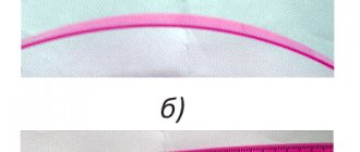
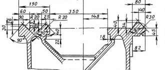
3. Processing of the control (reference) part. A comprehensive check of the accuracy of processing on a CNC machine is checking a reference part (standard) processed according to NC. In Fig. 9.21, and shows a drawing of a standard for comprehensive testing of the quality of adjustment of a multi-purpose CNC machine. For machines with a horizontal spindle, the standard can be made in the form of a square. For horizontal machines with a ratio of maximum movements along the X and Z axes of more than 1:6 and for vertical machines with the same ratio of maximum movements along the X and Y axes, it is recommended to use two standards. The standard is finally processed on the base surfaces with an accuracy twice the tolerances on the surfaces being tested.
In addition to a comprehensive check, it is necessary to check the accuracy of the center distances of the machined holes. To do this, according to the program, five holes of grade H7 are drilled and bored in the standard. The length of the holes must exceed or be equal to the diameter. It is possible to bore holes to check the center distances and on a standard for a comprehensive check. The test is carried out using a microscope or a device designed to measure center distances.
For horizontal machines, check the deviation from the alignment of holes processed by rotating the table. The measurement is performed twice, taking each of the bored holes as the base. The deviation from the alignment of the tested axes is equal to the largest of the obtained deviations.
In Fig. 9.21, b shows the standard for a CNC lathe. The part is processed in compliance with the technical parameters (cutting mode, material, geometry of cutting tools, coolant) recommended by the equipment manufacturer.
On CNC machines, tests for maximum loads are performed and cutting conditions are specified for characteristic types of processing and tools. When testing for maximum force of the main movement drive and feed drives, drilling with a tool of the largest diameter and milling with end mills are carried out.
Who does the adjustment
Setting up a CNC machine for processing is a complex task, which is carried out by qualified employees with technical training.
To successfully configure machine equipment, a control panel operator requires:
- professional knowledge of instrument design;
- ability to operate the device in different modes;
- ability to use technological equipment and other tools of a milling machine.
The responsibilities of the adjuster include programming and launching control systems, as well as checking the electronics and mechanics of the configured devices during operation. He must not only have theoretical knowledge of how to set up the device, but also have practical experience.
People with higher education in the field of:
- mechanical engineering;
- programming;
- electronics and computer technology.
Installers periodically need to undergo advanced training. This condition is required in connection with the periodic updating of machine-tool turning instruments, their modernization, as well as the release of new models.
What is a CNC machine setup map and why is it needed, who compiles it?
A CNC machine setup chart (CNC) is a calculation and technological map in which statistics on changes in the production process are displayed on a flat image (drawing) for visual perception of its main essence. It is the main document for the equipment operator when preparing it for a specific operation, as well as for the assembler and adjuster of the working tool when selecting it.
The KNS reflects the most important parameters: the required tool (main and auxiliary), its location on the machine and application; dimensional chain of the system at all stages of the work process; technological process modes; configuration of the final result indicating the main landmarks (reference points); executive dimensions.
The CNS is developed by the enterprise's technological service. The technologist enters into it the results of the final development of a specific technological operation. The graphically designed map is transferred to the CNC operator, who, after appropriate processing, enters it into the machine program. After entering, it becomes available to the operator, and he only needs to find the desired CNS if necessary to perform a certain operation. The machine will provide the operation without additional settings, according to previous data.
The use of CNS is quite justified. When performing different types of operations on one machine in different sequences, the need for adjustment at each transition is eliminated. The production of a part may stop for a long time, but subsequently there is a need to resume it. With KNS, there is no need to develop technical documentation again. It is enough to use the computer memory and remove the previously used card. Finally, when all service personnel are replaced, there is a need for new employees to master the entire product range. This will take time. If you have a CNS, you just need to launch it to set the required modes.
CNC operating modes
By adjusting the control program and software, the unit operator uses modes to adjust the operation of the machine tool. There are several modes that are used by the operator:
- input of information - implementation of a processing control program, its analysis, search and elimination of errors;
- automatic operation - the process of milling a part, adjusting actions, saving parameters;
- intervention by the installer - correction of settings, entering new information without using automatic control of milling machines;
- manual actions - creating a control program by manually processing the part and saving the necessary parameters;
- editing – elimination of unnecessary frames that impair the quality of detail processing;
- information output – transferring the downloaded program to removable media or another device via a network connection;
- calculation - obtaining the necessary parameters based on the use of formulas;
- using a display – displaying the processing of a part on the screen at the time of this task;
- diagnostics - checking the device, after which a warning about possible problems or a message about an emergency condition is displayed.
The peculiarity of the adjustment is that it cannot be performed professionally using just one mode. The operator must use several modes simultaneously or in stages to configure the machine tool to perform the required task.
Diomash Engineering (CAO)
Address : metro station Tsvetnoy Boulevard, Trubnaya St., 21 Website : https://www.diomash.ru Telephone Cost : from 22,000 rub. per course
Operator training is carried out by experienced specialists using modern equipment.
The training station consists of a PC and a machine control panel. Future specialists learn the intricacies of working with software, master the process of machine operation using training stands, and then practice their skills on a full-fledged machine.
Training is possible on the customer's premises. The main advantage of this approach is the possibility of conducting training directly on the equipment with which the operator will subsequently work. Consolidation of the acquired knowledge will be carried out using the example of a technological process of a specific enterprise.
By training as an operator or improving their qualifications, course participants will learn how to ensure technical reliability and optimize the operating operations of the machine. A professional approach to work and a deep understanding of production processes will help you avoid malfunctions.
Setup diagram
The setup is carried out step by step in several stages. The sequence of steps must not be changed, otherwise the task will be completed incorrectly. There are six main setup stages:
- installation of equipment in a fixed position;
- installation of devices and working mechanisms;
- performing dimensional adjustments;
- input of control program;
- processing of a test piece;
- assessing the performance of the control program and making corrections.
It should be borne in mind that even an experienced operator cannot adjust metal-cutting devices without the need to make changes. This process is called adjustment. It represents additional adjustment in order to improve the quality of processing. If the machine was set up by a professional, he will definitely carry out adjustments and look at the errors in detail.
Contents of the setup sheet for CNC machines
To fully understand the commands in the CNS, you need to enter the following information:
- model and brand of machine and control system;
- name of the final product and UE;
- a sketch of the product indicating the numbers of surfaces in order of their processing, location in relation to the working part of the machine;
- name and serial numbers of working tools;
- information on the devices necessary for installation on the machine for the operation;
- movement (overhang) of tools along the axes;
- sequence of operations;
- coordinates of the starting points of the working bodies and the coordinates of the start of processing.
Additionally, information about non-standard devices and mechanisms necessary for the work is entered. Information specific to a specific type of machine is entered into the CNS. The document must fully describe the system “machine - fixtures - tools - workpiece - finished product” at all stages of processing. The reference points clearly describe the configuration of the surface being processed.
Tool installation
The first stage of setup is the installation of tools. But you can start with installation only after cleaning the components from dust, chips and other contaminants. For this it is recommended to use:
- rags;
- tassels;
- toothbrush.
Then you need to place plugs in the slots and threaded holes that you do not plan to use. After this, you should make sure that the screws are in good condition. By tightening the jaws, you need to block the rotation of the chuck. This condition is ensured by a drive. The keys used to secure the equipment during installation must be in good condition.
Important! When adjusting, it is recommended to use tools to strengthen the clamp. They can overtighten it, causing it to become unusable.
Tool binding
At the second stage, the tool is linked. This task is one of the most important during setup performed by the operator. The smooth operation of the equipment depends on how correctly the theory was understood and whether errors were made during binding.
The binding is carried out by determining the movements of the X and Z axes along which the departures were recorded. For measurements, not only programs are used, but also calipers. It is recommended to use the Columbus model. Special sensors are also used to accurately determine overhangs. The estimated overhang values are entered into the table, after which it is easier to determine the expected trajectory of the working tool. If it is already configured, you can proceed to the next step.
Determination of workpiece zero
This value is determined after the milling machines are linked. It will indicate the surface area of the workpiece from which processing will begin. In most cases, the end part of the part is used. It has a physical surface that the tool can touch. If it does not reach the workpiece, you must select another zone. The machine will not move the cutter to the desired location automatically, so the operator must do this.
Important! You cannot start processing a part with idle movement.
To determine this value, two functions are provided in the numerical control system:
- the first is designed for one-time processing, and after turning off the machine’s CNC does not retain the value of zero;
- the second is intended for serial processing, and ensures that data is saved after the device is turned off.
Recommendations for working with technological documentation
Source: hgmakina.net
There are several options for the execution of technological documentation for setting up a CNC machine. The most extensive list consists of the following documents:
- Machine setup map;
- Operational sketches;
- Settlement and technological map;
- Operating mode map.
Such a list is necessary for large enterprises where various parts are produced. To work in small companies where several machines are used and the product range is small, you can introduce your own rules for drawing up documentation. The main thing is to adhere to the principle that the file cabinet used should be understandable to any new employee without long retraining and maintain efficiency when updating the product range.
Input and output of control programs
Input and output of a control program is one of the simplest actions when working with a CNC machine. To perform this task, you must connect the milling tool to the control device. It can be:
- desktop computer;
- control terminal;
- laptop.
If you are using a computer or laptop, you must first install the machine program on it. These actions are performed by pressing the corresponding keys. They may also be signed in English. Additionally, after selecting a task, you must press the “execute” button. Operations can only be performed when the milling machine is switched off.
These instructions are valid for machines with a plywood frame of the “Modelist” series, desktop aluminum machines, as well as medium-sized machines made of aluminum structural profiles with ball screw transmission.
Instructions for starting large rack and pinion machines can be found at the following link:
https://cncmodelist.ru/opisanie-stankov/tekhnicheskoe-opisanie-chpu-stankov/instruktsiya-po-pervomu-zapusku-stanka-2.html
STEP 1. Connecting the controller.
1.1 Connect the stepper motor controller to the machine according to the markings on the wires and the plate above the controller terminal blocks. Picture 1.
Figure 1. Connecting a stepper motor controller
1.2 Connect the stepper motor controller to the computer.
Figure 2 – connecting the stepper motor controller to the LPT port of the computer.
1.3 When using a USB-LPT adapter, make the connection according to Figures 3 and 4.
Recommended connection option Figure 3.
Figure 4
STEP 2. Preparing the spindle.
If a liquid cooling spindle is installed on the machine, assemble the cooling system according to the relevant instructions. Instructions are sent upon request by email.
STEP 3. Preparing the PC.
3.1 ATTENTION IMPORTANT! To control the machine directly via the LPT port, it is not possible to use computers with multi-core INTEL processors .
(Intell motherboards have a means of changing the operating frequency of the processor when the load on it changes. In this case, all ports also experience frequency fluctuations - as a result, the signal “floats”, that is, when Mach3 is running, the frequency of the step signal changes, which leads to uneven movement of the working body of the machine - jerking, impacts and even stops)
To check the LPT port, we move 3-4 times in manual movement mode (using the ← → and ↓↑ keys) to the full length of the desktop. The movement should occur smoothly at a constant speed, without jerking, jerking, hitting or stopping. If during movement there are local changes in the speed of movement and/or a stop during the movement of the portal, then to check it is necessary to change the Velocity parameter in the Config →MotorTuning menu item, reducing it by 10 times. If changes in movement speed decrease and stops stop, but the shocks and jolts continue, then this motherboard is not suitable for controlling the machine via the LPT port.
for working directly via LPT port :
A) only computers with single-core INTEL processors and any computers with an AMD processor and only 32-bit versions of the windows operating system
B) any computers with the LinuxCNC operating system.
3.2 When working with the machine via a USB adapter or Ethernet adapter, you can use any computer and any version of the Windows operating system. USB adapters should only be specialized ones, with a driver for the Mach3 program.
3.3 The computer for controlling the machine must be separately dedicated, without unnecessary programs. Do not install antiviruses! RAM at least 1 GB, if the video card is built-in then at least 1.5 GB, processor at least 1 GHz. Before installing mach3 reinstall the operating system , be sure to install all the drivers necessary for the system , disable the firewall , disable screen blanking in the power settings , disable screen savers , disable paging files from hard drives .
For more information about installing and configuring the software for machine operation, please read the information at the following link:
https://cncmodelist.ru/opisanie-stankov/tekhnicheskoe-opisanie-chpu-stankov/instruktsiya-po-ustanovke-programmnogo-obespecheniya.html
Disabling antivirus and firewall in Windows XP:
3.3.1 Go to Start Menu, open Control Panel.
3.3.2 Open Security Center.
3.3.3 Click Windows Firewall.
3.3.4 In the window that appears, change the switch to Disable (not recommended) and click OK.
3.3.5 To disable Windows security warnings, click in the Windows Security Center window the link Change How Security Center Notifies You. In the window that appears, uncheck all the boxes and then click OK.
Disabling antivirus and firewall in Windows 7:
3.3.6 To disable the firewall, you need to open it, to find it, use the Windows 7 search. Open the Start menu and write “bra” and select simple Windows firewall.
3.3.7 On the left side of the window, select Turn Windows Firewall on or off.
3.3.8 In the window that opens, you can disable the firewall for all networks at once.
3.3.9 Afterwards, you need to turn off the Windows Firewall service. Use search from the Start menu.
3.3.10 In the window that opens, find the Windows Firewall service and double-click on it with the left mouse button. In the Properties window that opens, click Stop. Then, in the Startup type field, select Disabled from the drop-down menu. Click OK.
3.3.11 Edit the system configuration. Open Start and type "con". Select System Configuration. In the window that opens, go to the Services tab, find Windows Firewall. Uncheck the box and click OK
STEP 4. Installation, checking the correct operation of the program that generates G-code.
4.1 Install Mach3 on your computer.
4.2 Copy to the Mach 3 folder located on the C drive: the machine profile (settings file), sent by email, transferred on a storage medium (flash drive) or downloaded from the website.
4.3 If you are using a USB-LPT adapter, install the drivers and plug-in according to the article Connecting a controller using a USB-LPT adapter or the instruction manual for the adapter.
4.4 When using a PCI-LPT expansion card, the procedure is also described in the article “Connecting a controller using a PCI LPT card.”
4.5 To launch the program you will need the “Mach3 Loader” shortcut; other shortcuts can be removed.
4.6 In the window that opens, Figure 5, select the machine profile and click OK.
Figure 5.
4.7 Select the control source, Figure 6 when working with an LPT port or Figure 7 when working with a USB-LPT adapter.
Figure 6.
Figure 7.
4.8 The main window of the Mach3 program loads, Figure 8.
Figure 8.
4.9 Turn on the power to the stepper motor controller. In the main window of the MACH3 program, press the “Reset” key (1) so that the frame around it does not blink and glows green, Figure 8. At this moment, the stepper motors should fix their position (a click will be heard) and make a slight noise. Now, by pressing the arrows on the keyboard (left, right, up, down), we observe movement along the axes on the machine, and on the screen, a change in coordinates in the XY fields at the top left, to move along the Z axis, the PageUP, PageDown buttons. You can also call up the on-screen movement control panel by pressing the “Tab” key on your computer keyboard, Figure 10.
Figure 10
4.10 If the movement does not occur, check that the program and drivers are installed correctly.
4.10.1 If you are using a connection via an LPT port, then open “Control Panel” - “Device Manager” - find Mach3 X Pulsing Engines properties. Correctly installed driver - Figure 12.
Figure 12
4.10.2 If you are using a USB-LPT adapter, then open “Control Panel” - “Device Manager” - find the CNCDevicesClass properties. Correct installation of drivers and correct detection of the adapter by the operating system – Figure 13.
Figure 13
4.11 If the direction of movement of the machine portal does not coincide with the direction of the keyboard arrows, for example, when pressing the “←” key the tool moves to the right, you can change the direction in the Config->Port and pins->Motor outputs menu by checking the DirLowActive field opposite the desired axis, Figure 14 .
Figure 14.
STEP 5 Checking the correct movement of the working tool.
To check the correct movement of the working tool, you need to place a ruler on the table and, using the keyboard to control the movement with arrows, check that the distance traveled on the ruler matches the readings in the MACH3 coordinate display windows.
5.1 Set the default units of measurement to millimeters: open Config->Select Native Units. Mach3 will display a window warning you that the units of measurement set in the program must match those used in the G-code. Click OK and go to the window for setting units of measurement, Figure 14.
5.2 For the settings to take effect, restart the program. If you no longer plan to use the inch measurement system when creating control G-codes, we leave the metric system for permanent use.
Below is an example of checking the settings for the Y axis. All axes should be checked in the same way.
5.3 Move the portal and the machine carriage all the way towards you and to the left - Figure 15.
5.4 Reset the readings of the digital fields with the coordinates of the portal position by pressing the Zero X, Zero Y, Zero Z buttons, set the ruler along the Y axis, Figure 16.
Figure 16.
5.5 Using the ↑ key, move the portal 100 mm along the coordinates of the digital field. Next, we check with the actual movement along the ruler - Figure 17.
Figure 17.
5.6 If the actual movement does not coincide with the coordinates in Mach3, we carry out calibration for the corresponding axis of movement, as described in the documentation of the Mach3 program.
5.7 Close Mach3 and turn off the power to the machine.
STEP 6. Installation of the cutter.
6.1 For machines using Kress spindles, key 17 is used to install the cutter. During installation, hold the shaft by pressing the lock button, Figure 18.
By rotating the nut counterclockwise, we release the collet, insert the cutter and clamp the cutter shank in the collet by rotating the nut clockwise. Installed cutter - Figure 19.
Figure 18.
Figure 19.
6.2 For machines using liquid-cooled spindles with an ER11 collet, the cutter is installed using keys 13 and 17, Figures 20..22. To install the cutter, hold the spindle shaft by the flat on the shaft with a wrench, release the collet clamping nut, insert the cutter, and clamp the cutter shank.
Figure 20.
Figure 21.
Figure 22.
STEP 7. Installation of the workpiece.
7.1 Installation of the workpiece on the machine’s work table from a profile with a T-slot is carried out with metal clamps - Figure 23.
Figure 23.
7.2 When using a machine with a plywood table or plywood sacrificial table:
7.2.1 The simplest mounting option is using “self-tapping” screws, Figure 24.
Figure 24.
7.2.2 There are also many options for fastening the workpiece using furniture bushings, Figures 25...30. More information about this mounting option in https://cncmodelist.ru/stati/eto-interesno/poleznye-prisposobleniya-dlya-stankov-s-chpu.html:
Figure 25. Furniture threaded bushing
Figure 26. Installed threaded bushings at the corners of the table
Figure 27. Installed clamps
Figure 28. Workpiece secured with clamps
Figure 29. Workpiece secured with standard steel machine clamps
Figure 30 Installation of additional strips for fastening workpieces of any size anywhere on the table
STEP 8. Installation of the working part of the machine at the starting point of cutting.
8.1 Turn on the power of the machine, launch Mach3 and move the machine carriage to the starting point of cutting (usually the lower left corner (you are facing the front of the machine)) using the arrows on the keyboard and the “PageUP” and “PageDown” buttons (or the virtual remote control control – called by the Tab button). The starting point for cutting is determined when creating a project - for example, a new model in ArtCam, Figure 31.
figure 31
8.2 If only G-code is available, then the starting point can be determined in the Mach3 window by loading the executable file: File→Load G-Code. We reset the readings of the digital fields with the coordinates of the portal position - by pressing the Zero X, Zero Y, Zero Z buttons, the cursor in the visualization window is set to the starting point.
Figure 32.
8.3 By controlling the vertical movement of the spindle, we touch the lower end of the cutter to the workpiece material. By pressing the Zero X, Zero Y, Zero Z buttons, we reset the program coordinates, Figures 33, 34.
Figure 33.
Figure 34
8.4 By pressing the “PgUp” button, raise the spindle to a safe height of -10...15mm above the workpiece.
STEP 9. Load the G-code: (File→Load G-Code). The machine is ready to start.
STEP 10. Start the spindle.
10.2 When working with a liquid cooling spindle, Figure 39: - start the liquid cooling system of the spindle (turn on the pump). — turn on the frequency converter. — by rotating the potentiometer on the front panel of the frequency converter, we set the required spindle rotation speed. — by pressing the RUN button we start the spindle.
Figure 39
10.3 Next, by clicking the “Cycle Start” button in the main window, we launch the executable G-code, Figure 40.
Figure 40.
11.Activation of limit switches
If limit sensors are installed on the machine, but not activated, then to enable limit sensors in the Mach3 program menu
config->Port and Pins->Input Signal check the boxes as shown in Figures 41 and 42
Figure 41. Activation of limit switches for machines with installed inductive sensors
Figure 42. Activation of limit switches for machines with installed mechanical sensors
Note. If base limit switches are installed on the machine, then the search for the zero point of the machine coordinates is carried out by pressing the “Ref All Home” button, Figure 43.
Figure 43.
If there are no limit switches, then when you press the “Ref All Home” button, the machine coordinates are reset. If there are no limit switches, then the settings for the “Home” inputs are presented in Figure 44.
Figure 44.
When working with the Modelist USB-LPT adapter in the absence of limit switches, the procedure for resetting machine coordinates is as follows: - use the ← and ↓ keys to set the machine carriage to the lower left corner. — use the key and PgUp to raise the spindle up until it stops. — press the “RESET” button on the main screen of Mach3. - remove the adapter cord from the USB port of the computer (do not forget to disconnect the device in the system before removing it, just like a regular flash drive) - on the main screen of Mach3, switch to displaying machine coordinates, for which press the “Machine Coord's” button, indicating that you are in the machine coordinates display mode, a red frame around the button will be indicated, Figure 45.
Figure 45.
— connect the adapter cord to the USB port and wait 10-15 seconds until Windows detects the adapter. -press the “RESET” button and the machine coordinates will be reset to zero. — go to the mode of displaying program coordinates, for which press the “Machine Coord's” button again, the red frame around the button should go out.
STEP 11. Maintenance of the machine.
Graphic control of the control program
This action is necessary if the control program was entered manually, or a large number of changes were made in the adjustment mode. A special key is also provided to enable graphic control.
This function allows you to monitor the movements of the router and record the configured path it is moving along. But she doesn't take correction into account. The processing process on the machines is displayed on the screen, where the operator can observe it. This feature allows you not only to monitor the operation of milling devices that operate intermittently, but also of serviceable instrumental devices. It allows you to minimize the likelihood of an error occurring.
Important! Before starting the function, you must enter the workpiece parameters and also set the value to zero. If this is not done, the machine may fail and require repair.
Development of a control program for CNC machines
To carry out the required operation on the machine, the UE must set the trajectory of the working tool. Calculated data is recorded on the medium using a specific sequence of phrases. Such phrases contain the necessary geometric and technological information that is necessary for processing a specific section of the workpiece.
The order of phrases must fully correspond to the sequence of implementation of technological techniques. All phrases include a certain number of sides of punched paper, and each of them corresponds to a record in the form of code symbols and signs. Several lines within a phrase with a certain sequence form a program for one working part of the machine. 2 options for recording UE can be used: with frames, i.e., a constant length of phrases, or with their length changing.
Automatic setup
The automatic mode assumes autonomous movement of the tool and control over it frame by frame. If you are milling continuously, you do not need to move the workpiece yourself, but you will need to watch for sounds. At the slightest change in the standard sound, you should press the power button. To do this, it is recommended to keep your hand on the power button when operating it. Otherwise, the workpiece will be damaged and the machine may break down.
The program does not have to be started from the very beginning. But it must begin with the tool change point. Most control programs do not have a restart function. The launch is performed on the computer or controller after selecting the desired frame.
Registration procedure
The registration of the CNC is carried out in the following sequence:
- In a conventional (rectangular) coordinate system, a sketch of the workpiece is drawn. The point from which processing begins (starting point) is marked.
- The location of fastening points (zones) on the machine is marked, taking into account the selected equipment.
- The trajectory of movement of the working tool in a given coordinate system is indicated.
- Reference points are set on the tool path with a digital designation and an indication of the direction of movement using arrows.
- Control points are marked at which a short-term stop of the machine is planned to check the correctness and accuracy of processing.
- At each processing site its modes are noted.
- In a special way, reference points are identified, the coordinates of which are determined directly from the CNS.
- Additional information is added to clarify the processing features - the sequence of operations, the characteristics of the tool, etc. You can use a digital or letter designation.
When developing a CNA, it is recommended to take into account the following nuances:
- It is advisable to combine working and idle operations.
- The most extensive and difficult operations are performed first.
- When processing products with complex configurations, finishing and roughing tools are used.
- During processing, rigidity may change, which must be taken into account when determining the order of operations.
- It is necessary to exclude collisions between the workpiece and the tool at idle speed.
Important! The design of the CNA is often done manually by the technologist. Currently, there are CAD/CAM systems that create a document automatically when you enter a program for processing a specific part.