Combined square
Alas, in most workshops this multifunctional tool is used only for drawing transverse lines on workpieces. The square block can be used separately from the ruler to set angles of 45° and 90° when adjusting the inclination of the disk on a saw machine, adjusting the cross stop or longitudinal stop of the jointer. By fixing the head relative to the ruler, you can measure the distance from the cutter to the longitudinal stop of the milling table (photo above) or the overhang of the saw blade. By placing the edge of the ruler against the longitudinal stop of the milling table, you can install the cutter bearing flush with the stop. The price of a combination square can be $15-75. (In general, the price reflects the reliability and accuracy of the tool.) We recommend the Starrett squares, model with a 305 mm ruler (photo above).
Configuring sensors.
On the Input Signals tab of the Config->Ports and Pins menu, you should specify which pins of which ports your sensors are connected to.
By analogy with the previous setting, Enable allows the program to use this sensor, Port# and Pin Number specify the port number and its pin, respectively, and Active Low specifies whether the input will be triggered when a low level (check mark) or high level (cross) appears on the contact. Emergency sensors for the extreme positions of the axes are written in the lines <AXLE>++ and <AXLE>—. Zero sensor - <AXIS> Home.
The Probe input is used for a sensor for determining the tool height and workpiece dimensions, EStop is an emergency stop button.
On the Output Signals tab of the Config->Ports and Pins menu, control signals are configured. Of these, the Enable group should be noted - permission to enable the driver of the corresponding axis. Note that if you want to use only one output to enable all drivers, for example, through a switching board, it is enough to configure only the Enable1 output.
Adjustable triangle
Widely spaced 0.5° graduations and a thin red indicator line make it easy to set the exact angle value.
The carpenter often has to deal with angles other than 90° and 45°. To be able to work with any angles, include an adjustable triangle in your toolbox. It can be purchased at craft stores for about $20.
Setting up pins
Now you need to indicate which port pins are used for what.
In the Config->Ports and Pins menu on the Motor Outputs tab, you must check the Enabled checkbox for each axis used, specify the pin numbers of your port for the corresponding signals in the Step Pin# and Dir Pin# columns, and specify the port numbers in the Step Port and Dir Port columns LPT (usually always 1).
If spindle control will be used (using PWM or via STEP/DIR), then it must also be configured on the Motor Outputs tab.
To generate PWM, the STEP signal from the Spindle line will be used
Long ruler rule
To detect gaps, place a light source behind the ruler. In this case, the jointer table must be raised from the side of the knife shaft.
Machine tables and their side extensions can sag, cast iron can warp, and moving machines around the workshop can also disrupt their settings. A ruler will help identify problems with surfaces that should be flat.
For such tasks, a long metal ruler is suitable, under the narrow edge of which all gaps and irregularities will be clearly visible. To allow the ruler to stand on the side edge, simply attach a spring clip called a clothespin to one end of the ruler. This will free your hands for machine setup operations. We found 1.2m and 1.5m rulers at large home improvement stores for $12-$15.
Formation of STEP/DIR by MACH3 program
First, let's look at how STEP/DIR pulses are generated by the MACH3 program. Any stepper driver takes a step when the STEP signal level changes from low to high or from high to low. This depends on the driver design or settings. The pulse generator in MACH3 is designed in such a way that the DIR signal changes almost simultaneously with the output of the active edge of the STEP signal. Obviously, the driver cannot react instantly to a change in the DIR signal, so if the delay after the DIR change before the STEP edge is insufficient, the driver may take a step in the wrong direction. The delay between the DIR change and the STEP edge in MACH3 cannot be more than 5 µs and is set by the Dir pulse parameter in the Motor Tuning window. A small delay value can cause a “skipped step” when changing the direction of the motor. Moreover, for some cheap drivers with slow optocouplers, even 5 μs may not be enough, but it is impossible to increase the delay using MACH3.
Hour indicator
When very small deviations need to be detected when setting up a machine, use a dial indicator that can show deviations down to 0.01 mm. This measuring instrument sometimes costs a lot, but even an inexpensive hour indicator is quite suitable for our tasks.
In order for the indicator to remain stationary during measurements, an appropriate device will be required. You can purchase one of the ready-made attachments, such as the Super Vag (first photo below), or make your own attachment for installing jointer knives (second photo below).
SIMPLE ADDITIONS WILL MAKE THE TIME INDICATOR WORK FOR YOU
Attach the hour indicator to a fixture that can slide along the miter gauge groove. By moving it in the groove, you can check whether the rip fence is truly parallel.
By comparing the measurements on the front table and the machine blades, you can ensure that they are all at the same height.
Operating modes of a CNC milling machine
The main indicators of the processing mode are the working feed and spindle speed. The choice of cutter and its parameters is determined based on several factors, for example, the quality of detailing and the size of the workpiece being processed. To increase detail, you need to reduce the size of the cutter.
Operating modes are changed based on the material being processed. The following modes exist:
- Entering information. The control program is transferred to the machine memory. After that, it is analyzed for errors. If they exist, they are eliminated.
- Automatic processing. The workpiece is processed with actions adjusted and parameters saved.
- Installer intervention. The specialist adjusts the settings and supplements the program.
- Manual actions. The control program is recorded from manual processing of the workpiece.
- Editing. Unnecessary actions are removed.
- Information output. The recorded program is output to an external drive.
- Computational part. Calculations are being carried out.
- Using the display. The processing of the part during the execution of the task is displayed on the screen.
- Diagnostics. The device is checked for possible errors and problems.
Settings cannot be performed correctly when using only one mode. The operator must use several at once to ensure the highest quality setting possible.
Installation plate
This perfectly straight, precisely machined insert is installed in place of a saw blade in a circular saw, radial console or miter saw. It provides a longer, flatter surface than a saw blade for checking runout and checking machine settings.
After installing the mounting plate instead of the saw blade, check the machine settings. The plate is perfectly flat from edge to edge.
WHEN AND HOW TO USE THE SIX MAJOR MACHINE SETUP TOOLS
Setup diagram
The last stage of setup consists of a frame-by-frame check of the operation of the device in automatic mode. If the processing is continuous, then there is no need to move the workpiece, but you need to monitor the sounds of work.
If changes in sound are heard, you should immediately turn off the equipment. Otherwise, either the workpiece will deteriorate or the machine will break down.
The automatic processing program does not have to be started from the very beginning. But this must be the moment of changing the instrument.
If problems are identified, the adjuster makes additional adjustments or starts the whole process all over again.
Setting up a CNC machine is not a very complicated procedure if you know how to do it. But it is better to seek help from a specialist in this matter.
- November 16, 2020
- 2169
↑ Photos
I’m posting for your consideration a few photos of what I managed to do over a couple of summer months. First test pancake. Milling cutter No. 1. Scary right? And if the rest is of the same quality)))
The first serious check for the machine. Dimensions 17 by 25 cm. Relief height 10 mm, time spent - 4 hours. Like the next job, this one was done with the same cutter No. 1. As you can see, the result is quite tolerable.
And here the cutter became dull, and the wood began to burn.
I tried what a cone engraver can do.
My sister asked me to cut out a dog for her. Roughing – cutter No. 2 3 mm, finishing cutter No. 3 3 mm. Relief 6 mm, processing time about 1.5 hours.
Signs for the house. The relief is 10 mm, but already concave because this significantly reduces processing time. Not the entire area is processed, but only the inscription. Processing time is about 2 hours, using cutter No. 5 (direct engraver).
My attempt to make a three-dimensional wooden photograph. I made a mistake in pairing the man and the tree, but overall, I think it turned out well. Roughing - straight cutter 3 mm, finishing with a conical cutter 2 mm. The relief is 5 mm, but I don’t remember the processing time.
Well, the largest model. The first test of the big milling cutter, which he endured with dignity. The height of the relief is 20 mm, dimensions are 45 by 30 cm. Processing time is about 5 hours. Roughing with a straight single-pass cutter of 8 mm, finishing with a conical cutter of 8 mm. To my surprise, the detailing turned out quite good for an 8mm cutter.
Finding zero on an axis
In the same Homing/Limits window, you can configure the search for zero: the Home Neg field is responsible for the direction of movement when searching for zero, and Home off specifies the coordinate that must be assigned to this axis when finding the sensor. Speed % - speed (in % of maximum) at which the “head” will move towards the sensor.
Limiting movement along an axis Software limitation of movements ('Soft Limits') is configured there, in Homing/Limits. To do this, in the Soft Max and Soft Min fields, you must specify the maximum permissible coordinates along the axes. Using the Soft Limits button in the main program window, you can enable or disable the Soft Limits mode.
Now we move on to starting the stepper motors - “twisting the axes”. To do this, go to the main page of Mach and press the “Tab” key on the left side of the computer keyboard, after which the “MPG MODE” manual control panel will pop up on the screen on the right. We turn on the power of the controller, then press the “RESET” button, while the nearby running line stops and noise should appear from the supply of voltage to the stepper motors. Then with the left mouse button we press alternately on the buttons of the X (+ -), Y (+ -), Z (+ -) axes of the manual control panel, and the stepper motors of these axes should begin to rotate.
Individual settings:
Changing the direction of rotation of the axes (reverse)
Go to the “Config” menu and click “Homing/Limits”. In the window that appears, opposite the desired axis in the “Reversed” column, change the sign to a bird or cross, then click “OK”.
Loading a program with G-codes and starting/stopping it. Go to the “File” menu and click “Load G-Code”. In the window that appears, select the desired program and click “Open”.
This program loads and the Mach window looks like this:
Next, we stop (if necessary) the creeping line with the “Reset” button and start the program with the “Cycle Start” button, stopping with the “Stop” button.
Installation of equipment
Result: The required tooling for the part is correctly installed on the CNC machine.
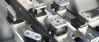
Vise
At this point we install any work support that will be used to hold our parts during processing. A large number of different mounts are available. Specifying exactly what is needed for a particular job is another important detail for a CNC setup sheet.
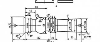
Tailstock control of a lathe
Fixing the tailstock of a lathe is done with a lever, and as the working stroke progresses, the clamping force increases. When processing heavy loads that require better fixation by the tailstock, the action on the lever must be vigorous. It is important not to confuse the resistance of the lever when clamping with its rigid stop at the end of the stroke. When the tailstock is used with minimal loads, its maximum fixation with the bed is not necessary. It is rational to measure the tailstock clamp with the upcoming load.
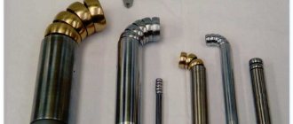
The tailstock quill is driven by manual feed by rotating the flywheel. The tools and accessories are secured in the quill cone in the following order:
- Checking the quill cones and tools for contamination;
- Inserting the outer cone into the quill cone and finding the position where the lock connector in the quill matches the tab on the tool cone (not required for tools that do not have a tab).
Toolholder control
The tool holder is a fairly precise mechanism that ensures rigidity of the tool attachment in specified positions. The correct position of the tool holder handle when clamped should correspond to the clockwise position at 3-4 o'clock. This position is ensured by the position of the spacer washer under the nut of the tool holder handle. The lever is clamped with an average elbow force. And pressing the handle cannot be done using your own weight to avoid weight loss. Squeezing the handle is done with one or more short pushes with the heel of the palm in a counterclockwise direction. Before rotating the tool holder, make sure there are no obstructions to the tool holder or the tool attached to it. Obstacles from the rotating elements of the machine pose a great danger.