Main technical indicators and advantages
Despite the fact that the presented model has been produced in Russia for more than 30 years, this does not prevent the machine from still creating good competition with more modern models. There are several reasons for this.
For example, the minimum deviation in the location of the treated surface and its shape is explained by the fact that the load-bearing elements have higher rigidity. Also, to increase rigidity, scraped guides with a compatible profile are used.
The spindle supports used by the vertical milling machine are equipped with paired angular contact and double-row roller bearings, which are characterized by increased load capacity. This facilitates power cutting with high quality processing. If standard lubrication is used, and the structural elements themselves have the correct tension, the bearing life will be longer than the amount of time before a major overhaul. To determine the class of bearings, you must read the technical data sheet.
In a screw pair, backlash is eliminated using a specially designed movable nut, which is included in the axial play control mechanism. Bimetallic materials are used in the production of all running nuts. Parts subject to more accelerated wear in areas of friction are produced using steel that is surface hardened with high-frequency heat. Exactly the same heat treatment method is used to strengthen gears. As a result, the equipment operates for a long period of time without the need for maintenance. And when the time comes to complete it, the cost of spare parts will be minimal.
The composition of a centralized effective lubrication system includes two groups. The first includes lubricant for the mechanisms in the console, and the second includes an oil supply system for the mechanisms located in the frame. Each of them, accordingly, provides separate power from its own plunger-type pump.
If the 6t12 1 machine is used every day in two shifts, the overhaul cycle will be at least 11 years. But achieving such performance is only possible if the user complies with operational requirements and primarily mills steel.
Increased drive power reserves, a wide range of speeds and feeds, minimal system compliance - all this contributes to high-performance processing of metal workpieces, which include plates made of STM or high-strength materials.
Achieving additional time savings is made possible thanks to the electromechanical method of fixing the tool. The table itself moves in automatic cycles. The revolutions are switched without sequential passage of steps.
Components
Considering the main characteristics, the basic design advantages of this equipment model are the presence of the following components:
- a device for slowing down the feed speed (the machine uses a proportional circuit);
- a mechanism to protect against metal shavings falling on the operator and others;
- an electromagnetic clutch that effectively brakes the spindle assembly in the horizontal plane;
- clutch to protect the main feed electric motor from overload;
- a device that allows you to adjust the gap in the screw pair (when feeding in the longitudinal direction).
What is 6T12 intended for?
The 6T12 cantilever milling machine is designed for milling all kinds of parts from various materials - steel, cast iron, non-ferrous metals... Thanks to the special design of the equipment, the 6T12 can be used to process both vertical and horizontal planes, as well as corners, frames, grooves, gears. If you retrofit the machine with a dividing head, a round rotary table, rotary cast-iron disks, and an auxiliary set of equipment with a cone, its technological capabilities will be expanded.
Location of components
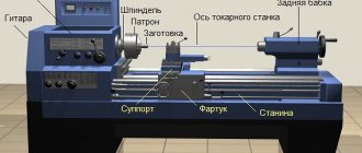
The image presented above shows the layout of all the components of the 6t12 machine. In total, the presented vertical machine used consists of the following components and assemblies.
- Coolant pump starting system.
- Control system for the direction in which the spindle rotates - right or left.
- Electric motor to drive the table.
- A dial whose surface has a scale indicating the feed amount.
- Mushroom for switching feed.
- Handle for moving the table manually and vertically.
- Flywheel for moving the table manually and in the transverse direction.
- The handle that presses the slide to the console.
- A handle designed to control the longitudinal movement of the table.
- Electric motor for spindle drive.
- Duplicate handle, including longitudinal movement of the table.
- Flywheel for moving the table manually and in the transverse direction.
- Cams for turning off the longitudinal table feed system in automatic mode.
- Coolant supply valve.
- Start button panel mounted on the front of the skid.
- Duplicate handle for turning on vertical or transverse transmission.
- Switch for the workspace lighting system.
- Switch for the entire machine.
- Handle for selecting spindle speed.
- A dial whose scale indicates the number of revolutions.
- Gearbox indicator.
- Start button panel on the spindle box.
- Cams that automatically turn off the vertical table feed.
- Cams that automatically turn off the cross feed of the table.
- Handle, including vertical and transverse feed of the table.
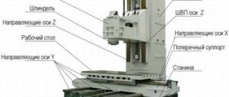
Location of controls
The layout of all control bodies is shown in the image above. It is worth noting that the design of the equipment in question is characterized by a convenient arrangement of buttons and other controls. This facilitates a quick transition to performing the required operations. Even a specialist with minimal practical experience, thanks to the comfortable placement of control elements, will be able to intuitively understand the main list of functions.
Part 1. Operating manual 6T13.000.000 RE.
- General information.
- Basic technical data and characteristics.
- Safety instructions.
- Composition of the machine.
- Design, operation of the machine and its components.
5.1. General view of the machine with the designation of controls.
5.2. List of controls.
5.3. Kinematic scheme.
5.4. List of kinematic diagrams.
5.5. Brief description of the assembly units of the machine.
- Lubrication system.
- Installation procedure.
7.1. Unpacking.
7.2. Transportation.
7.3. Installation and installation.
7.4. Preparation for initial start-up and initial start-up of the machine.
7.5. Operating procedure.
7.6. Regulation.
7.7. Tool cooling.
- Possible malfunctions and methods for eliminating them.
- Features of disassembly and assembly during repairs.
9.1. Dismantling and installing the slide on the console.
9.2. Dismantling and installation of the feed drive motor shaft.
9.3. Disassembling and assembling the gearbox.
9.4. Removing the vertical movement screw.
9.5. Features of replacing electromagnetic couplings during repairs.
How does the rotating head of the machine work?
The image above shows the current drawing of the rotary head, which is used in the 6T12 machine. It is centered in the annular recess located in the neck of the frame, secured with 4 bolts that fit into 1 different groove of the frame flange.
The spindle consists of a double-bearing shaft, which is integrated into the sliding sleeve. Adjusting the axial play comes down to the need to grind rings 4 and 3. Elimination of increased play in the front bearing becomes possible by tightening the nut and grinding ring 5. The owner is required to follow the correct maintenance procedure. To get rid of the radial play, the value of which is one hundredth of a millimeter, a grinding of approximately 0.12 millimeters is required.
Application and description of the 6T12 milling machine:
various milling operations on metal, vertical milling, at various angles. Operated in semi-automatic mode, the work table feeds are mechanical. The 6T12 machine has proven itself well in primary production at large machine-building enterprises. Accuracy class - N and P, according to GOST 8-82. The milling head performs vertical operations, can be rotated in both directions, for working at different angles. The productivity of the 6T12 milling machine can vary from single and small-scale, for example, in repair shops, to medium-scale, in industrial production, all movements of the table and tool are mechanized.
Kinematic diagram
The main task of the kinematic diagram is for the owner to understand how the main elements of the equipment interact and contact each other. The callouts include the number of gear teeth. The main movement is made possible by a flanged electric motor via an elastic coupling. The number of revolutions can be changed due to the movement of three gear blocks along special splined shafts.
The feeders are driven by a flanged electric motor mounted in the console. Thanks to two three-crown blocks and a movable gear, access to 18 different feeds is provided, which are transmitted to the console via a ball overload clutch.
Obtaining accelerated movements becomes possible when high-speed clutches are turned on, which rotates thanks to intermediate gears from an electric feed motor. The main element of the entire structure of the machine is the bed, on which other mechanisms and components are fixed. It is rigidly attached to the base using a set of pins.
Specifications
| Table size, mm | 300x1250 |
| Accuracy class (GOST 8-71, 8-82) | N |
| Longitudinal displacement (X axis), mm | 750 |
| Transverse movement (Y-axis), mm | 265 |
| Vertical movement (Z axis), mm | 410 |
| Load capacity, kg | 250/630 |
| Distance from the end of the spindle to the table, mm | 60-470 |
| Distance from the spindle axis to the vertical guides, mm | 152-322 |
| Number of feed speeds | 12/18 |
| Quill stroke, mm | 70 |
| Limit of longitudinal working feeds (X), mm/min | 15-800 |
| Transverse working feed limit (Y), mm/min | 15-800 |
| Limit of vertical working feeds (Z), mm/min | 6-270 |
| Accelerated longitudinal movement (X), mm/min | 2100 |
| Accelerated transverse movement (Y), mm/min | 2100 |
| Accelerated vertical movement (Z), mm/min | 800 |
| Spindle head rotation angle, degrees | ±45 |
| Cone on spindle | 7:42 NO 40 |
| Number of spindle speeds | 12/18 |
| Speed, rpm | 30-1600 |
| Main electric motor power, kW | 4/7,5 |
| Voltage, V | 380 |
| Current frequency, Hz | 50 |
| Overall dimensions, mm | |
| length | 1650 |
| width | 1540 |
| height | 1920 |
| Weight, kg | 1750/3250 |
Electrical diagram
A scan of the electrical circuit drawing is shown in the figure above. The equipment is optimized for operation in a three-phase network of 380 volts with alternating current frequency of 50 Hz. The control circuit operates at 110 volts AC. In control circuits, the current is constant; they operate at a voltage of 65 volts. To service local lighting, a voltage of 24 volts is supplied.
Main types of work of the vertical milling machine 6T12:
— vertical milling of flat, stepped, curved surfaces
— roughing and finishing operations, the rigidity of the structure allows you to install heavy parts without loss of accuracy and productivity
- milling and drilling work at various angles, due to tilting the head
— processing of grooves, wheels, horizontal surfaces of parts
— drilling, boring work, with automatic tool feed, through drilling and against the stop
— thread cutting in semi-automatic mode, fine tuning of feed.
Exploitation
To increase operating efficiency, each machine is equipped with a set of auxiliary circuits - bearings, slings, lubrication, kinematics, and so on. The rest of the manual includes electrical equipment. Here is a schematic diagram for connecting electrical appliances, as well as a set of specifications for selecting spare parts.
Based on statistical data obtained during the long-term production of the machine, the manufacturer has compiled a list of wearing parts. For them, a separate drawing of each element is provided. Thanks to unification, it becomes possible to use spare parts from other series of 6T machines, including 6T13.
Safety precautions
When performing work, it is necessary to adhere to general safety requirements. Each specialist must check the following working parts:
- grounding;
- correspondence of the voltage in the network with that used by the machine;
- checking the brake, signal and push-button devices for serviceability;
- checking the correct functioning of the locking device;
- checking the serviceability of the lubrication and cooling system;
- checking the condition of each hard stop that limits the movement of the calipers.
If any of the above elements are in poor technical condition, starting the electric motor is unacceptable. An initial diagnosis with further troubleshooting is required.
About the frame and console
Machines of any type are equipped with a basic unit in the form of a bed. The remaining working units and mechanisms are mounted on this surface. The bed is characterized by the following parameters:
- A large number of ribs.
- Trapezoidal section, developed.
- Highly reliable base.
The gearboxes are standard inside the frames. The turning head is inside the front parts. Installation is carried out using guides shaped like a circle. The console is placed on guides vertically. Characteristic is the separation of the main unit and the base. A bolted connection will allow you to secure the two components to each other.
When approaching from the right, access to the gearbox and pump is easy. To do this, use a window, usually closed with a special lining. The pump is used to supply lubricant to other internal parts. The speed controller opens on the left side. The base of the machines also has a special container where the cooling compound is placed. At the back of the base there is a hole through which liquid is drained if necessary.
Among the basic units is the console part of the machine. Thanks to this part, the transmission chain of various equipment is connected into one whole. It also participates in the distribution of movement into gears of various types. The feed motor is located at the bottom of the system. The movement through the gearbox goes to the cantilever gears.