Design features of the machine
The main purpose of the machine is milling the surfaces of workpieces with cutters of various shapes. The machine is designed for installation of shaped, cylindrical and finger cutting tools.
To increase processing accuracy, the design provides two types of feed: vertical and longitudinal. In addition to the milling function, a corner table with a horizontal surface can be installed on a table with a vertical working plane. Increased functionality is possible by installing additional components - a dividing head, a part clamp, etc.
Design features of the machine:
- bed made of cast iron. It helps reduce vibration levels, improves processing quality and maintenance-free operation time;
- chiseling function. To implement it, you need to purchase an additional device;
- the presence of two spindles - horizontal and vertical. Each of them has a wide range of parameters - rotation speed, feed, etc.;
- classic arrangement of components and controls. This contributes to minimal training time for personnel to operate this machine.
Another feature of the equipment is the vertical spindle head assembly. It is located on a flexible trunk, which allows you to process workpieces in hard-to-reach places.
The machine is used in small-scale production and for completing workshops. However, its installation in enterprises with mass production is currently impractical due to its outdated design and the impossibility of modernization.
Machine passport 676. Widely versatile milling machine
This instruction manual “Multiple universal milling tool machine 676” contains information necessary both for the maintenance personnel of this machine and for the employee directly involved in working on this machine.
This manual is an electronic version in PDF format of the original paper version. This documentation contains the Passport and Manual (instructions) for the operation of the universal milling machine 676. Purpose and scope of the machine Unpacking and transportation of the machine
- Unpacking and Shipping Instructions
- Machine transportation diagram
Machine foundation, installation, installation
- Machine installation instructions
- Installation drawing
Preparing the machine for initial start-up Machine passport
- General information, basic data
- Main dimensions and seats
- Control layout diagram
- Specification of control handles
- Kinematic diagram of the machine
- Specification of gears and worm wheels, worms, screws, nuts, chain sprockets
- Kinematic diagram of control mechanisms and accessories
- Specification of gears, worms, worms, screws, nuts, sprockets, racks, controls and accessories......
- Main movement mechanism
- Feed mechanism and kinematic calculation of table and horizontal headstock feeds
- Bearing layout
- Specification of rolling bearings
- Operating characteristics of the machine
- List of accessories and tools
Description of the machine
- General layout of the machine
- Brief description of machine angles
- General types of nodes
Machine electrical equipment passport
- Schematic diagram
- Wiring diagram
- General view of electrical equipment placement
- Description of the electrical circuit of the machine
- Electrical equipment specification
Machine lubrication
- Machine lubrication diagram
- Specification for the machine lubrication scheme
- Specification of lubrication points of accessories
- Instructions for servicing the lubrication system
Initial start-up of the machine Setting up the machine
Description of technical characteristics
The milling unit has its own unique technical parameters. It is recommended to read the equipment passport, which also contains operating rules and safety precautions.
Despite the cast iron frame, the assembled weight of the machine is only 900 kg. At the same time, its dimensions allow the unit to be installed in work areas with limited space. They do not exceed dimensions of 115*110*160 cm. Another feature is the presence of a main drive electric motor, which can operate in two power modes - 1.6 and 2.3 kW.
Technical characteristics of the OF-55 milling machine:
- table dimensions. Horizontal – 26*63 cm; vertical – 19.5*55 cm;
- distance from the end of the spindle to the table surface – 10.5 cm;
- distance of the spindle from the horizontal table – from 22 to 312 mm;
- maximum reach of the vertical spindle – 10 cm;
- maximum stroke indicators: transverse – 15 cm; longitudinal – 25 cm; vertical – 29 cm;
- spindle speed limits. Horizontal - from 42 to 2150 rpm; vertical - from 55 to 2450 rpm;
- number of speeds – 12;
- number of table feeds – 12
In addition to the main drive electric motor, the machine design has an auxiliary power unit to ensure the operation of the cooling system. Its power is 0.12 kW.
An example of working on a milling machine can be found in the video:
Kinematic diagram of the universal milling machine FS-250
Kinematic diagram of the universal milling machine FS-250
Description of the kinematic diagram of the FS-250 milling machine
The machine is driven by a two-speed electric motor type 4AM100 S6/4Y3 with a power of N=1.8/2.1 kW and a rotation speed of 1000/1500 rpm.
The movement from the electric motor is transmitted by a V-belt transmission to the gearbox receiving shaft and then in two directions:
- on horizontal and vertical spindle;
- on the feed box and the support carrying the vertical table.
Different 12 values of rotation speed of the horizontal and vertical spindles are obtained at the following gearbox positions:
- 4-5-7-2-1-8-9-16 ⇨ 42/72 rpm
- 3-6-7-2-1-8-9-16 ⇨ 112/170 rpm
- 1-8-9-16 (gear clutches 2-3 meshed) ⇨ 213/310 rpm
- 4-5-8-9-16 (gear clutches 7-8 meshed) ⇨ 310/4.80 rpm
- 3-6-8-9-16 (gear clutches 7-8 meshed) ⇨ 745/1130 rpm
- 2-7-8-9-16 (gear clutches 7-8 and 2-3 are meshed) ⇨ 1410/2150 rpm
The vertical spindle receives rotation from gears 16 of the horizontal spindle through gears 1 5, 14, 13. The movement to the feed box is carried out by a bushing-roller chain drive with a drive sprocket 47 sitting on the receiving shaft of the gearbox, and a receiving sprocket 46 of the input shaft of the feed box.
Various feeds “transmitted to the caliper and vertical table are obtained with the following positions of the gearbox gears:
- 45-43-44-40-42-37-35-34-33-32-20-19(18) ⇨ 10/15 mm/min
- 45-43-44-40-39-38-35-34-33-32-20-19(18) ⇨ 27/44 mm/min
- 45-43-42-37-35-34-33-32-20-19(18) ⇨ 37/55 mm/min
- 45-43-44-40-41-36-35-34-33-32-20-19(18) ⇨ 72/110 mm/min
- 45-43-42-39-38-35-34-33-32-20-19(18) ⇨ 100/150 mm/min
- 45-43-42-41-36-35-34-33-32-20-19(18) ⇨ 250/380 mm/min
When gear 18 is turned on, the feed direction changes.
The movement to the caliper is transmitted from the lead shaft to the lead screw 29 through gears 27-26 (in this case, the gear half-coupling 27 is engaged with the coupling half 48).
To move the caliper in the opposite direction, the movement from the drive roller is transmitted through gears 23-22-21 to the lead screw 29 (in this case, the gear half-coupling 23 is engaged with the coupling half 49).
Manual feeding of the vertical table is carried out by the caliper handwheel - handwheel 51, the headstock of the horizontal spindle - by handwheel 52.
The movement of the vertical spindle quill in the vertical head body is carried out with a special key and a square 53 roller - gear, which is meshed with the quill rack.
The feed mechanism is protected from damage by a ball-type safety device (gear half-coupling 34 and half-coupling 54) adjusted by a nut 55.
The safety clutch must ensure movement of the caliper with an installed horizontal table, loaded with a load of 800N, at an accelerated feed with alternately switched on working feeds of 10 and 380 mm/min.
Ensuring the reliability of the operation of the protective devices is determined by the fact that the safety clutch must operate when resistance to movement is created by a force of 50 N applied to the handle of the manual table feed handwheel in the vertical plane at a feed of 10 mm/min.
Description and design features
The unit is equipped with two mechanical feeds: longitudinal and vertical, and the transverse feed is manual. The vertical feed controls the movement of the caliper along the bed guides. Longitudinal feed moves the table along the slide guides.
A universal modification of the machine allows you to set the required angle to the surface being processed. The highly versatile machine has two spindle heads that can be rotated at different angles. The vertical milling machine is equipped with a vertical type shaft.
To work with large structures, a non-cantilever vertical design is used. The non-cantilever horizontal design is equipped with a table that moves along the guides of the frame.
Purpose and scope
The equipment can be used for a range of milling and boring operations with high accuracy parameters for machining parts. The following operations can be performed on the machine: drilling, reaming, chiselling, centering, milling, boring, reaming, countersinking.
For machine-building enterprises and small-scale production, this machine is indispensable in the manufacture of parts, planes, and tools. Due to the multi-level feed system, the machine is characterized by economical and precise processing of workpieces.
Specifications
Design features affect all main technical characteristics. The movable work table has T-shaped slots in which workpieces are fixed using clamps.
Dimensions and weight
Machine weight – 900 kg. The dimensions are such that this equipment can easily fit into a room of almost any size:
- length – 115 cm;
- width – 110 cm;
- height – 160 cm.
The vertical table has working surface dimensions of 550x195 mm.
Vertical spindle
The vertical spindle is designed for cutter shanks with Morse taper 4. The adjustable distance between the end and the table is 22–312 mm. Other technical characteristics of the vertical spindle:
- distance from the axis to the end – 100 mm;
- head rotation angle – 45°;
- the greatest movement along the axis is 60 mm.
Vertical spindle rotation speed – 56–2450 rpm.
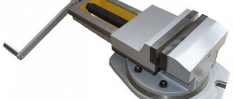
Vise
Vices also have their own technical characteristics depending on the design features:
- width x height of lips – 150 x 140 mm;
- the largest spread of the sponges is 50 mm;
- maximum rotation angle – 360°;
- scale division is 1 degree.
Spindle
Spindle Specifications:
- 12 speed levels;
- spindle speed – 42–2150 rpm;
- inner spindle housing – Morse 4;
- spindle movement per one revolution of the dial – 4 mm;
- one division of the dial is 0.025 mm.
In the horizontal plane, the maximum spindle movement is 150 mm.
Electrical equipment
The machine is powered by a three-phase alternating current source. Main drive speed – 1000/1500 rpm. Main drive power 1.6/2.3 kW. Coolant pump capacity – 22 l/min.
Electrical diagram
Kinetic scheme
Horizontal spindle and vertical head spindle
The versatility of the OF-55 machine is ensured by the ability to mount different heads - horizontal, standard vertical, high-speed vertical and grinding. All heads can be retracted back and forth along the support column to provide the required feed rate. The work table is attached to a flat vertical surface having T-shaped slots and providing for vertical and horizontal feeding. The rotation speed of the spindles is determined by the characteristics of the gearbox.
Main parameters:
- Distance from the end of the spindle to the table plane, mm – 105.
- Reach, mm – 100.
- The limits for adjusting the distance to a horizontal table are 25...312 mm.
- Spindle stroke in the following directions, mm: vertical – 290, longitudinal – 250, transverse – 150.
- Rotational speed of the horizontal spindle, min-1 – 42…1250.
- Rotational speed of the vertical spindle, min-1 – 56…2450.
The speed change is stepwise, by switching pairs of gears (a total of 12 speeds are available). The torque value can be changed by switching the rotation speed of the main drive motor.
Operating principle of the machine, passport
The massive cast iron bed absorbs vibration, which allows you to maintain the quality of the processed parts on this equipment. A wide range of feeds and spindle speeds, as well as the presence of mechanical feeds, ensure economical processing of workpieces in optimal conditions. The presence of two spindles gives a large number of possibilities when working on this machine, as well as extended additional accessories.
The small dimensions of the machine allow it to be placed in almost any room. For increased precision and quality of processing, the machine should be located away from sources of heat and vibration. The passport of the milling machine can be downloaded for free from the link - Passport of the special tool milling machine OF-55.
Maintenance and repair work
The most important part of preventative repair work is maintenance. It consists of regularly inspecting the main components of the machine, checking their performance and lubrication.
Electrical equipment, like other machine components, gradually wears out both physically and mentally. But most machine components can be easily replaced with similar ones, which significantly extends the service life of the equipment and increases the operating parameters of the machine. During operation, the machine must be grounded and for normal operation it must be operated in a room with a humidity of 65% and a temperature of 20 °C.
Warranty and repair
The factory warranty for this equipment is 1 year. The unit itself must undergo regular inspection and diagnostics, especially during prolonged and continuous operation. The most common breakdowns:
- drilling and driving on the table surface;
- the machine does not turn on;
- The network indicator does not work;
- spindle assembly bulkhead;
- collet wear;
- spindle cone wear;
- the center of the spindle is knocked down;
- the spindle does not rotate or rotates slowly;
- sudden interruption of work;
- release of the collet during operation.
During major and restoration repairs, the following work is carried out:
- disassembling the machine with washing and wiping all parts;
- replacement of bearings in electric motors;
- replacing drive belts;
- replacement of worn parts, gears, bearings;
- lubrication of all moving structural elements;
- Overhaul of cooling system pumps.
After repair, the machine must be checked at idle speed, noise, heating and processing accuracy must be checked. When checking the functionality of the machine, a test part is made.
The 6T12 cantilever milling machine refers to equipment that is designed to work with parts made of cast iron, steel, and various alloys. The unit is reliable and rigid, and is a continuation of similar units of the P series.
Used in single and serial production for various industries. The machine is unified and is capable of operating in three modes: automatic, jog and manual. The main advantage for industry is the high productivity and long service life of this equipment.
Reviews
The widely-universal milling machine OF-55 has long gained popularity at enterprises in the mechanical engineering industry. This equipment, according to the owners, is distinguished by its reliability, wide functionality, as well as the accuracy and quality of processing workpieces made of ferrous and non-ferrous metal. Also, all owners note the classic version of controlling this machine, which allows even a beginner to quickly master it. The machine itself was made according to a German analogue, but has been in demand at domestic enterprises for more than 30 years and is one of the most reliable and proven equipment.
The highly versatile OF-55 machine is considered one of the most proven types of equipment. An increased class of accuracy and expanded functionality make it possible to perform a number of specific operations on such equipment, including chiselling.
Milling machine OF 55
Developed industrial production requires the creation of a large machine park. Particular attention is paid to metalworking units that perform high-precision operations. In the USSR, such equipment was mainly purchased abroad. However, a number of factories produced domestic products that competed with foreign models. Noteworthy is the OF 55 milling machine.
Purpose and description of the machine
The design and manufacture of the OF 55 model was carried out by a machine tool manufacturer in the city of Vladimir, which began its activities in 1935. His design bureau developed and launched into production in 1967 the OF 55 milling machine, the technical characteristics of which were at a high level and made it possible to produce high-precision products. This year can be considered the year of release. The model has not been produced for a long time, but its high quality allows them to still be used in enterprises.
This unit is a cantilever-milling type machine. It is highly versatile and designed to process parts with high precision. The milling machine model OF 55 can process workpieces with cutters of different configurations using two spindles. The unit can perform longitudinal and vertical mechanical feeds, in addition, transverse movement can be carried out manually.
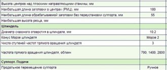
All information about the purpose, installation, maintenance and operation of the product can be obtained by reading the operating manual for the OF 55 milling machine. The table shows selected technical characteristics:
A complete list of data, as well as a kinematic diagram with a description and delivery set for the OF 55 milling machine is given in the passport included in the manual. In the documentation you can find an electrical diagram and a map of OF 55 bearings, which will be required when servicing the equipment.
Download the passport (operating instructions) of the OF-55 machine
Deciphering the name of the machine is difficult due to the difference from the standard marking. Unlike mass-produced models, specialized units include letters in the abbreviation that are assigned by the manufacturer. The numbers indicate the main operational parameter, in our case the width of the table in centimeters.
Milling equipment
The industry produces metal-cutting units, which are divided into nine groups. The sixth group includes machines that perform milling operations. They can machine surfaces, various grooves, grooves, gears, splines and much more. The instruction manual contains more information.
The machines are distinguished by their design features:
- continuously operating;
- console;
- non-console.
According to the operations performed, the equipment can be divided into:
- specialized;
- general purpose.
Each type has distinctive features, the description of which is contained in the product passport. All mechanisms are characterized by the movement of the cutter and feed, and the feed can relate to the workpiece or the cutter. The value of such a parameter as the size of the table also matters. To simplify the maintenance of the units, they are unified.
Sectional view of the OF-55 machine
The largest part of the equipment used is cantilever-milling models. The console, which provides a number of advantages during milling, reduces rigidity at the junction with the frame. To avoid this, increase the length of the console guides. For repair and tool areas, the production of widely universal machines has been established, their purpose is a small series or single production. The units have the ability to work with the part manually using a feed screw.
It should be remembered that the operating instructions must be carefully studied before starting work.
Machine Features
It is worth noting here the frame, the hollow base of which is a coolant tank. The upper part is used to install a gearbox capable of transmitting 12 speeds to the spindles. A feed box for the table is mounted at the bottom of the frame; it communicates 12 different feeds to it. A special compartment contains the electrical circuit of the OF milling machine.
The movement of the part, longitudinal and vertical, is carried out using a caliper. For manual movement, an OF 55 feed screw is used, if the movement is mechanical, a gearbox is used. The feed is regulated by handles, shutdown occurs using the end stops. When performing precise work, measuring tiles and an indicator are used, they are installed in special clamps. Over the years of production of the OF 55 milling machine, several upgrades have been made.
Convenience during work is achieved by using two spindles, and the vertical one can change the angle of inclination. This is achieved due to its location on the trunk, which extends. Optimal processing conditions for parts are achieved due to the ability to change spindle speeds over a wide range.
During continuous operation, it is necessary to monitor the lubrication of the bearings; this information is provided by the lubrication card. Lubrication will be required periodically:
- immediate;
- crankcase;
- automatic.
The following operational advantages can be noted:
- simple controls;
- compact dimensions;
- absorption of vibration by a heavy base;
- the ability to perform chiselling.
Getting spare parts for OF 55 milling machines is not a problem. However, its use in individual farming is difficult. Experts, in their articles, claim that the model has excellent characteristics, but is very heavy and expensive.
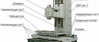
General layout of the wide-universal milling machine 67K25
A tool wide-universal milling machine consists of separate assembly units. A rack is attached to a cast iron base, where all the main components of the machine are mounted. The milling head moves along the horizontal guides of the rack, to which are attached: a vertical head, a trunk, a gearbox and a control panel. The caliper moves along the vertical guides of the rack, and the slide moves along its horizontal guides.
The feed motor is attached to the bottom of the rack.
To expand the technological capabilities of the machine, a large number of accessories are attached to it.
A corner or universal table is attached to the vertical base plane of the slide, which is used for installing the workpieces.
For dividing work, a round table and a dividing head are used, which can be installed either on a corner table or on a vertical plane of a slide.
For slotting work, a slotting head is designed, which is mounted on the milling head.
The high-speed head has its own drive and is also attached to the milling head.
The tool is mounted in the cones of the spindles. The tool clamping in the milling and vertical heads is mechanized.
Gearbox
The gearbox is assembled in a special housing 4.
The body is attached with a flange to the end of the milling head, and with flange 9 the box fits into the centering hole of the head. The gearbox consists of four shafts and blocks of gears, the movement of which allows the spindle to provide eighteen different speeds. Speed switching is carried out by a switching mechanism.
To change the speed, gear shift knob 2 must be lowered down. In this case, discs 10 and 12 are moved apart under the action of spring II. When turning the speed dial 3 and the associated disks, the position of the disk holes relative to the fingers 13 changes, thereby preparing for changing speeds. Then, using shift handle 2, the discs are brought to their original position. Then the fingers 13, moving, using levers, will move the gearbox gear blocks. When switching, it is possible that the ends of the teeth of the meshed gears will coincide and the discs will not align. In this case, you need to press the “Push” button on the remote control.
When switching speeds (when retracting the disks), rotation automatically stops.
Cylinder 5, disc springs 6, pipe 7 and cleaning rod 8 are provided for mechanized clamping of the tool. Clamping is carried out by disc springs b, and pressing is carried out by hydraulic cylinder 5 when the hydraulics are turned on.
Milling head
The milling head (Fig. 6.6) is equipped with rectangular guides and moves along the horizontal guides of the rack. A horizontal spindle is mounted in the front part of the headstock, which is driven into rotation by a gearbox secured by a flange at the rear of the headstock. A bracket 2 is attached to the end of the headstock, in the lower part of which a lead screw 5 is fixed, which ensures the transverse movement of the headstock. The main drive with a motor 4 and a poly-V-ribbed transmission is attached to the bracket 2, which transmits rotation to the gearbox with a rigid coupling 3. The tension of the poly-V-belt 7 is adjusted by moving the housing 8 using a screw 9. The trunk I moves along the upper guides of the headstock with support 6, which serves for horizontal milling mandrels.
Spindle horizontal
Spindle I is mounted in the milling head housing and receives rotation from the gearbox. The front and rear spindle supports are a double-row roller bearing with a tapered hole 2 and 4. Axial loads are carried by thrust bearings 3.
Machine support
The support serves for longitudinal and vertical movement of the main table mechanically or manually. The mechanical feed of the table is carried out by lead screws I and 16, which receive rotation when the clutches are engaged, from the drive shaft 2. The table is moved manually from the flywheel 12, and the support from the flywheel II. Flywheel II is mounted in bracket 10, which rotates on axis 9 relative to the fixed bracket 8 and can be installed in a convenient working position.
The movement of the caliper is controlled by a ruler and a dial with a division value of 0.02 mm.
Rack
The stand 17 is installed on the base 12 and is a box-section casting on which the main components of the machine are located, connected to each other by kinematic links. At the rear lower part of the rack on the plate 15 there is a motor 14, the rotation from which is transmitted to the shaft 6 through a gear pair 13-16, shaft 7, coupling II and a conical pair 9-8. When the electromagnetic clutch 4 is turned on, through a conical pair 1-2 to the pipe 18 with nuts 19 and 20. Flywheel 21 is used to manually move the milling head.
Main characteristics
The designs of the OF-55, as well as its characteristics, are varied and are divided into several categories:
- Console machines are equipped with a support console on which the mechanism table is located.
- Non-cantilever units, where a surface is located on a static frame that can move longitudinally and transversely.
- Continuous rotation drum units.
Features of the models
For a horizontal console modification, moving the console along the rack guides is one of the main movements. There is a table and a slide on it. The unit is equipped with a horizontal shaft and a retractable trunk.
The universal modification allows you to set the surface to the required angle.
The highly versatile machine is equipped with a spindle head that can rotate in two directions. This allows you to install the cutter at the required angle to the working area and the workpiece.
The OF 55 vertical milling machine is equipped with a vertical shaft installed in a rotating head attached to a stand.
The cantileverless vertical design is designed for working with large workpieces. The area moves along a customizable bed. The spindle head moves along the orientation of the rack.
The horizontal console-less unit is also equipped with a table that runs along the guides of the frame and a spindle head that moves along the guides of the rack.
Longitudinal milling structures are used for processing large-sized workpieces. A crossbar on which the milling heads are mounted is fixed to the vertically positioned racks. During operation, the table moves along the orientation of the racks.
Rotary milling units are equipped with end mills, which are required for primary and finishing processing of workpieces. The table rotates continuously according to the bed settings. The spindle head runs along the guides of the rack.
On a drum-milling tool, the part is mounted on a drum, which performs rotational movements. The heads move along the aiming posts.
The installation passport contains a detailed description of each modification, tool and accessories included in the kit.
Characteristics of CNC Milling Machines
Milling machines are a whole group of equipment for processing various materials.
- Universal
- Horizontal milling console
- Widely versatile
- Vertical milling
- Consoleless
- With mobile portal
- Copying
- Rotary milling
- Drum milling
Each type of machine has its own specifics, used for specific tasks and materials. In theory, any type of machine can be equipped with a CNC system, but we will consider the most popular type of this equipment - portal. Portal CNC machines are three-, four- and five-axis, without an automatic tool change system; with linear, drum and carousel automatic tool changing system. Also, one of the important types of machine equipment is the type of table; it comes with a T-slot or a vacuum clamp.
Application of the OF-55 milling unit of a wide-universal modification
The German FP-1 device is a prototype of the OF-55. Like its predecessor, OF 55 is used for milling workpieces. When servicing with a horizontal spindle, cylindrical, shaped or disk cutters are used. The vertical spindle can be set to the desired angle. End mills, keyed and end mills are used here.
The design is equipped with two mechanical feeds: longitudinal and transverse. The first moves the surface along the caliper reference. The second feed sets the movement of the support along the bed guides.
The electric motor provides operation in two modes: 1 thousand rpm and 1.5 thousand rpm.
For translational movement of the table and operation of the spindle, the machine is equipped with 12 speeds. This ensures high-quality processing of the part. Depending on the required result, the workpiece can be placed on the main table, corner or universal. Workpieces that require division are placed on a round table or processed using a dividing head.
The machine kit includes a convenient cabinet with tools and other accessories. For an additional fee, you can purchase accessories that expand the functionality of the unit.
Functionality
The location of vibrating and heat sources near a structure can negatively affect the accuracy of its operation. The characteristics of the OF-55 allow it to perform the following functions:
For machine-building enterprises and other mechanical production, the presence of additional devices for the OF-55 makes it highly versatile and indispensable in the manufacture of tools, parts, planes and other products. The model data sheet indicates the possibility of such an improvement.
The OF 55 milling machine is distinguished by economical processing of parts, thanks to the multi-level rotation of feeds and spindles. Most often, the unit is used in tool and mechanical shops of machine-building industries.
Basic technical data and characteristics of the GF2171S5 machine
| Parameter name | GF2171s5 | GF2171s6 |
| Main settings | ||
| Accuracy class according to GOST 8-82 | N | N/A |
| CNC device model | 2S45-65 | 2S45-65 |
| Number of controlled coordinates | 3 | 3 |
| Number of simultaneously controlled coordinates for linear/circular interpolation | 3/2 | 3/2 |
| The smallest and largest distance from the end of the spindle to the table, mm | 250..500 | 250..500 |
| Distance from the spindle axis to the vertical guides of the bed (overhang), mm | 500 | 500 |
| Limit dimensions of processed surfaces (length x width x height), mm | 850 x 250 x 380 | 950 x 350 x 400 |
| Maximum load on the table (center), kg | 400 | 400 |
| Desktop | ||
| Dimensions of the working surface of the table (length x width), mm | 1600 x 400 | 1600 x 400 |
| Number of T-slots Dimensions of T-slots | 3 | 3 |
| Maximum longitudinal movement of the table (X), mm | 1010 | 1010 |
| Maximum lateral movement of the table (Y), mm | 400 | 400 |
| Maximum vertical movement of the table (installation) (Z), mm | 250 | 250 |
| Maximum slider movement (Z), mm | 260 | 260 |
| Limit of working feeds of table and slider, mm/min | 3..6000 | 3..6000 |
| Speed of rapid movements of the table (X, Y) / slider (Z), mm/min | 7000 | 9000/ 7000 |
| Permissible feed force in X and Y coordinates, N | 15690 | 15690 |
| Permissible feed force along the Z coordinate, N | 9806 | 9806 |
| Positioning accuracy, mm | 0,015 | |
| Spindle | ||
| Spindle rotation speed, rpm (number of steps) | 50..2500 (12) | 50..2500 (12) |
| Number of spindle speeds | 18 | 18 |
| Maximum torque, kNm | 0,615 | 0,615 |
| Coefficient of spindle output speed range | 1,26 | 1,26 |
| Sketch of the spindle end according to GOST 24644-81 7:24 | 50 | 50 |
| Tool store | ||
| Tool magazine capacity | 12 | 12 |
| Tool change time, s | 20 | 20 |
| Maximum diameter of end mill, mm | 125 | |
| Maximum diameter of end mill, mm | 40 | |
| Maximum drill diameter, mm | 30 | |
| Maximum tool weight, kg | 15 | |
| Tool overhang from the end of the spindle, mm, no more | 250 | 250 |
| Electrical equipment and drive | ||
| Main motion drive electric motor, kW (rpm) | 7,5 (1450) | 11 (1466) |
| Feed drive electric motors HG-112B, HG-112C (X, Y axes), Nm | 17 | 23 |
| Electric motors for driving the slider feed HG-112C (Z axis), Nm | 23 | 23 |
| Electric motor for adjustment movement of the console, kW (rpm) | 2,2 (1450) | 2,2 (1410) |
| Electric motor of hydraulic station, kW (rpm) | 2,2 (1450) | 2,2 (1400) |
| Lubrication pump electric motor, kW (rpm) | 0,27 (1500) | 0,27 (1400) |
| Electric coolant pump Power, kW | 0,12 (2800 | 0,12 (2800) |
| Coolant pump capacity, l/min | 8 | |
| Type of hydraulic station | 5AG48-22N | 10-2, 2G48-1 |
| Dimensions and weight of the machine | ||
| Machine dimensions (length width height), mm | 3680 x 4170 x 3150 | 3660 x 4200 x 2850 |
| Machine weight, kg | 6580 | 6500 |
Bibliography:
Vertical cantilever milling machine with CNC and automatic tool change, model GF2171. Operating manual GF2171S5.000.000 RE Part 1, 1989 Vertical cantilever milling machine with CNC and automatic tool change, model GF2171. Operating manual for electrical equipment GF2171S5.000.000-02 RE1 Part 2, 1989
Avrutin S.V. Fundamentals of Milling, 1962
Avrutin S.V. Milling, 1963
Acherkan N.S. Metal-cutting machines, Volume 1, 1965
Barbashov F.A. Milling business 1973, p.141
Barbashov F.A. Milling work (Vocational education), 1986
Blumberg V.A. Milling machine handbook, 1984
Grigoriev S.P. Practice of coordinate boring and milling work, 1980
Kopylov R.B. Working on milling machines, 1971
Kosovsky V.L. Handbook of a young milling operator, 1992, p. 180
Kuvshinsky V.V. Milling, 1977
Nichkov A.G. Milling machines (Machinist's Library), 1977
Pikus M.Yu. A mechanic's guide to repairing metal-cutting machines, 1987
Plotitsyn V.G. Calculations of settings and adjustments of milling machines, 1969
Plotitsyn V.G. Setting up milling machines, 1975
Ryabov S.A. Modern milling machines and their equipment, 2006
Skhirtladze A.G., Novikov V.Yu. Technological equipment for machine-building industries, 1980
Tepinkichiev V.K. Metal cutting machines, 1973
Chernov N.N. Metal cutting machines, 1988
Frenkel S.Sh. Handbook of a young milling operator (3rd ed.) (Vocational education), 1978
Related Links
Home About the company News Articles Price list Contacts Reference information Download passport Interesting video KPO woodworking machines Manufacturers
Advantages
The model in question has several advantages:
- The cast bed eliminates vibration from the working area, which ensures high-quality processing of parts.
- Slotting operations. After installing additional devices on the machine, you can perform chiselling.
- Small dimensions allow it to be installed in almost any room.
- Classic controls ensure quick mastery of the unit.
12 spindle speeds allow you to choose the most suitable maintenance mode.