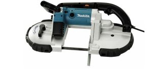
The creasing machine is used in tin work for joining cylindrical parts, flanging edges and rolling ribs. This is a mandatory stage in the processing of sheet metal products, so the characteristics of crimping must be approached carefully. The executive tool of the zig machine is rolling rollers of various profiles. Each type of roller is designed to perform a specific job. In production, the machine works in conjunction with a folding bender, a guillotine, folding equipment and rollers.
Classification and design solutions of beading machines
Such equipment (often also called zigmachines) is distinguished by the following characteristics:
- By drive type. Zigmachines are available with electric drive and manual drive.
- According to the number of pairs of rollers for zigmachines – two (IV2714, IV2716) and four.
- According to the control method - with a pedal or using a push-button station.
- According to the power and thickness of the metal being processed. On manual machines (for example, on a manual beveling machine model Stalex RM08), it is impossible to crimp workpieces thicker than 1...1.2 mm, while on driven equipment processing of steel and greater thickness is carried out - up to 4 mm.
- By the presence or absence of a drive reversing unit on the crimping machine (in the first case, you can perform calibrating creasing of the relief, which is often required when processing products made from high-carbon steels). Such possibilities are specified in the passport.
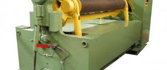
The most popular models of electrically driven zigging machines are two-roller machines of the IVA 27_ _ series with horizontal spindles. Electromechanical beading machines are manufactured in accordance with the technical specifications TU 2-041-94, and include the following components:
- drive motor;
- two-stage rm type gearbox;
- support shaft;
- intermediate gear;
- a pneumatic cylinder (or hydraulic cylinder) that controls the movement of the upper working roller;
- lever drive of the pressure shaft;
- pairs of rollers;
- stop mechanism (for creasing piece workpieces);
- feed unit.
- control systems (pedal, button).
Zig machine design
An electromechanical piping machine works like this. When the engine is turned on, the torque is transmitted through a reduction gearbox and an intermediate gear to the lower support roller, onto which the workpiece, which has previously passed through the straightening unit, is fed until it stops. When the lever system with pneumatic clamping of the equipment is turned on, the latter is fed until it comes into contact with the surface of the workpiece, after which the stop is folded back and the motion sensor turns on the power supply of the strip into the adjusted gap. The relief corresponding to the profile of the tool is formed. If it is necessary to calibrate the resulting profile, the rotation of the engine is reversed, or re-beading is performed, slightly reducing the value of the working gap. To remove the finished product from the working space of the zig machine, it is enough to return the tool to its upper position by turning the cylinder into reverse.
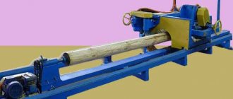
The IV2716 creasing machine can operate as part of a profiling production line; it operates in automatic mode, and a tape or a long strip of metal is used as the initial workpiece.
To facilitate removal of the finished part, the machine is additionally equipped with either a roll winder or swinging reset levers, which are controlled by cams installed at the free end of the support shaft. Standard sizes of serial electric beading machines
| Model | Maximum thickness of processed metal, mm | Bed reach, mm | Maximum zigovka speed, m/s | Minimum quilling speed, m/s | Total drive power, kW | Additional features |
| IV 2714 | 2,5 | 400 | 0,283 | 0,045 | 4,35 | Roller conveyor, device for circular cutting |
| IV 2716 | 4,0 | 500 | 0,283 | 0,055 | 5,3 |
Homemade electric profile bender
The electric profile bender, available for self-production, is the same manual design, the difference being the presence of an electric drive for rotating the rollers. It is necessary to make one of the support rollers drive by installing a gear gear on it. It meshes with the corresponding gear of the reduction gearbox, which is connected by a belt drive to the electric motor. In a similar way, you can make a profile bending machine as a whole, or modify the existing manual version of the design.
Required tools and materials
To make an electric pipe bender, you will need the same materials and tools that are listed above. In addition to them you will need:
- reduction gear;
- electric motor with a rotation speed of about 100 rpm;
- tensioner for the belt drive (can be combined with a landing platform for the engine).
It will not be possible to make either the engine or the gearbox yourself, so you will have to purchase them ready-made.
Dimensions and drawings
The size of a profile bender with an electric drive is no different from the size of a manual installation. The only design changes are the platform for the gearbox and the landing tension platform for the electric motor. They can be installed on the frame from the inside or outside, which is determined during the design process or during assembly if an existing machine is being modernized. There is no fundamental difference in design; additional elements are installed on a free area inside the frame.
Step-by-step manufacturing instructions
The procedure for assembling profile benders with an electric drive is practically no different from the already discussed technology for creating a manual machine.
The difference is the installation of the gearbox and electric motor.
Both units are mounted on the lower part of the frame and kinematically connected in accordance with the design features.
If a motor-gearbox assembly is used, which is structurally designed as a single unit, the master’s task will only be to fix it in a certain position and connect the gear train to the support roller. When using separate units, first the installation and connection to the gearbox roller are made, after which the electric motor is installed and connected to the gearbox using a belt drive.
It is necessary to install a start-stop button located on a visible part of the machine, convenient for use in case of an emergency.
Only people who have experience and skills in using metalwork tools and a welding machine can make a profile bending machine themselves. If you have doubts about the result, it is better to purchase a ready-made machine or get out of the situation in another way. Purchasing a ready-made machine will not be cheap, but if a large amount of work is planned, the costs may not be too high, and saving time is more preferable than making a homemade machine with an unpredictable result.
How to make staking equipment with your own hands
Purchasing a serial crimping machine, even a manual type, makes sense if working with sheet metal is part of your professional activity. In all other cases, if such equipment is needed to perform simple work around the house, it is better to make it yourself, especially since it is not so difficult to do
What is important is that such a do-it-yourself machine can be made from very accessible and inexpensive materials
Before you start making your own crimping machine, you need to find drawings of such a device, and you can take serial equipment as a basis. This is not difficult to do, since many home craftsmen post machine drawings and even video instructions on the Internet.
Scheme of a crimping machine
Shaft drawing (the upper shaft is made without space for the handle)
Shaft housing drawing
Zig machine bed: height 25 cm, width determined by the height of the box
Thrust-limiting shield: dimensions 18x20 cm, thickness 0.2-0.3 cm. Side struts are welded
A suitable handle can be selected separately, so as not to have to make it yourself
Drawing of machine working rollers
To assemble your beading machine (even a simple manual type machine), you will need to prepare the following structural elements of the machine:
- device housing with a protective casing;
- bracket;
- cylindrical shank;
- two working shafts;
- retaining bolt;
- screw equipped with a folding handle;
- spring type device;
- gear elements;
- directly the videos themselves.
Homemade manual crimping machine
The device is fastened using a special screw, while the shank of the mechanism fits into the cup of the bracket, around which the machine body must rotate freely. The device body is fixed in a certain position using a locking bolt. A spring mechanism, activated by rotating the handle, is responsible for moving the upper shaft of the machine relative to the lower one.
To rotate the working rollers of the machine, another handle is used, which is connected to the working shafts through a gear drive. To make the work of the operator of such a machine safer, the elements of its gear transmission are covered with a protective casing. On the Internet, you can easily find videos that demonstrate in detail the process of making homemade crimping equipment.
Homemade electrically driven zigging machine
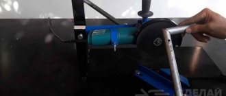
The process of processing sheet metal workpieces performed on a crimping machine, the details of which can also be found in the video, is as follows:
- a stop is pre-installed on the workpiece, the position of which can be adjusted using special screws;
- the processed edge of the part is mounted on the lower roller;
- by rotating the handle, the second roller is lowered onto the edge of the workpiece;
- By rotating the handle of the machine, the rollers and the part sandwiched between them are set in motion.
A creasing machine is a special device designed to perform creasing. Benching is a relatively simple process that is performed on sheet metal parts and involves applying continuous ridges and indentations to the parts.
At the same time, for its full implementation, a special device is required - a manual or automatic crimping machine. The modern market offers many similar machines of various modifications. For those who decide to make such a device with their own hands, we provide detailed instructions.
Purpose and design of beading equipment
Before you begin to understand what a crimping machine is, you need to understand why creasing is performed. In the process of carrying out this technological operation, recesses of a semicircular profile are applied to the surface of the sheet metal workpiece. Such recesses, which are called ridges, act as stiffening ribs; their presence on the surface of a thin-walled metal product makes it much stronger. The size of the recesses, for the formation of which the zig machine is used, completely depends on the thickness of the metal used for the workpiece. To select this parameter, which is very important for such a technological operation, special lookup tables are used.
Many modern manufacturers produce crimping machines, the technical capabilities of which allow them to perform a whole range of technological operations. The operations to which sheet metal blanks are subjected during their circular processing include corrugating their surface, cutting and flanging. More powerful and productive, when compared with manual equipment, are electric crimping machines. Due to the presence of a powerful electric drive in their design, such machines make it possible to successfully process workpieces made of thicker sheet metal.
Main parts of the seaming machine
Regardless of whether the crimping machine is equipped with a manual or electric drive, the design and operating principle of such a machine remain virtually unchanged. The main design elements of such machines are two shafts, the axes of which can be located horizontally or at some angle. It is these shafts, rotating relative to each other in the opposite direction, that impart rotation to the working rollers fixed at their end part. The zig machine works, both manual and electric, according to the following scheme:
- the sheet metal blank is placed between two forming rollers of the equipment;
- the machine shafts are brought together, thereby ensuring clamping of the workpiece between the working rollers;
- using a manual or electric drive, the shafts are rotated;
- when the shafts and working rollers rotate, the part sandwiched between them also begins to move; When a workpiece is moved between working rollers with protrusions of the required size and shape, corresponding depressions are formed on the surface of the sheet metal under the influence of plastic deformation.
Types of sheet bending machines and features of their design
Before you start assembling a manual unit with your own hands, you should accurately determine the volume and list of work that the new device will perform in the future. Indeed, depending on the purpose of this unit, the design diagram of the device may also change.
Of all the solutions available today, the simplest sheet bending machine in terms of design is a product that bends sheet metal using a special traverse. Such a device is useful if you are working with material no more than half a meter wide, allowing you to bend the metal at an angle of 90 degrees without additional devices using only the strength of your own hands.
Sometimes, due to the high elasticity of the material, it is quite difficult to achieve an angle of exact 90 degrees. A special spacer (in the figure on the right), which looks like an ordinary strip of metal, helps to correct the situation.
A press brake consisting of a punch and a die is much more difficult to manufacture. In this case, the sheet metal is placed directly on the die, where the desired profile is given to the workpiece thanks to a punch descending from above.
Let's consider the option of assembling a sheet bending machine with your own hands, which will function in conjunction with a hydraulic press. If you already have a press at home, then adding a device for bending metal will not be difficult.
Practice shows that the sheet bending machine, the operation of which is carried out by 3 shafts, was and remains more advanced in operation. Such a unit is sometimes called a pass-through unit. Its main advantage is that the device makes it possible to produce metal blanks with different bending angles. The metal bending machine can be equipped with either an electric or manual drive, allowing craftsmen to implement a wide variety of designs.
A broaching sheet bender can be additionally equipped with a traverse, a clamp and a support, allowing it to be used for manual bending of material. Machines of this kind are equipped with various shafts, which can always be purchased separately, making the device more versatile.
Profiled rollers are used, as a rule, to give the desired angle to elements of roofing structures, be it flanges, ridges, gutters, valleys, etc.
Rollers with a smooth working surface are used in most cases when it is necessary to carry out tin work, for example, to make sections of pipes of larger diameter or to bend workpieces.
Design Features
The classic design has the following features:
- The main structural element can be called a combination of two plates. Many manufacturers create these plates using the waterjet cutting method. The method under consideration has high accuracy.
- In the formed space between the two plates there are two shafts, which are the main elements in contact with the workpiece.
- Of the two installed shafts, the upper one is movable. Its movement occurs due to a special screw-type clamp. Note that a high-quality homemade zigging machine should have a uniform effect on the entire workpiece, since only in this case a high-quality zigging is obtained.
- The main parameter that can be set using the control unit, manual or automatic, is the zigging depth.
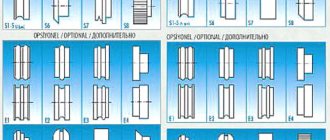
The shape of the ridge can be different, depending on the type of installed rollers. Therefore, when creating a crimping machine with your own hands, you should provide for the possibility of replacing the rollers.
Rollers of creasing machines
Design features of zig machines
One zigovochny device is structurally not too different from another. Their main elements - shafts - are located horizontally, vertically or at an angle. Forming rollers are mounted on the shafts, and the workpiece is secured between them. Due to the opposite movement of the main elements, uniform depressions appear on the metal. With their help, the necessary connection is made.
When choosing a crimping machine, you need to pay attention to the following technical characteristics:
- type of drive;
- diameter and overhang of rollers;
- the number of attached pairs of these parts;
- permissible metal thickness;
- machine size.
The smallest rollers are 50 mm in diameter, their number varies from four to six pairs.
An important indicator is roller overhang. It is better to purchase a machine with a maximum reach - up to 350 mm. This will expand the capabilities of sieving equipment.
The permissible thickness of the metal sheet is from 0.5 mm to 4 mm. The crimping machine will not take up much space (with the exception of CNC machines). Such a device can weigh from 17 to 300 kg.
Before starting work, the workpiece is fixed between the shafts and the handle is turned. On manual machines, due to their low power, it may be necessary to pass the workpiece through the rollers several times.
- https://met-all.org/oborudovanie/prochee/zigovochnaya-mashina-ruchnaya-zigovka-svoimi-rukami-chertezhi.html
- https://stankiexpert.ru/stanki/gibochnye-stanki/zig-mashina-svoimi-rukami.html
- https://metalloy.ru/stanki/zigovochnaya-mashina
- https://stanokgid.ru/metall/ruchnoj-zigovochnyj-stanok-svoimi-rukami.html
- https://prostruky.ru/instrumenty-i-oborudovanie/listogib-svoimi-rukami-instrukciya-i-chertezhi-dlya-samostoyatelnoj-sborki.html
- https://promzn.ru/stanki-i-oborudovanie/izgotovlenie-zigovochnogo-stanka.html
This is interesting: Pellet machine: types and features of machines for the production of pellets
Types of zig machines
Beading machines differ in the type of drive:
- manual;
- hydraulic;
- electromechanical;
- with CNC control.
A manual creasing machine allows you to work with thin sheets, no more than 1.2 mm. The working shafts on which the rollers are placed are brought together using a special handle. The shafts also rotate manually. The crimping machine is secured with a clamp to a stable horizontal surface. Its advantage is mobility and compact size. The disadvantage is that the operator must simultaneously hold the sheets and turn the handle. Which requires some management skills.
Hydraulic and electromechanical equipment bends sheets up to 4 mm thick; it is used in large industries. The rotation of the shafts occurs due to the motor, and the frequency converter allows you to change the operating speed. The equipment is controlled from a remote control or pedal, completely freeing the operator’s hands. The main drive is protected from overload by a special mechanism. Hydraulic machines are made only stationary; the pressure roller is lowered by means of a hydraulic cylinder, easily bending thick metal sheets. The rollers are rotated by an electric motor; its combination with a hydraulic cylinder ensures maximum performance with lower power consumption than electromechanical ones.
Manual seaming machine, classification of rollers and homemade drawings
The creasing machine is used in tin work for joining cylindrical parts, flanging edges and rolling ribs. This is a mandatory stage in the processing of sheet metal products, so the characteristics of crimping must be approached carefully. The executive tool of the zig machine is rolling rollers of various profiles. Each type of roller is designed to perform a specific job. In production, the machine works in conjunction with a folding bender, a guillotine, folding equipment and rollers.
How to make staking equipment with your own hands
Purchasing a serial crimping machine, even a manual type, makes sense if working with sheet metal is part of your professional activity. In all other cases, if such equipment is needed to perform simple work around the house, it is better to make it yourself, especially since it is not so difficult to do
What is important is that such a do-it-yourself machine can be made from very accessible and inexpensive materials
Before you start making your own crimping machine, you need to find drawings of such a device, and you can take serial equipment as a basis. This is not difficult to do, since many home craftsmen post machine drawings and even video instructions on the Internet.
Scheme of a crimping machine
Shaft drawing (the upper shaft is made without space for the handle)
Shaft housing drawing
Zig machine bed: height 25 cm, width determined by the height of the box
Thrust-limiting shield: dimensions 18x20 cm, thickness 0.2-0.3 cm. Side struts are welded
A suitable handle can be selected separately, so as not to have to make it yourself
Drawing of machine working rollers
To assemble your beading machine (even a simple manual type machine), you will need to prepare the following structural elements of the machine:
- device housing with a protective casing;
- bracket;
- cylindrical shank;
- two working shafts;
- retaining bolt;
- screw equipped with a folding handle;
- spring type device;
- gear elements;
- directly the videos themselves.
Homemade manual crimping machine
The device is fastened using a special screw, while the shank of the mechanism fits into the cup of the bracket, around which the machine body must rotate freely. The device body is fixed in a certain position using a locking bolt. A spring mechanism, activated by rotating the handle, is responsible for moving the upper shaft of the machine relative to the lower one.
To rotate the working rollers of the machine, another handle is used, which is connected to the working shafts through a gear drive. To make the work of the operator of such a machine safer, the elements of its gear transmission are covered with a protective casing. On the Internet, you can easily find videos that demonstrate in detail the process of making homemade crimping equipment.
Homemade electrically driven zigging machine
The process of processing sheet metal workpieces performed on a crimping machine, the details of which can also be found in the video, is as follows:
- a stop is pre-installed on the workpiece, the position of which can be adjusted using special screws;
- the processed edge of the part is mounted on the lower roller;
- by rotating the handle, the second roller is lowered onto the edge of the workpiece;
- By rotating the handle of the machine, the rollers and the part sandwiched between them are set in motion.
A creasing machine is a special device designed to perform creasing. Benching is a relatively simple process that is performed on sheet metal parts and involves applying continuous ridges and indentations to the parts.
At the same time, for its full implementation, a special device is required - a manual or automatic crimping machine. The modern market offers many similar machines of various modifications. For those who decide to make such a device with their own hands, we provide detailed instructions.
Classification of serging equipment by drive type
The simplest, both in its design and in its operating principle, is the manual zigovochny machine. All manipulations with such equipment, as its name suggests, are carried out manually. Such manipulations, in particular, include: pressing shafts with working rollers, for which a special handle located in the upper part of the device is used; scrolling the rollers together with the workpiece sandwiched between them: this action is also performed using a special lever-type handle.
To effectively use the simplest manual type crimping machine, certain skills and dexterity are required, since its operator must simultaneously turn the handle and hold the workpiece in the required position, thereby using both hands. Due to the low power of the drive installed on it, a manual creasing machine can be used for processing sheet blanks whose thickness does not exceed 1.5 mm.
Manual crimping machine is suitable for occasional use in the home workshop
A more powerful, productive, but also more expensive in terms of cost is an electrically driven staking machine. Such zigging machines are most correctly classified as electromechanical equipment, since their design also includes a manual mechanical drive, which ensures compression of the sheet workpiece between the working rollers. Due to the electric drive of such equipment, the working rollers rotate and, accordingly, the rotational movement of the workpiece being processed.
The electric drive of the machine is switched on and off using a foot pedal, so that both hands of the operator always remain free to manipulate the workpiece. The presence of an electric drive, which is equipped with such beading machines, as mentioned above, significantly increases their productivity, which makes it possible to successfully use these machines to equip enterprises producing metal products in large batches. In addition, the power of such a machine allows it to be used for processing sheet metal workpieces, the thickness of which reaches 5 mm.
Electromechanical creasing machines, as a rule, can be equipped with additional devices for processing workpieces of complex configurations
Sealing machines can also be equipped with a hydraulic drive, which further increases the power of the equipment. The technical capabilities of such machines make it possible to successfully use them for processing sheet metal of even fairly significant thickness. The hydraulic drive of this type of beading equipment is responsible for pressing the working rollers to the surface of the workpiece, and their rotation and, accordingly, the movement of the workpiece is provided by an electric drive mechanism. Despite all the advantages that hydraulic crimping machines have, they also have disadvantages: large overall dimensions and significant weight, which is why such equipment is mainly used by large manufacturing enterprises.
Design and principle of operation
The zig machine consists of several elements:
- lower, upper shaft;
- handle for rotating shafts (for manual machines);
- screw for adjustment;
- rollers with the help of which parts are processed;
- gears transmitting rotational force between moving shafts;
- housings made of impact-resistant materials;
- cast bed for stable holding of the machine.
Regardless of whether the installation is equipped with an electric drive or not, there are no significant changes in the design or operating process. Zigovka is carried out in several stages:
- The parts are fixed between movable rollers.
- The shafts are aligned to securely hold the workpiece.
- The operator begins to rotate the handle or starts the electric drive.
The workpiece begins to rotate behind the shaft. The depressions are formed under the pressure of the protrusions on the rollers.
Machine structure (Photo: Instagram / stankoprom)
Making at home
If you do not want to buy a factory-made crimping machine, you can make it yourself. This option is suitable for those who work with metal in home workshops and in limited quantities. For industrial enterprises, it is better not to use self-made equipment.
One of the advantages of a homemade machine is its simplicity and low cost of production. All the main parts can be easily found on your farm or purchased on the market. Of course, the number and nature of the parts depends on the type of device you are going to make. There are several options for producing a zig machine at home. We offer one of them.
To create the device you should prepare the following parts:
- Bracket.
- Working shafts (2 pieces).
- Cylinder shank.
- Device body.
- Protective cover.
- Device with a spring.
- Locking pin.
- Gear parts.
- Screw with folding handle.
- Rollers.
The device can be secured using a special screw, but this should be done in such a way that the shank of the mechanism fits into the bracket. The body of the device must be fixed in one position using a locking pin. Using the handle, you can regulate the movement of the apparatus shafts.
The rollers of a homemade zig machine are driven by another handle and by means of a toothed belt drive. When creating your own machine, be sure to ensure that the transmission elements are covered with a special casing.
Such a structural element will certainly make the operator’s work safer. For detailed information, watch the corresponding videos, of which there is no shortage on the Internet.
Video: Homemade manual ZIG machine.
What do you need to know when working with a homemade zig machine?
A zig machine made independently is no different in operating principle from a factory machine, but still has some nuances that must be taken into account. These are such as:
- The part to be processed must be very securely fixed.
- The prepared workpiece must be placed between the rollers and secured with a special stop.
- The process involves adjusting the upper roller, which is operated by a handle.
To avoid injury, be sure to cover all parts of the rotating mechanism with a protective cover. One of the most important advantages of this equipment is that when used, the material used is not exposed to high temperatures.
And also no additional financial costs are required, for example, there is no need to use fuel or large amounts of electricity. And if you use a manual zig machine, then only physical strength is required.
Areas of application for creasing equipment
Equipment designed to perform beading, even though the name of such a technological operation is familiar mainly to metalworking specialists, is actively used in various fields of activity. Sealing machines are practically indispensable for the manufacture of elements of roofing structures, in particular, for the formation of their edges.
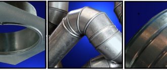
Examples of drainage elements made on a crimping machine
It should be noted that in the construction industry, bending machines have found very wide application. Using such machines, in particular, the following elements of building structures and communication systems are made from sheet metal: parts of drainage and air duct systems, insulation for heating mains, etc. In the construction industry, manual staking equipment is predominantly used, since it is characterized by its small dimensions and insignificant weight, does not require an electrical supply for its operation and can be used almost anywhere.
The creasing machine can also be used to reliably connect cylindrical workpieces made of thin sheet metal together. Rollers for equipping a zig machine of this type, when a cylindrical workpiece passes through them, form locks on it, with the help of which the two parts are connected.
Rolling the lock on the air duct elbow
When making connections using locks, unlike welding, there is no thermal effect on the metal parts, which eliminates the possibility of their warping. In addition, such a machine, which you can also make yourself, does not require any additional consumables for its use.
To expand the functionality of a staking machine, including a manual one, it can be equipped with additional working parts. Machines equipped in this way can be used not only as creasing equipment, but also as bending and profiling equipment. Modern creasing machines for industrial use are often equipped with automated control systems, which increases their productivity and accuracy of technological operations performed with their help.
Special attachments allow you to make folds for connecting thin-walled pipes
This is interesting: Elements of artistic cold forging - photos, videos, sketches
Application area
Most often, crimping machines are used in the construction industry. Using such a device, it is possible to produce a whole range of simply irreplaceable structures: elements of air duct systems, drainpipes, spare parts for heating mains. In this field of activity, manual creasing machines are mainly used. They are relatively cheap and have small dimensions. In addition, you do not need to supply electricity to use them.
Crimping machines are often used to process cylindrical parts. The rollers of such a machine, while passing through the cylinder, make special locks on it, to which other parts are attached. This processing method has less negative impact on the workpiece than the welding process. Another advantage of the zig machine is the lack of need for additional consumables.
In addition, a classic crimping machine can be enhanced with additional equipment that will significantly expand its functionality. Using a modified zig machine, you can perform metal bending and profiling. Zig machines can be manual or equipped with an automated control system.
Description of technology
To create a relief image on a thin metal sheet, modern equipment is used - a crimping machine. It is equipped with special rollers, which leave special grooves (ridges) during the process. They can be either flat or have the required volume.
Several operations are performed using a zigging machine, including:
- cutting;
- corrugation;
- flanging.
Depending on the power, the equipment can process metal sheets of different thicknesses. The least powerful are manual zig machines; they are capable of performing operations on metal with a thickness of 0.3 to 1 mm. Electric ones apply relief on thicker sheets - up to 2 mm.
Three types of machines are used for creasing:
- manual zig machines;
- electrically driven equipment;
- hydraulic mechanisms.
The principle of operation in all three types of equipment is the same, only the power and performance differ. There is one more parameter that is important when choosing machines - the location of the shafts on which working rollers with the desired type of relief are put on. The shafts can be positioned horizontally, vertically or obliquely.
The operation of applying a zig to a metal surface is not difficult in itself, but its execution requires care and adherence to technology, because the further strength of the product depends on the correctness of the processing.
The step-by-step process of applying relief looks like this:
- the workpiece is placed on the working surface with the lower roller, the raised upper shaft with the roller on is lowered from above;
- the part is fixed with special clamping screws;
- for reliable fixation and deeper pressing of the relief, a special stop is used;
- powerful electric and hydraulic machines are used to process durable steel sheets of large thickness;
- when applying relief to sheets of soft metal (aluminum, copper alloys), increase the distance between the ridge grooves and their radius;
- the shafts, rotating in the opposite direction to the rollers, exert pressure on the workpiece, as a result of which relief depressions appear.
If the relief is not clearly pronounced after the first operation, it is repeated several times. Metal beveling is considered completed only if sufficient depth of relief is obtained.
Sealing machine: design, do-it-yourself manufacturing, drawings
A creasing machine is specialized equipment that allows you to perform such a technological operation as creasing. This method of processing, which sheet metal blanks are subjected to, is not particularly difficult in technological terms, but to carry out such processing it is necessary to use special machines. Such equipment, presented on the modern market in a wide variety of serial models, can be equipped with a manual, electric or hydraulic drive. If desired, it is easy to make a simple crimping machine with your own hands.
Operation of a seaming machine: applying a double round seam to a cylindrical workpiece
Classification
There are several types of machines for bending profile parts. They differ in type of design, level of complexity, power and other capabilities. Let's take a closer look at them.
Electrical
A special feature of electric machines is the feeding of the pressure roller using an electric drive.
Similar designs are found in large workshops, since they mainly have a stationary structure designed to work with massive parts.
However, there are also compact options adapted for bending small cross-section profiles.
Such machines are successfully used in small workshops or at home. The degree of accuracy of electric roll forming machines is directly related to their size and type of radius control. Electromechanical structures are adjusted by the operator almost manually, but more complex samples undergo digital control of the magnitude of the impact and display the parameters on the display. The higher the level, the greater the weight of the machine and its cost.
Hydraulic
These machines are used for bending massive profiled elements on an industrial scale.
The size and weight of such equipment require a strong concrete base, which allows use only in production conditions.
One of the common types of products of such machines are elements of sewerage or water supply systems.
Hydraulic machines require connection to the power supply network and are serviced only by trained specialists with appropriate approval. Working with such equipment eliminates the need for physical force and provides high-quality and accurate bending. The operation of hydraulic profile benders is characterized by simplicity, the ability to provide significant productivity, and high speed of obtaining results.
Manual
Manual, or mechanical, profile benders are considered affordable and simple devices. They are compact, relatively lightweight, and can be moved within the workshop without the use of auxiliary mechanisms. Manual designs have limited functionality, since their operation requires the participation of the user’s physical strength. In addition, they have a number of disadvantages:
- work only with thin profile types;
- the duration of the process compared to other types of machine design increases significantly;
- poorly controlled radius of deflection of the part;
- difficulty or impossibility of performing several bends of a given size on one part.
Despite these disadvantages, hand-made designs are common and popular among home craftsmen, as they have the necessary properties for self-production:
- compact dimensions;
- simplicity of design;
- availability of parts and components;
- reliability, maintainability.
People who often use manual profile benders achieve considerable success and produce results of a given accuracy.
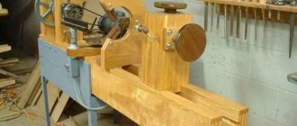
DIY SIG machine
Review of a homemade SIG machine
This SIG machine was developed by the author of the YouTube channel “Nikolai Chernak”. It is based on 2 shafts with a diameter of 35 mm. Installed in bearing housings. The lower shaft is stationary, the housings are tightly welded to the racks, and the upper shaft is movable - it rises up quite high. But you don’t need to lift it like that - it’s convenient until the engagement teeth come out.
When planning, it was taken into account that the axis of rotation is closer to the teeth - but not too much. Because if you place it closer, the body gets stuck. Therefore, it is designed like this: closer to the teeth, at the same time on the edge of the body, so when opening, nothing interferes with anyone.
A gear wheel is used at the rear - a gear pair - it was taken ready-made from the wheel beading mechanism. Previously, during the Soviet Union, kits for passenger cars were sold - trimming, disassembling wheels. I took a gear from it. The gear ratio turned out to be good - easy to rotate.
The steering rod of the car is used in the mechanism for opening the impellers. Convenient – ready-made hinge, just welded, that’s it. Let's weld the screw on the hinge to avoid a break here.
The handle is also made by hand from old car parts; at the end there are balls from steering tips. There is a part feed limiter, i.e. letting the lambs in, you can use it. Parts from shock absorbers were used. Hub of a Minsk motorcycle. To avoid sharpening, motorcycle parts are often used.
The working rollers are made to be removed separately from the hubs. If you unscrew the three screws, the upper part of the impeller is removed. And the hub always remains screwed on. But it has movement along the key. There is a corkscrew. As a result, there is no need for very thick blanks during the production of new rollers. Having narrow workpieces on this ZIG machine, you can grind rollers of different configurations.
Continuation about the SIG machine from 6 minutes.
Zig machine with electric drive
Profile depth 7mm, steel 0.7 – 1.2mm. The serging machine has been ordered and is being tested in operation. It shows what parts it can process and what modifications are required to improve functions.
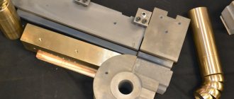
Sealing machine made of gears and rods
The base, that is, the frame should be as rigid as possible. Here is the original version without reinforcement (stiffeners). Discussion
- Hello. Were your fears confirmed or not? I saw about reinforcement in your next video, but how are things going with attaching the rollers? Are they subject to bending?
- Paul Sazhin Hello. Excellent with fastening the rollers. But I will further strengthen the frame since I need to roll a 1.2mm sheet, it moves a little).
- It turned out well, but what car did the shock absorbers come from? Or what is the length and diameter of the rods? Of course, the frame should be strengthened, and it’s better to place the rollers on dowels (or at least on pins), otherwise there is a possibility of scrolling.
- Thank you! From BMW three. Yes, the frame was strengthened, the rod diameter is 22 mm. The throat turned out to be 280 mm. It's too small and narrow for me. It may be enough to make the drive on one upper shaft.
izobreteniya.net
Checking the machine for functionality and fine-tuning
After you have assembled a device for bending sheet metal with your own hands, you need to test it for functionality. To perform test bending, it is better to use a softer metal, which can be a sheet of tin, which bends very well. The sheet is placed on the base of the bending machine and fixed to it using a clamp. When performing test bending, the machine clamp can be temporarily tightened to its base with clamps or threaded rods with overlays can be used for these purposes.
If the position of these structural elements is not entirely correct, it is corrected and only after that they are thoroughly welded to the frame. In order to reliably fix the clamping device of the machine during bending, use bolts protruding above the frame, which must coincide with the holes in the brackets of the clamping mechanism. To install such bolts on the frame, holes are drilled in it into which an M10 thread is cut. The bolts are screwed into such holes from bottom to top, after which their heads are welded to the bottom of the frame.
Installing clamping bolts with springs
To ensure that the bolts installed on the frame easily fit into the holes in the clamping mechanism brackets, they are increased to a diameter of 10 mm. It is better to choose nuts that will screw onto the top of such bolts and thereby fix the clamping mechanism on the frame of the bending equipment in the form of handwheels; this will significantly increase the ease of working with your homemade machine. The clamping mechanism must be pressed out while unscrewing it from the frame. To do this, you can put springs or rubber shock absorbers on the bolts with which it is fixed.
We weld rods to the bolt heads as handles
Having assembled a homemade machine for bending sheet metal using the method described above, you will not wonder how to bend tin or how to bend painted metal: even galvanizing can be processed on this equipment with fairly high efficiency. Meanwhile, such a bending machine also has a number of disadvantages.
- The design of fastening the cheeks and the punch is not well thought out; during the operation of the bending machine, these elements constantly rub against each other and, accordingly, actively wear out. As a result, play occurs in the mechanism, leading to inaccuracies during the bending process. This drawback can be corrected by using bearings in this unit.
- Bending machines of the design described above are not characterized by high productivity and can only be used if it is necessary to perform a small amount of work. To make a more productive manual machine, it is necessary to improve the design of the clamping mechanism.
Homemade bending machine at work
The video is very helpful in making such a machine with your own hands. Typically, many professional tinsmiths who assemble machines for bending sheet metal practically from scrap metal prefer to use homemade equipment in their activities.
Roller-type bending machines, which have a more complex design, can also be made independently. However, no matter what type of machine you are going to make yourself, you should keep in mind that you will operate such equipment manually, so making it too large and powerful does not make sense. If we talk about the features of using roller bending machines, it should be borne in mind that when processing a workpiece on such equipment, its individual sections may be subject to deformation. This is why professional tinsmiths do not really like to work on devices of this type.
The most popular sheet bending design and its improvement
The design of a manual sheet bending machine, shown in drawing No. 1, can be easily improved. From the above drawing it can be seen that the device for bending sheet metal consists of the following elements:
Drawing No. 1: To build our sheet bending machine we will use this diagram
- pillow made of wood;
- support beam made of channel 100–120 mm;
- cheek, for the manufacture of which a sheet 6–8 mm thick is used;
- sheet of material to be processed;
- a pressure beam made of 60–80 mm corners connected by welding;
- an axis for rotating the traverse (made from a metal rod with a diameter of 10 mm);
- the traverse itself is a corner with dimensions of 80–100 mm;
- the handle of the device is made of a rod with a diameter of 10 mm.
The sheet bending traverse (item 7), which according to the original drawing is supposed to be made from a corner, is conventionally shown as a version made from a channel. Such modernization will significantly increase the endurance of the traverse, which, when using a corner, at a certain moment will inevitably bend in the middle and will no longer create a high-quality bend in the sheet in this place. Replacing with a channel will allow you to do not 200 bends without straightening or replacing this element (which is quite a bit for more or less active work), but more than 1300.
Drawing No. 2: Main elements of a sheet bending machine
Drawing No. 2 allows you to understand in more detail the design of a homemade sheet bender:
- a homemade clamp made from a suitable angle (40-60 millimeters) and a screw with a heel and a knob;
- cheek;
- channel acting as a support beam for the machine;
- a clamping beam bracket made from a 110 mm angle;
- the pressing beam of the sheet bender itself;
- axis of rotation of the traverse;
- the traverse itself.
Strengthening the pressure beam
Below we will look at the clamping bar reinforcement scheme. However, if you initially have a fairly massive corner as a clamp, and you do not plan to bend excessively thick sheets on your sheet bending machine, then it is quite possible to do without reinforcing the clamping bar in the described way.
Whether it is worth getting involved with increasing the clamping pressure depends on the operating conditions of the machine
To extend the service life of the pressure beam and make it comparable to the service life of the traverse, this structural element, which was originally made from an angle according to the drawing, should be supplemented with a base made of a metal strip with dimensions of 16x80 mm. The front edge of this base should be given an angle of 45 degrees in order to align its plane with the plane of the clamping angle itself, and the working edge of this element should be chamfered about 2 millimeters.
In drawing No. 2, the resulting part is shown in section in the additional figure at the top right. These measures will allow the clamp metal to work not in bending (which is extremely undesirable), but in compression, thereby greatly increasing the service life without repair.
You should also take care of milling the lower plane of the pressure beam, which forms the bend. The unevenness of this plane, according to generally accepted rules, should not exceed half the thickness of the workpiece being bent. Otherwise, it will not be possible to bend the workpiece evenly, without a swollen fold line. It should be borne in mind that a beam should be submitted for milling only when it already has all the welds, since their implementation leads to a change in the geometric parameters of the structure.
We increase the reliability of machine mounts
There is another big drawback in the sheet bending machine - the way it is attached to the work table. The clamps provided in this device are a very unreliable fastening option, especially considering the rapid fatigue of welds. Such fasteners can be completely abandoned, which will also avoid the need to use welded joints and jaws. The following actions can solve this problem:
- making a support beam that will protrude beyond the desktop;
- making U-shaped eyes at the ends of the support beam;
- fastening the support beam to the work table using bolts (M10) and shaped nuts with claws.
If the improved sheet bending machine no longer has jaws, how can a crossbeam be attached to it? This issue can be solved quite simply: use butterfly door hinges, which are usually used for hanging heavy metal doors. Such hinges, which ensure fairly high accuracy, can be secured using countersunk screws. This is further illustrated in drawing No. 2 at the bottom right.
You can bend a lot of workpieces on a sheet bending machine with a traverse attached to butterfly hinges, since these hinges are very reliable.
Where to start making a sheet bending machine
To make a machine for bending sheet metal, you will need a drawing of such a device or its detailed photos. In addition, a number of important factors should be taken into account, such as the force that will need to be applied to use the sheet bending machine, its weight and dimensions (on which mobility depends), cost and availability of components. As a result, we obtain the following initial parameters.
- The maximum width of the sheet that will need to be bent is 1 m.
- Maximum thickness of sheet material: galvanized – 0.6 mm, aluminum – 0.7 mm, copper – 1 mm.
- The number of operating cycles that will be carried out without readjustment or repair is 1200.
- The maximum bend angle of a metal profile, obtained without manual finishing, is 120 degrees.
- It is highly undesirable to use workpieces made of special steels (for example, stainless steel).
- In the design of a sheet bending machine, welded joints that do not withstand alternating loads should be avoided.
- You should limit as much as possible the number of sheet bending machine parts that you will need to order externally, using turners or millers.
It is very difficult to find a drawing of a device that would satisfy all these requirements, but the most successful one can be modified.