Inverter welding machines are becoming increasingly popular among welders due to their compact size, low weight and reasonable prices. Like any other equipment, these devices can fail due to improper operation or due to design flaws. In some cases, you can repair inverter welding machines yourself by studying the design of the inverter, but there are breakdowns that can only be repaired in a service center.
Welding inverter device
Depending on the model, welding inverters operate both from a household electrical network (220 V) and from three-phase (380 V). The only thing that needs to be taken into account when connecting the device to a household network is its power consumption. If it exceeds the capabilities of the electrical wiring, then the unit will not operate if the network is drained.
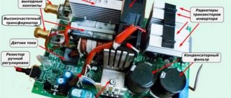
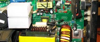
So, the inverter welding machine includes the following main modules.
- Primary rectifier unit. This block, consisting of a diode bridge, is located at the input of the entire electrical circuit of the device. It is this that is supplied with alternating voltage from the mains. To reduce the heating of the rectifier, a heat sink is attached to it. The latter is cooled by a fan (supply fan) installed inside the unit housing. The diode bridge also has overheating protection. It is implemented using a temperature sensor, which breaks the circuit when the diodes reach a temperature of 90°.
- Capacitor filter. It is connected in parallel to the diode bridge to smooth out alternating current ripples and contains 2 capacitors. Each electrolyte has a voltage reserve of at least 400 V, and a capacity of 470 μF for each capacitor.
- Filter for noise suppression. During current conversion processes, electromagnetic interference occurs in the inverter, which can disrupt the operation of other devices connected to this electrical network. To remove interference, a filter is installed in front of the rectifier.
- Inverter. Responsible for converting AC voltage to DC. Converters operating in inverters can be of two types: push-pull half-bridge and full bridge. Below is a diagram of a half-bridge converter with 2 transistor switches, based on devices of the MOSFET or IGBT series, which can most often be seen on inverter devices of the middle price category.
The circuit of a full bridge converter is more complex and already includes 4 transistors. These types of converters are installed on the most powerful welding machines and, accordingly, on the most expensive ones.Just like diodes, transistors are installed on radiators for better heat removal from them. To protect the transistor unit from voltage surges, an RC filter is installed in front of it.
- High frequency transformer. It is installed after the inverter and reduces the high-frequency voltage to 60-70 V. Thanks to the inclusion of a ferrite magnetic core in the design of this module, it is possible to reduce the weight and dimensions of the transformer, as well as reduce power losses and increase the efficiency of the equipment as a whole. For example, the weight of a transformer that has an iron magnetic core and is capable of providing a current of 160 A will be about 18 kg. But a transformer with a ferrite magnetic core with the same current characteristics will have a mass of about 0.3 kg.
- Secondary output rectifier. It consists of a bridge that contains special diodes that respond to high-frequency current at high speed (opening, closing and recovery takes about 50 nanoseconds), which conventional diodes are not capable of. The bridge is equipped with radiators that prevent it from overheating. The rectifier also has protection against voltage surges, implemented in the form of an RC filter. At the output of the module there are two copper terminals, which ensure reliable connection of the power cable and ground cable to them.
- Control board. All operations of the inverter are controlled by a microprocessor, which receives information and controls the operation of the device using various sensors located in almost all components of the unit. Thanks to microprocessor control, ideal current parameters are selected for welding various types of metals. Electronic control also allows you to save energy by supplying precisely calculated and dosed loads.
- Soft start relay. To prevent the rectifier diodes from burning out from the high current of charged capacitors during startup of the inverter, a soft start relay is used.
How to choose a welding machine for your home and garden
Before choosing a welding machine for your home or garden, you should familiarize yourself with the types of power sources for welding and find out what work each type is intended for. The welding transformer should be considered the ancestor of all welding machines. The primary winding was calculated based on the network voltage and the required number of phases. The secondary winding was designed for an output voltage of about 48 Volts. This voltage was considered safe and allowed you to touch the electrode with your hands. With transformers of this type it was possible to obtain welding currents of up to 500 amperes.
You can regulate the current strength in various ways, but all of them are not smooth. The main advantages of welding transformers can be considered extreme simplicity and low cost. The disadvantages include:
characteristic hum during operation;
spattering of metal during the welding process.
And one more, rarely mentioned, but quite significant drawback is the need for a highly qualified welder. Inexperienced welders cannot obtain a high-quality weld on a welding transformer.
Welding rectifier (DC machine)
The advent of power silicon diodes made it possible to add a rectifier to the welding transformer, thereby significantly expanding its functionality. The arc became more stable, even without an additional choke. It became possible to weld metals not only with alternating current, but also with direct current. However, weight and size indicators have not improved, which relegated these devices to the background.
Inverter
Inverter welding machines have made a real revolution. Their appearance coincided with a rise in copper prices on world markets. And the inverter itself uses much less copper than other types of devices. This approach made it possible to make devices accessible to every home and country craftsman, and this is not its least advantage.
Even a beginner can work with such a device. And yet, the main advantage is considered to be minimal weight with the most modest dimensions. If you need a welding machine for your dacha, then it will suit you. By loading it into the trunk of your car, you can use it both in the garage and at the dacha. The disadvantages of the device - a complex implementation scheme, significant cost and expensive repairs - are compensated by a lot of advantages:
a wide range of welded metals;
no metal spattering;
many additional functions that make working with this device comfortable and easy.
Having become acquainted with all the advantages of inverter-type devices, you will no longer think about the question of what choice to make among devices for welding work for household use.
Semi-automatic
Let's continue our excursion into the world of unlimited possibilities of home welding. The presence of inexpensive inverters on the market has led to the expansion of the use of semi-automatic welding machines, in which the inverter acts as a power source. During the welding process, welding wire is used, for which the device has a mechanism for feeding it. Another feature is the use of shielding gases to protect the molten metal and welding zone from oxidation.
How does an inverter work?
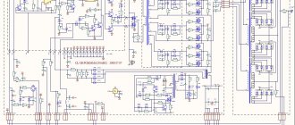
Below is a diagram that clearly shows the principle of operation of a welding inverter.
So, the operating principle of this welding machine module is as follows. The primary rectifier of the inverter receives voltage from the household electrical network or from generators, gasoline or diesel. The incoming current is alternating, but when passing through the diode block it becomes constant. The rectified current is supplied to the inverter, where it is converted back into alternating current, but with changed frequency characteristics, that is, it becomes high-frequency. Next, the high-frequency voltage is lowered by a transformer to 60-70 V with a simultaneous increase in current. At the next stage, the current again enters the rectifier, where it is converted into direct current, after which it is supplied to the output terminals of the unit. All current conversions are controlled by a microprocessor control unit.
Advantages of an inverter device
- The efficiency of the devices reaches 95%. Energy losses are minimal.
- The devices are characterized by increased electrical safety.
- They can be connected to a regular household network without consequences.
- The devices have a very wide range of current regulation. Thanks to this, it is possible to use different types of electrodes and select the required welding mode for metals.
- All operation of the devices is regulated by control circuits and microprocessors. This ensures easy ignition and stable arc retention.
- The voltage and current in inverter devices are adjusted smoothly.
- The devices are equipped with protection against surges in mains voltage.
- Welding can be carried out in any spatial position.
Causes of inverter failures
Modern inverters, especially those made on the basis of an IGBT module, are quite demanding in terms of operating rules. This is explained by the fact that when the unit operates, its internal modules generate a lot of heat. Although radiators and a fan are used to remove heat from power components and electronic boards, these measures are sometimes not enough, especially in inexpensive units. Therefore, you need to strictly follow the rules that are indicated in the instructions for the device, which imply periodically turning off the unit to cool down.
This rule is usually called “On Duration” (DS), which is measured as a percentage. Without observing the PV, the main components of the device overheat and fail. If this happens to a new unit, then this breakdown is not subject to warranty repair.
Also, if an inverter welding machine operates in dusty rooms, dust settles on its radiators and interferes with normal heat transfer, which inevitably leads to overheating and breakdown of electrical components. If the presence of dust in the air cannot be eliminated, it is necessary to open the inverter housing more often and clean all components of the device from accumulated contaminants.
But most often inverters fail when they operate at low temperatures. Breakdowns occur due to the appearance of condensation on the heated control board, resulting in a short circuit between the parts of this electronic module.
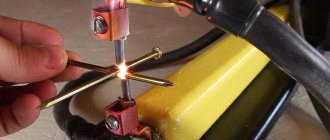
Spot welding diagram
Spot welding is, in short, a process where parts are joined not with a continuous seam, but at several points. This type of welding is used for delicate joining of thin parts; used in mechanical engineering, aviation and other types of precision industries.
In general, the spot welding scheme is as follows. This is a thermoelectric process in which current is passed through the parts to be joined and heats them at the required points. In this case, the strength of the connection depends on the strength of the current and the time of exposure, the compression force of the parts, and their structure. The advantages of spot welding are obvious:
- Lightweight, strong and durable connection.
- Ability to work with delicate materials.
- Low safety voltage.
- High speed.
The spot welding scheme involves applying a controlled current through copper electrodes, the diameter of which determines the energy density. Under the influence of current, a welded core of molten metal is formed - with a diameter of 4 to 12 mm. In this case, different welding modes are distinguished: soft and hard.
Soft involves smooth heating of workpieces with a low current intensity for a relatively long time. Accordingly, less energy is consumed, and such welding requires machines of lower power and cheaper ones. The soft method is used when welding parts that need to be hardened.
The hard method is characterized by higher current values, significant pressure and longer duration of the welding process. Welding machines are selected based on the task, what type of connection needs to be made, and they differ in the types of built-in transformers. In addition to compact devices, there are also multifunctional welding machines.
Repair features
A distinctive feature of inverters is the presence of an electronic control board, so only a qualified specialist can diagnose and repair faults in this unit . In addition, diode bridges, transistor units, transformers and other parts of the electrical circuit of the device may fail. To carry out diagnostics yourself, you need to have certain knowledge and skills in working with measuring instruments such as an oscilloscope and a multimeter.
From the above, it becomes clear that, without the necessary skills and knowledge, it is not recommended to start repairing the device, especially electronics. Otherwise, it can be completely damaged, and repairing the welding inverter will cost half the cost of a new unit.
Frequent malfunctions
The main manifestations of problems with electric arc welding machines are:
- the device does not turn on when connected to the mains and started;
- sticking of the electrode with a simultaneous hum in the area of the converter;
- spontaneous shutdown of the welding machine in case of overheating.
Repairs always begin with an inspection of the welding machine and checking the supply voltage. Repairing transformer welding machines is not difficult, and they are not picky about maintenance. With inverter devices, it is more difficult to determine a breakdown, and repairs at home are often impossible.
However, if handled properly, inverters last a long time and do not break down. It is necessary to protect from dust, high humidity, frost, and store in a dry place. There are the most typical malfunctions of welding machines that you can fix yourself.
Main malfunctions of the unit and their diagnostics
As already mentioned, inverters fail due to the impact of external factors on the “vital” units of the device. Also, malfunctions of the welding inverter can occur due to improper operation of the equipment or errors in its settings. The most common malfunctions or interruptions in the operation of inverters are:
The device does not turn on
Very often this breakdown is caused by a faulty network cable of the device. Therefore, you first need to remove the casing from the unit and ring each cable wire with a tester. But if everything is in order with the cable, then more serious diagnostics of the inverter will be required. Perhaps the problem lies in the standby power supply of the device. The method of repairing the “duty room” using the example of a Resanta brand inverter is shown in this video.
Welding arc instability or metal spattering
This malfunction may be caused by incorrect current setting for a certain electrode diameter.
Advice! If there are no recommended current values on the packaging for the electrodes, then it can be calculated using the following formula: for each millimeter of equipment there should be a welding current in the range of 20-40 A.
Welding speed should also be taken into account. The smaller it is, the lower the current value must be set on the control panel of the unit. In addition, to ensure that the current strength corresponds to the diameter of the additive, you can use the table below.
Welding current is not adjustable
If the welding current is not regulated, the cause may be a breakdown of the regulator or a violation of the contacts of the wires connected to it. It is necessary to remove the unit casing and check the reliability of the conductor connections, and, if necessary, test the regulator with a multimeter. If everything is in order with it, then this breakdown can be caused by a short circuit in the inductor or a malfunction of the secondary transformer, which will need to be checked with a multimeter. If a malfunction is detected in these modules, they must be replaced or rewound by a specialist.
High power consumption
Excessive power consumption, even if the device is without load, most often causes an interturn short circuit in one of the transformers. In this case, you will not be able to repair them yourself. You need to take the transformer to a mechanic to rewind it.
The electrode sticks to the metal
This happens if the network voltage drops. To get rid of the electrode sticking to the parts being welded, you will need to correctly select and configure the welding mode (according to the instructions for the device). Also, the voltage in the network may sags if the device is connected to an extension cord with a small wire cross-section (less than 2.5 mm2).
Often, a drop in voltage causing electrode sticking occurs when using a power extension cord that is too long. In this case, the problem is solved by connecting the inverter to the generator.
Overheat light on
If the indicator is on, this indicates overheating of the main modules of the unit. The device may also turn off spontaneously, which indicates that the thermal protection has tripped. To prevent these interruptions in the operation of the unit from occurring in the future, it is again necessary to adhere to the correct duty cycle (ST). For example, if duty cycle = 70%, then the device should operate in the following mode: after 7 minutes of operation, the unit will be given 3 minutes to cool down.
In fact, there can be quite a lot of different breakdowns and the reasons that cause them, and it’s difficult to list them all. Therefore, it is better to immediately understand what algorithm is used to diagnose a welding inverter in search of faults. You can learn how to diagnose the device by watching the following training video.
Spontaneous shutdown
In some cases, repairs can be carried out independently if the device begins to turn off spontaneously. Most models of welding machines are equipped with a protective circuit (automatic) that is triggered in a critical situation, accompanied by a deviation from normal operation. One of the options for such protection involves blocking the operation of the device when the ventilation module is turned off.
After spontaneous shutdown of the welding machine, first of all, you should check the state of the protection and try to return this element to working condition.
If the protective unit is triggered again, it is necessary to proceed to troubleshooting using one of the methods described above related to short circuits or malfunctions of individual parts.
In this situation, first of all, you should make sure that the cooling unit of the unit is working normally and that overheating of the internal spaces is excluded.
It also happens that the cooling unit does not cope with its functions due to the fact that the welding machine was under a load for a long time that exceeded the permissible norm. The only correct solution in this case is to let it “rest” for about 30-40 minutes, and then try to turn it on again.
In the absence of internal protection, a circuit breaker can be installed in the electrical panel. To maintain normal functioning of the welding unit, its settings must correspond to the selected modes.
Thus, some models of such devices (welding inverter, in particular), in accordance with the instructions, must work according to a schedule that requires a break of 3-4 minutes after 7-8 minutes of continuous welding.
general description
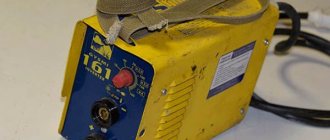
The unpretentious welding machine GY GYSMI (popularly known as “gusmi”) with microprocessors at its core can be used for both manual arc welding and MMA welding.
To simplify your welding work, the GYSMI 161 welding device also has the following functions:
- hot start (Hotstart);
- “anti-sticking” (anti-sticking);
- Arc force;
- equipped with overheating protection;
- air cooling system.
Despite the fact that at a voltage of 170 - 260 V GYSMI operates without any problems, you should not put a large load on the inverter; we advise you to monitor this yourself.
For example: for 10 minutes of welding work, operate the inverter for 5 minutes, and allow the machine to cool for the remaining 5 minutes. The contents in the box are standard and include:
- inverter;
- a travel bag made of thick plastic;
- network cable with European standard plug;
- for transportation on the shoulder-strap;
- welding cable with clamp and holder (2 pcs);
- instructions.
This is interesting: Drills (engravers) for wood carving: varieties, features, selection rules