Moreover, the use of the latter is now recognized as more reasonable. Installed on the radiator.
The result obtained is associated with the output of a direct welding current, the strength of which is very high and the voltage is low. The bridge modifies the current from alternating to direct.
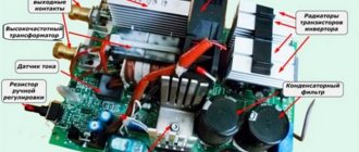
A voltage-reducing transformer installed behind the inverter unit allows you to obtain a current of sufficient strength at the output of the device so that you can effectively perform welding work with its help. Schemes of homemade and factory welding inverters.
The resistor resistance is 47 ohms. The new version has three pulse transformers, while the old one only has two.
Possible malfunctions and ways to eliminate them Even reliable electronic components can sometimes fail; breakdowns occur when welding inverters are used incorrectly. At the same time, the welding current increases, which exceeds A. Here is the diagram.
To ensure air circulation, an air gap is left between the windings.
The sensor is triggered when the critical heating temperature of any element is reached.
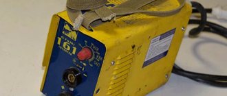
REPAIR OF WELDING INVERTER INTERSKOL ISA 250/10, 6
Typical circuit and principle of operation of the inverter
This is the main role of transformer T3. Read more. To power the microcircuits and elements located on the control board, a 15-volt integrated stabilizer - LMA - is used. According to the principle of operation, it is very similar to switching power supplies, for example, AT and ATX computer power supplies. Checking functionality After assembly and debugging work, the functionality of the welding machine is checked. The switch module is represented by four transistors in each of the four groups.
The additional arrangement of 0.15 µF capacitors allows excess power to be dumped back into the circuit.
At the same time, the principle of operation of the latter remains unchanged.
The transformer steps down the current to a voltage level equal to V.
This is where the rectifier comes into play, ensuring that the incoming current has constant parameters.
The resistor resistance is 47 ohms. Open circuit voltage 62 V. TWO in ONE. WELDING + INDUCTION FURNACE. Short review. Welding machine - heater 2 in 1
Welding inverter mma 200 circuit
Good day to all. There is a Svarog Real 200 Arc machine, purchased as a donor for PA welding. I visually tinkered with the diagram. There is a shunt on the minus side. A voltage of 66 mV is removed from it in short-circuit mode with a 4 mm electrode. But there is also a CT on the primary of the power transformer. It gnawed the track that goes to the OS op-amp. I connected the oscilloscope. I applied the load to the output of the welder, the pulse width of the SG3225AP output does not change. Restored the path. Now, when you connect a ballast resistor and turn the current to a minimum, the pulse width goes to a minimum. Conclusion, current feedback goes through the shunt. Have questions. Why then would a TT be used as a primary power trance? To limit the MAX current? What do the guts of this welder look like? Does anyone have a wiring diagram for similar giblets of this welding machine? How to upload a photo?
andrejapanov wrote: Why then is TT on the primary power trance?
The main element of the simplest welding machine is a transformer operating at a frequency of 50 Hz and having a power of several kW.
Therefore, its weight is tens of kilograms, which is not entirely convenient. welding inverters have become widespread . Their main advantages: small dimensions, smooth adjustment of welding current, overload protection. The weight of a welding inverter with a current of up to 250 Amps is only a few kilograms.
The operating principle of the welding inverter is clear from the block diagram below:
An alternating mains voltage of 220 V is supplied to a transformer-free rectifier and filter (1), which generates a constant voltage of 310 V. This voltage powers a powerful output stage (2). The input of this powerful output stage is supplied with pulses with a frequency of 40-70 kHz from the generator (3). The amplified pulses are supplied to the pulse transformer (4) and then to a powerful rectifier (5) to which the welding terminals are connected. The control and overload protection unit (6) regulates the welding current and protects it.
Since the inverter operates at frequencies of 40-70 kHz and higher, and not at a frequency of 50 Hz, like a conventional welder, the dimensions and weight of its pulse transformer are tens of times smaller than a conventional 50 Hz welding transformer. And the presence of an electronic control circuit allows you to smoothly regulate the welding current and provide effective protection against overloads.
Let's look at a specific example.
The inverter stopped cooking. The fan works, the indicator lights up, but the arc does not appear.
This type of inverter is quite common. This model is called "Gerrard MMA 200 "
We managed to find a diagram of the “MMA 250” inverter, which turned out to be very similar and significantly helped in the repair. Its main difference from the required MMA 200 :
- The output stage has 3 field-effect transistors connected in parallel, while the MMA 200 has 2 each.
- There are 3 output pulse transformers, while the MMA 200 has only 2.
The rest of the scheme is identical.
Briefly about the scheme itself.
At the beginning of the article, a description of the block diagram of a welding inverter is given. From this description it is clear that the welding inverter is a powerful pulsed power supply with an open circuit voltage of about 55 V, which is necessary for the occurrence of a welding arc, as well as an adjustable welding current, in this case, up to 200 A. The pulse generator is made on the U2 microcircuit type SG3525AN, which has two outputs for controlling subsequent amplifiers. The generator U2 itself is controlled through an operational amplifier U1 type CA 3140. This circuit regulates the duty cycle of the generator pulses and thus the output current, which is set by a current control resistor located on the front panel.
Types of inverter welding current sources
Housing with cooling fan.
Schematic diagram of inverter-type devices In order to understand the essence of the operation of a modern welding unit, it is necessary to know what blocks the schematic diagram of a welding inverter consists of, which provides energy for the short circuit arc during the welding process.
It consists of 2-4 capacitors and a choke.
These situations can occur due to insufficient cooling of power elements at high ambient temperatures, as well as when working in a dusty or too humid atmosphere. Moreover, the use of the latter is now recognized as more reasonable. How does a welding inverter work? Generating a high current that creates an electric arc to melt the edges of the parts being joined and the filler material is what any welding machine is designed for.
This element supplies electric current to the power part of the welding unit. Let's look at the described scheme in a little more detail.
In humid conditions, leaks may occur, which may also cause malfunction. The electrical circuit of the inverter includes the following required components: Power supply unit.
An important step is solving the problem associated with choosing the necessary technology that optimizes the operation of the power unit. The device includes a power transformer. To improve thermal contact, you need to use silicone thermal paste.
If it simply boils, it means that there are shortcomings in the scheme and it is better not to continue the work. Reducing high frequency voltage; 4. Exceptional stability of the voltage supplied to the welding arc is ensured by the automatic elements of the inverter electrical circuit. Therefore, in case of repairs, diodes in the output rectifier should be replaced with high-speed diodes. Repair of welding inverter Resanta 190A. Repair welding inverter 190A Resanta does not turn on
CHINESE INVERTERS
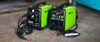
Nowadays there are almost no people left who, when going to the store for a welding machine, would opt for a traditional welder with a large transformer. Inverter-type welding machines (with a built-in converter) have such undeniable advantages over conventional ones that their only drawback is their high price.However, the situation has changed with the massive arrival of inexpensive, even cheap, Chinese inverters into our markets. Of course, an experienced electronics engineer can assemble a welding device with his own hands, but in our regional shopping center the price of industrial Chinese inverters is only 170 - 300 euros. So is the game worth the candle? Of course, the reliability of the Chinese inverter is not great, but with a one-year warranty it’s worth it. Here are the parameters of some popular models of Chinese welding inverters presented in online stores. Typical circuit of a Chinese inverter, using the TIG200 model as an example.
NBC Welding Inverter
Inverter model NBC-350 NBC-500 NBC-630 Input voltage 380+/-10% 380+/-10% 380+/-10% Power consumption, kW 14 25 37 Current consumption 25 46 66 Welding voltage 14-40 17- 50 17-50 Welding current 60-350 60-500 60-630 Electrode diameter 0.8-1.6 1.0-1.6 1.0-2.0 Efficiency 89% 89% 89%
TIG welding inverter
Inverter model TIG-160 TIG-200 TIG-250 TIG-315 TIG-400 Current consumption 20A 28A 9.6A 13.6A 20A No-load voltage. 56V 56V 54V 68V 60V Welding current 15-160A 15-200A 15-250A 15-315A 15-400A Load voltage 16.4V 18V 20V 22.6V 26V Efficiency 0.8 0.8 0.8 0.8 0.8
Welding inverter WS
Inverter model WS-160 WS-200 WS-250 WS-315 WS-400 No-flow voltage. 56V 56V 54V 68V 60V Welding current 15-160A 15-200A 15-250A 15-315A 15-400A Efficiency 0.8 0.8 0.8 0.8 0.8
Welding inverter CUT
Inverter model CUT-40 CUT-60 CUT-80 CUT-100 Input voltage 220+/-10% 380+/-10% 380+/-10% 380+/-10% Frequency (Hz) 50/60 50/60 50/60 50/60 Current consumption 22 11.9 17 22.8 No-load voltage. 230 240 240 240 Welding current 15-40 15-60 15-80 20-100 Load voltage 96 104 112 120
MMA welding inverter
Inverter model MMA-160 MMA-200 Welding current 15-160 15-200 Current consumption 33 43 No-load voltage. 56 56 Electrode diameter 1.6-2.5 1.6-3.2 Load voltage 26.4 28 Efficiency 80% 80%
Main advantages of inverters:
The welding inverter is great for welding low carbon steel, alloy steel; Advanced high frequency switching inverter technology, high reliability, small size, light weight, energy saving; Wire arc retarder, high accuracy; Anti-stick electrode; Special control technology to improve the shape, reduce spatter, welding distortion, good welding shape, displacement level; Passive power factor correction is used; Current, voltage - smoothly adjustable over a wide range of values; The welding work cycle can be long and continuous; Affordable price in online stores.
Forum on Chinese inverters
Forum for discussing the material CHINESE INVERTERS
WIRELESS POWER POWER POSSIBILITIES
About the use of wireless power technology for various devices.
What are OLED, MiniLED and MicroLED TVs - a brief overview and comparison of technologies.
Provides basic information about planar fuses, including their technical characteristics and applications.
Welding inverter circuits
Possible malfunctions and ways to eliminate them Even reliable electronic components can sometimes fail; breakdowns occur when welding inverters are used incorrectly.
All welding machines are divided into several main groups: To carry out electric arc welding when using electrodes coated with a special composition, MMA type equipment is used. Below we present a block diagram of the functioning of a standard inverter, which clearly demonstrates the principle of its application. Possible malfunctions and ways to eliminate them Even reliable electronic components can sometimes fail; breakdowns occur when welding inverters are used incorrectly.
Soldering the board.
Conclusions The inverter is a complex electronic device, but easy to use; it is connected to an electrical circuit with voltage V and welding can be carried out without fear. During testing, turns should be added until the arc begins to stretch noticeably strongly, preventing separation.
Swaris device diagrams
The capacitors installed in the filter, after charging is activated, are capable of delivering a high current that burns, so the inverter is provided with a smooth start. Despite the use of a similar circuit when creating almost all inverters, they differ significantly from each other. The electrical circuit assumes the operation of the unit based on high-frequency pulse converters. Conventional rectifier diodes would not be able to cope with such a task - they simply would not have time to open and close, would heat up and fail.
Possible malfunctions and ways to eliminate them Even reliable electronic components can sometimes fail; breakdowns occur when welding inverters are used incorrectly. The switch module is represented by four transistors in each of the four groups. Then the current is equalized in the presence of a capacitor and flows to the transistor unit.
Circuit diagram in detail: components
Thus, at the first stage, we receive a direct current at the output from the rectifier, having a value of more than V. Previously, welding inverters used transformers that were very powerful, operated by the winding of the transformer and, because of this, had dimensions and weight that made welding machines bulky and inconvenient to use. The inverter device once again converts the electric current, now into alternating current, while increasing its frequency.
Huge currents flow through them. Part 1. When constructing a secondary winding, the turns are wound in several layers. If the wire voltage is less than V, then the device is faulty. Chinese inverter circuit
I present the smallest, lightest and fairly easy to use welding inverter. It allows you to carry out welding work with electrodes with a diameter of up to 3 mm.
Inverter characteristics
- Dimensions (LxWxH) - 180x105x80;
- Weight - 1100 grams;
- Current - 80A, can be squeezed up to 100A;
- Idle current - 170-200mA;
- Open circuit voltage is 60 volts.
The inverter is assembled in a computer power supply housing.
Due to the lack of space in this case, it was not possible to provide good airflow to the radiators of the power components, so it is not intended for long-term operation, but it can be used to burn several electrodes in a row.
Making an inverter from scratch is quite expensive, good original parts are expensive, you need experience working with switching power supplies and in power electronics in general, it is better and more profitable to buy a factory inverter, and if you decide to assemble it, then make a full-size inverter and don’t skimp on cooling.
Inverter circuit
This welding inverter is a single-cycle forward converter built on a UC3844 PWM controller. The output of the microcircuit controls the IGBT transistor through the driver. The circuit is equipped with soft start and overheating protection. Current feedback is implemented through a current transformer.
The inverter is assembled on three boards:
- all power components, transformer, inductor, rectifiers, power transistor and input circuit are located on the motherboard;
- control circuit;
- standby power supply.
Control circuit
More than half of the components that are on the diagram are on this compact printed circuit board
In the author’s version, the entire circuit is assembled on one board, but in my case, to make the device as compact as possible, the controls were transferred to a separate board. It turned out to be very compact, it is extremely difficult to make less if you use output components rather than SMD. The installation is very tight, there is only one jumper on the board.
After assembly, the board was tested. A voltage of about 30 volts is supplied to the input of the stabilizer or diode. We close the base and emitter of transistor VT1 with each other, simulating a closed thermal switch, otherwise the overheating protection will work and the relay will close the current regulator and, as a result, the microcircuit will stop generating a sequence of pulses. We connect an oscilloscope probe to the driver output and observe a beautiful square wave with a frequency of about 30 kHz and a fill of about 44 percent. We check the protection by removing the previously installed jumper. The relay should operate, the red LED should light up and the operation of the PWM chip should be blocked. The control board is ready, this part does not need additional adjustment if everything is assembled correctly, the components are in good condition and there are no snot on the board.
The original circuit operates at a frequency of 30 kHz, initially I wanted to raise it, and also by changing the ratio of the number of winding turns to remove more power from the core, but the final calculations showed that even at 30 kilohertz, a power of about 2-2 can be easily taken from the core, 2 kW, and this is about 80-90 Amperes of current, if you take into account the voltage drop during welding, to about 24 volts.
Taking this into account, the device copes with 3mm electrodes without any problems, but in my insurance unit the maximum current is limited to 80 Amps.
Power transformer
Since the welding machine was planned for a small output current of around 80 amperes, the transformer will seem small, but it is enough, although it works almost to the limit of its capabilities.
The circuit is single-ended and a non-magnetic gap of 0.1-0.2 mm is needed between the halves of the core; such a gap can be created without problems if you use a core of two halves, for example W-shaped. But the problem was that I did not have such a core with the required overall power; the only more or less good cores were ring-type with dimensions 47x26.5x15.5mm. Such a core will work perfectly in a push-pull circuit; in a single-stroke circuit, a gap is needed.
First we make markings, then we saw the core, not completely, half a millimeter is enough.
Next, we install the core on wooden blocks approximately as shown, place a metal rod in the center at the cut site and carefully but firmly hit it with a hammer. As a result, we get two even halves. Next, take a receipt from an ATM, cut two strips and glue them to one of the halves using superglue, you don’t need a lot of glue.
We tighten the halves of the core with, for example, Kapton tape. In general, this core has insulation in the form of paint, but additional insulation will not be superfluous.
After we wind the primary winding, in my case a 1.2mm wire was used for winding, the calculation was made according to the program, naturally in the case of other cores we will get different winding data, so I see no point in indicating the number of turns. In this diagram, it is very important to observe the beginning of the winding; in the diagram they are indicated by dots, therefore, after winding each of the windings, it is advisable to mark the beginning of the winding.
The turns are evenly stretched throughout the ring; after winding, we put insulation and wind the fixing winding.
The number of turns is the same as in the case of the primary winding, but the wire is naturally thinner, I used 0.3mm wire.
You need to wind it so that the turns of the fixing winding are between the turns of the primary winding.
After winding the fixing winding, we again install insulation and wind the secondary winding of 80 parallel wires with a 0.22 mm wire. The harness is additionally insulated with Kapton tape.
The current transformer is wound on a small ring ferrite magnetic core, core permeability 2400.
First, the core was insulated with Kapton tape, then the secondary winding was wound. The number of turns is about 80; wire with a diameter of 0.24 mm was used for winding. The winding is evenly stretched across the entire ring. The secondary winding is one turn with a double wire of 1.2 mm.
For the output choke, a torus measuring 38.8x21x11.4 mm made of powdered iron was taken as a core. The ring has a green-blue color and is specifically designed to work as an output choke.
For winding, a bundle of 80 cores of wires insulated from each other with a diameter of 0.22 mm each was used, that is, exactly the same as in the case of the secondary winding of the transformer.
The inductance of the inductor turned out to be about 35 microhenry and this is not enough; it is desirable to make the inductance in the region from 80 to 120 μH.
The inductor winding terminals were cleared of varnish and tinned.
A few words about components
Input electrolyte 450 volts with low internal resistance, from a good manufacturer, capacity 470 μF.
The relay in the soft start circuit is a full-size 30-amp one, like in large inverters, although the board was originally designed to install a more compact relay.
The power IGBT transistor and diodes in the high-voltage circuit of the converter are as per the diagram, no deviations.
The output rectifier uses STTH6003 high-speed diode assemblies. In one such assembly there are 2 diodes with a current of 30 amperes, the cathode is common, the anodes are also connected in parallel, as a result we get an analogue of a 60-amp diode, the reverse voltage of the assembly is 300 volts.
The assemblies are installed on a common radiator; the substrates are not isolated, because The cathodes are common, the output plus is removed from the radiator.
The input rectifier is in the form of a ready-made KBJ2510 diode bridge, with a current of 25 amperes and a reverse voltage of 1000 volts.
The resistor in the soft start circuit is 5-10 watts, resistance 10-30 ohms.
Standby power supply
This is a ready-made universal power source, which was purchased on Ali and is designed to work in induction cookers as a standby, with a power of about 7 watts.
It produces three voltages: 5 volts, 12 volts and 18 volts. The output voltages are set by an 18-volt zener diode. I replaced this zener diode with a 24-volt one, threw out the 5-volt circuit, replaced some output capacitors with higher-voltage ones, and as a result, the control room began to produce two voltages: 15 volts and 24 volts.
The first voltage is needed to power the fan, I have it at 12 volts, the second voltage powers the control and relay. This duty station has a soft start, protection against short circuits, and is built on just one microcircuit.
The cooling radiators are taken from computer power supplies; taking into account the presence of active cooling and the maximum welding current, they are sufficient.
After assembly, the device worked immediately, without any deviations. The first launch was done through a 100-watt safety lamp; on the oscilloscope, the shape of the pulses on all windings is correct, the open-circuit voltage is about 60 Volts.
We check the operation of the current limiting system. To begin with, we set the current regulator to a minimum, hook an oscilloscope to the gate of the power transistor and make a short circuit at the output, we see that the duration of the control pulses decreases sharply, the current is limited, if this does not happen, we swap the beginning and end of the secondary winding of the current transformer.
The power tracks on the printed circuit board are additionally reinforced with copper tapes.
Output terminals from a powerful 12-220 Volt converter.
For reliability, the transformers, inductor and a pair of vertical boards were additionally glued to the motherboard using epoxy resin.
At the ballast, the inverter produced an honest 80 amperes, the minimum current was around 20 amperes, and we had reliable arc ignition. Thanks to the low minimum current, even thin sheet metal can be welded.
Printed circuit board
Sincerely - AKA KASYAN