Inverter welding machines are becoming increasingly popular among welders due to their compact size, low weight and reasonable prices. Like any other equipment, these devices can fail due to improper operation or due to design flaws. In some cases, you can repair inverter welding machines yourself by studying the design of the inverter, but there are breakdowns that can only be repaired in a service center.
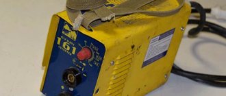
Welding inverter device
Depending on the model, welding inverters operate both from a household electrical network (220 V) and from three-phase (380 V). The only thing that needs to be taken into account when connecting the device to a household network is its power consumption. If it exceeds the capabilities of the electrical wiring, then the unit will not operate if the network is drained.
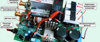
So, the inverter welding machine includes the following main modules.
- Primary rectifier unit. This block, consisting of a diode bridge, is located at the input of the entire electrical circuit of the device. It is this that is supplied with alternating voltage from the mains. To reduce the heating of the rectifier, a heat sink is attached to it. The latter is cooled by a fan (supply fan) installed inside the unit housing. The diode bridge also has overheating protection. It is implemented using a temperature sensor, which breaks the circuit when the diodes reach a temperature of 90°.
- Capacitor filter. It is connected in parallel to the diode bridge to smooth out alternating current ripples and contains 2 capacitors. Each electrolyte has a voltage reserve of at least 400 V, and a capacity of 470 μF for each capacitor.
- Filter for noise suppression. During current conversion processes, electromagnetic interference occurs in the inverter, which can disrupt the operation of other devices connected to this electrical network. To remove interference, a filter is installed in front of the rectifier.
- Inverter. Responsible for converting AC voltage to DC. Converters operating in inverters can be of two types: push-pull half-bridge and full bridge. Below is a diagram of a half-bridge converter with 2 transistor switches, based on devices of the MOSFET or IGBT series, which can most often be seen on inverter devices of the middle price category.
The circuit of a full bridge converter is more complex and already includes 4 transistors. These types of converters are installed on the most powerful welding machines and, accordingly, on the most expensive ones.Just like diodes, transistors are installed on radiators for better heat removal from them. To protect the transistor unit from voltage surges, an RC filter is installed in front of it.
- High frequency transformer. It is installed after the inverter and reduces the high-frequency voltage to 60-70 V. Thanks to the inclusion of a ferrite magnetic core in the design of this module, it is possible to reduce the weight and dimensions of the transformer, as well as reduce power losses and increase the efficiency of the equipment as a whole. For example, the weight of a transformer that has an iron magnetic core and is capable of providing a current of 160 A will be about 18 kg. But a transformer with a ferrite magnetic core with the same current characteristics will have a mass of about 0.3 kg.
- Secondary output rectifier. It consists of a bridge that contains special diodes that respond to high-frequency current at high speed (opening, closing and recovery takes about 50 nanoseconds), which conventional diodes are not capable of. The bridge is equipped with radiators that prevent it from overheating. The rectifier also has protection against voltage surges, implemented in the form of an RC filter. At the output of the module there are two copper terminals, which ensure reliable connection of the power cable and ground cable to them.
- Control board. All operations of the inverter are controlled by a microprocessor, which receives information and controls the operation of the device using various sensors located in almost all components of the unit. Thanks to microprocessor control, ideal current parameters are selected for welding various types of metals. Electronic control also allows you to save energy by supplying precisely calculated and dosed loads.
- Soft start relay. To prevent the rectifier diodes from burning out from the high current of charged capacitors during startup of the inverter, a soft start relay is used.
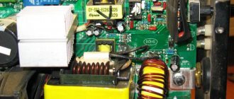
Improved heat dissipation
The first drawback that plagues the vast majority of inexpensive inverter devices is a poor heat removal system from power switches and rectifier diodes. It is better to begin improvements in this direction by increasing the intensity of forced airflow. As a rule, case fans are installed in welding machines, powered by 12 V service circuits. In “compact” models, forced air cooling may be completely absent, which is certainly nonsense for electrical equipment of this class.
It is enough to simply increase the air flow by installing several of these fans in series. The problem is that the “original” cooler will most likely have to be removed. To operate effectively in a sequential assembly, fans must have an identical shape and number of blades, as well as rotation speed. Assembling identical coolers into a “stack” is extremely simple; just tighten them with a pair of long bolts along diametrically opposite corner holes. Also, do not worry about the power of the service power supply; as a rule, it is enough to install 3–4 fans.
If there is not enough space inside the inverter housing to install fans, you can install one high on the outside. Its installation is simpler because it does not require connection to internal circuits; power is removed from the power button terminals. The fan, of course, must be installed opposite the ventilation louvers, some of which can be cut out to reduce aerodynamic drag. The optimal direction of air flow is towards the exhaust from the housing.
The second way to improve heat dissipation is to replace standard aluminum radiators with more efficient ones. A new radiator should be selected with the largest number of fins as thin as possible, that is, with the largest area of contact with air. It is optimal to use computer CPU cooling radiators for these purposes. The process of replacing radiators is quite simple, just follow a few simple rules:
- If the standard radiator is isolated from the flanges of the radio elements with mica or rubber gaskets, they must be preserved when replacing.
- To improve thermal contact, you need to use silicone thermal paste.
- If the radiator needs to be trimmed to fit into the case, the cut fins must be carefully processed with a file to remove all burrs, otherwise dust will accumulate on them abundantly.
- The radiator must be pressed tightly against the microcircuits, so you first need to mark and drill mounting holes on it; you may need to cut a thread in the body of the aluminum base.
Additionally, we note that there is no point in changing the piece heatsinks of separate keys; only the heat sinks of integrated circuits or several high-power transistors installed in a row are replaced.
How does an inverter work?
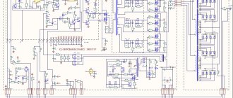
Below is a diagram that clearly shows the principle of operation of a welding inverter.
So, the operating principle of this welding machine module is as follows. The primary rectifier of the inverter receives voltage from the household electrical network or from generators, gasoline or diesel. The incoming current is alternating, but when passing through the diode block it becomes constant. The rectified current is supplied to the inverter, where it is converted back into alternating current, but with changed frequency characteristics, that is, it becomes high-frequency. Next, the high-frequency voltage is lowered by a transformer to 60-70 V with a simultaneous increase in current. At the next stage, the current again enters the rectifier, where it is converted into direct current, after which it is supplied to the output terminals of the unit. All current conversions are controlled by a microprocessor control unit.
Units suitable for modernization
The most important parameter of any welding machine is the current-voltage characteristic (CVC), which ensures stable arc burning at different arc lengths. The correct current-voltage characteristic is created by microprocessor control: the small “brain” of the inverter changes the operating mode of the power switches on the fly and instantly adjusts the parameters of the welding current. Unfortunately, it is impossible to reprogram a budget inverter in any way - the control microcircuits in it are analog, and replacement with digital electronics requires extraordinary knowledge of circuit design.
However, the “skills” of the control circuit are quite enough to level out the “crookedness” of a novice welder who has not yet learned to hold the arc stably. It is much more correct to focus on eliminating some “childhood” diseases, the first of which is severe overheating of electronic components, leading to degradation and destruction of power switches.
The second problem is the use of radioelements of questionable reliability. Eliminating this drawback greatly reduces the likelihood of breakdowns after 2–3 years of operation of the device. Finally, even a novice radio engineer will be quite capable of implementing an indication of the actual welding current to be able to work with special brands of electrodes, as well as carry out a number of other minor improvements.
Causes of inverter failures
Modern inverters, especially those made on the basis of an IGBT module, are quite demanding in terms of operating rules. This is explained by the fact that when the unit operates, its internal modules generate a lot of heat. Although radiators and a fan are used to remove heat from power components and electronic boards, these measures are sometimes not enough, especially in inexpensive units. Therefore, you need to strictly follow the rules that are indicated in the instructions for the device, which imply periodically turning off the unit to cool down.
This rule is usually called “On Duration” (DS), which is measured as a percentage. Without observing the PV, the main components of the device overheat and fail. If this happens to a new unit, then this breakdown is not subject to warranty repair.
Also, if an inverter welding machine operates in dusty rooms, dust settles on its radiators and interferes with normal heat transfer, which inevitably leads to overheating and breakdown of electrical components. If the presence of dust in the air cannot be eliminated, it is necessary to open the inverter housing more often and clean all components of the device from accumulated contaminants.
But most often inverters fail when they operate at low temperatures. Breakdowns occur due to the appearance of condensation on the heated control board, resulting in a short circuit between the parts of this electronic module.
Major equipment failures
Most often, the device does not work due to the breakdown of components such as:
- Rectifiers. Malfunctions are associated with burnout of the diodes of the input or output bridge, caused by a sharp increase in voltage and current.
- Inverter component. If the device stops cooking, first of all you need to check this unit. To fix the problem in a workshop, the transistor is replaced with a similar part for 32 A and 400 V.
- High frequency transformer. The component includes several windings needed to increase the current and reduce the voltage. They look like copper wire or strip. This design contributes to the frequent occurrence of short circuits.
In the above cases, you will not be able to fix the problem yourself.
Do-it-yourself repair of inverter welding machines is possible if the following problems arise:
- Instability of the electric arc, formation of a large amount of splashes. The malfunction occurs due to incorrect selection of current strength.
- Electrode sticking. Occurs at low voltage and is accompanied by breakdown of contacts to which elements of welding equipment are connected.
- No electric arc. It is observed when the inverter overheats or the integrity of the supply wires is damaged.
- Spontaneous shutdown of the unit. If the device suddenly stops during operation, there is a short circuit.
- High energy consumption during idle operation. The malfunction is associated with a short circuit in the winding of the conductive coils.
- Periodic shutdown of the device. Associated with overheating of the welding device. The device is cooled, after which operation continues.
- The appearance of extraneous sounds. It is observed when the screws holding the components of the magnetic circuit are loosened. Less commonly, noise occurs when cables are shorted.
Repair features
A distinctive feature of inverters is the presence of an electronic control board, so only a qualified specialist can diagnose and repair faults in this unit . In addition, diode bridges, transistor units, transformers and other parts of the electrical circuit of the device may fail. To carry out diagnostics yourself, you need to have certain knowledge and skills in working with measuring instruments such as an oscilloscope and a multimeter.
From the above, it becomes clear that, without the necessary skills and knowledge, it is not recommended to start repairing the device, especially electronics. Otherwise, it can be completely damaged, and repairing the welding inverter will cost half the cost of a new unit.
Home diagnostics
Before you repair the welding machine yourself, identify the malfunction and the cause of its occurrence.
To do this, do the following at home:
- inspect all components of the device;
- determine the presence of an oxide film on the contacts, clean the surfaces with a brush, and treat them with a solvent;
- test the components of the electrical circuit with a multimeter.
We recommend reading Schematic diagram of the inverter
Main malfunctions of the unit and their diagnostics
As already mentioned, inverters fail due to the impact of external factors on the “vital” units of the device. Also, malfunctions of the welding inverter can occur due to improper operation of the equipment or errors in its settings. The most common malfunctions or interruptions in the operation of inverters are:
The device does not turn on
Very often this breakdown is caused by a faulty network cable of the device. Therefore, you first need to remove the casing from the unit and ring each cable wire with a tester. But if everything is in order with the cable, then more serious diagnostics of the inverter will be required. Perhaps the problem lies in the standby power supply of the device. The method of repairing the “duty room” using the example of a Resanta brand inverter is shown in this video.
Welding arc instability or metal spattering
This malfunction may be caused by incorrect current setting for a certain electrode diameter.
Advice! If there are no recommended current values on the packaging for the electrodes, then it can be calculated using the following formula: for each millimeter of equipment there should be a welding current in the range of 20-40 A.
Welding speed should also be taken into account. The smaller it is, the lower the current value must be set on the control panel of the unit. In addition, to ensure that the current strength corresponds to the diameter of the additive, you can use the table below.
Welding current is not adjustable
If the welding current is not regulated, the cause may be a breakdown of the regulator or a violation of the contacts of the wires connected to it. It is necessary to remove the unit casing and check the reliability of the conductor connections, and, if necessary, test the regulator with a multimeter. If everything is in order with it, then this breakdown can be caused by a short circuit in the inductor or a malfunction of the secondary transformer, which will need to be checked with a multimeter. If a malfunction is detected in these modules, they must be replaced or rewound by a specialist.
High power consumption
Excessive power consumption, even if the device is without load, most often causes an interturn short circuit in one of the transformers. In this case, you will not be able to repair them yourself. You need to take the transformer to a mechanic to rewind it.
The electrode sticks to the metal
This happens if the network voltage drops. To get rid of the electrode sticking to the parts being welded, you will need to correctly select and configure the welding mode (according to the instructions for the device). Also, the voltage in the network may sags if the device is connected to an extension cord with a small wire cross-section (less than 2.5 mm2).
Often, a drop in voltage causing electrode sticking occurs when using a power extension cord that is too long. In this case, the problem is solved by connecting the inverter to the generator.
Overheat light on
If the indicator is on, this indicates overheating of the main modules of the unit. The device may also turn off spontaneously, which indicates that the thermal protection has tripped. To prevent these interruptions in the operation of the unit from occurring in the future, it is again necessary to adhere to the correct duty cycle (ST). For example, if duty cycle = 70%, then the device should operate in the following mode: after 7 minutes of operation, the unit will be given 3 minutes to cool down.
In fact, there can be quite a lot of different breakdowns and the reasons that cause them, and it’s difficult to list them all. Therefore, it is better to immediately understand what algorithm is used to diagnose a welding inverter in search of faults. You can learn how to diagnose the device by watching the following training video.
Welding current indication
Even if a digital current setting indicator is installed on the inverter, it does not show its real value, but a certain service value, scaled for visual display. The deviation from the actual current value can be up to 10%, which is unacceptable when using special brands of electrodes and working with thin parts. You can get the actual value of the welding current by installing an ammeter.
A digital ammeter of the SM3D type will cost around 1 thousand rubles; it can even be neatly built into the inverter housing. The main problem is that measuring such high currents requires a shunt connection. Its cost is in the range of 500–700 rubles for currents of 200–300 A. Please note that the type of shunt must comply with the recommendations of the ammeter manufacturer; as a rule, these are 75 mV inserts with an intrinsic resistance of about 250 μOhm for a measurement limit of 300 A.
The shunt can be installed either on the positive or negative terminal from inside the housing. Typically, the size of the connecting bus is sufficient to connect an insert about 12–14 cm long. The shunt cannot be bent, so if the length of the connecting bus is not enough, it must be replaced with a copper plate, a pigtail of cleaned single-wire cable, or a piece of welding conductor.
The ammeter is connected with measuring outputs to the opposite terminals of the shunt. Also, for the digital device to operate, it is necessary to supply a supply voltage in the range of 5–20 V. It can be removed from the fan connection wires or found on the board at points with potential for powering control chips. The ammeter's own consumption is negligible.
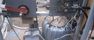
Winding the output choke
One of the simplest and at the same time most useful additions to a welding inverter will be the winding of an inductive coil that smoothes out the DC ripples that inevitably remain when the pulse transformer is operating. The main specificity of this idea is that the choke is made individually for each individual device, and can also be adjusted over time as electronic components degrade or when the power threshold changes.
To make a choke you will need nothing at all: an insulated copper conductor with a cross-section of up to 20 mm2 and a core, preferably made of ferrite. Either a ferrite ring or an armored transformer core is optimally suited as a magnetic core. If the magnetic core is made of sheet steel, it needs to be drilled in two places with an indentation of about 20–25 mm and tightened with rivets in order to be able to cut the gap without any problems.
The choke begins to work starting from one full turn, but the real result is visible starting from 4–5 turns. During testing, turns should be added until the arc begins to stretch noticeably strongly, preventing separation. When it becomes difficult to cook with separation, you need to remove one turn from the coil and connect a 24 V incandescent lamp in parallel with the choke.
Fine-tuning the throttle is done using a plumber's screw clamp, which can be used to reduce the gap in the core, or a wooden wedge, which can be used to increase this gap. It is necessary to ensure that the lamp burns as bright as possible when igniting the arc. It is recommended to manufacture several chokes to operate in ranges up to 100 A, from 100 to 200 A and more than 200 A.