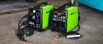
As a result of purchasing a new computer, old power supplies may remain idle, which can be used to create a home workshop. With some effort, you can assemble a welding machine from computer power supplies with your own hands. Such equipment will be useful when performing non-professional tasks of joining metals at home.
The financial investment will not be noticeable, and the time spent on remaking the power source will be fully justified by the appearance of a new type of equipment in the arsenal. We will tell you how to do this work yourself.
Mini spot welding machine with power supply voltage 12V
Hello. In this article I will tell you how to make a simple spot welding machine powered by 12V. Most of the parts needed to assemble the device can be obtained from faulty switching power supplies or boards of old TVs and monitors.
Materials and tools: - breadboard or foil PCB; — ferrite ring; — two field-effect transistors IRF3205 or similar; — two 5.6 kOhm resistors; — two resistors 470 Ohm 2 W; — two zener diodes at 6.2V; — two ultra-fast diodes HER108; — capacitor 0.68 μF; — metal powder ring for the throttle; - winding wire with a diameter of 0.4-0.7 mm; — winding wire with a diameter of 1-1.5 mm; - solder; — rosin (or other flux for soldering radio components); — installation wires; - wire cutters;
In the diagram you can see two diodes D1 and D2, these are ultra-fast diodes, as the name suggests, their difference is a much higher response speed than conventional rectifier diodes. I used HER108 diodes, but they can be replaced with analogues UF1004, UF1007, HER308 or others. When choosing diodes, you should pay attention to such a parameter as the recovery time, this indicator should be less than 100 ns.
You can start assembling the device by winding the transformer. Two ferrite rings M2000NM1-B with dimensions 31x18.5x7 were used as the core.
The number of turns may be less (but preferably at least seven), and the cross-section of the wire depends more on the remaining elements of the circuit. If the inductor in the finished device gets very hot during operation, the cross-section of the wire should be increased and/or the number of turns reduced.
Next, you should proceed to assembling the circuit on the board. It is better to assemble the circuit from the center of the board to the edges. So that already installed parts do not interfere with the installation of subsequent ones.
It is important to remember that the metal substrate of the transistor, to which the radiator is attached, is integral with the drain of the transistor. Therefore, when using a common heatsink for both transistors, it is necessary to install an insulating substrate between the body of the semiconductor device and the heatsink, otherwise a short circuit will occur. Also, even when using separate radiators, you should ensure that the radiator does not come into contact with the tracks on the board or the leads of other elements.
Next, you can proceed to the manufacture of the secondary winding of the transformer. It consists of one turn with three strands of winding wire with a diameter of 1 mm. The output current and voltage depend on the number of turns and cross-section of the wire in the secondary winding. Therefore, I deliberately did not secure the secondary winding with epoxy glue or electrical tape, so that, if necessary, I could easily change the number of turns or cross-section of the wire, changing the output characteristics of the device. Screw terminals are installed on the winding terminals.
How to assemble inverter welding: step-by-step description + (Video)
To assemble an inverter welding machine, you must complete the following work steps:
1) Housing . It is recommended to use an old computer system unit as a housing for welding. It is best suited as it has the required number of holes for ventilation. You can use an old 10-liter canister in which you can cut holes and place the cooler. To increase the strength of the structure, it is necessary to place metal corners from the system housing, which are secured using bolted connections.
2) Assembling the power supply. An important element of the power supply is the transformer. It is recommended to use 7x7 or 8x8 ferrite as the base of the transformer. For the primary winding of the transformer, it is necessary to wind the wire across the entire width of the core. This important feature entails improved operation of the device when voltage surges occur. It is imperative to use PEV-2 copper wires as wire, and if there is no busbar, the wires are connected into one bundle. Fiberglass is used to insulate the primary winding. On top, after the layer of fiberglass, it is necessary to wind turns of shielding wires.
Transformer with primary and secondary windings for creating inverter welding
3) Power part . A step-down transformer acts as a power unit. Two types of cores are used as a core for a step-down transformer: Ш20х208 2000 nm. It is important to provide a gap between both elements, which is solved by placing newsprint. The secondary winding of a transformer is characterized by winding turns in several layers. It is necessary to lay three layers of wires on the secondary winding of the transformer, and fluoroplastic gaskets are installed between them. It is important to place a reinforced insulating layer between the windings, which will avoid voltage breakdown on the secondary winding. It is necessary to install a capacitor with a voltage of at least 1000 Volts.
Transformers for the secondary winding from old TVs
To ensure air circulation between the windings, it is necessary to leave an air gap. A current transformer is assembled on a ferrite core, which is connected to the circuit to the positive line. The core must be wrapped with thermal paper, so it is best to use cash register tape as this paper. Rectifier diodes are attached to the aluminum radiator plate. The outputs of these diodes should be connected with bare wires with a cross-section of 4 mm.
3) Inverter block . The main purpose of an inverter system is to convert direct current into high-frequency alternating current. To ensure an increase in frequency, special field-effect transistors are used. After all, it is the transistors that work to open and close at high frequencies.
It is recommended to use more than one powerful transistor, but it is best to implement a circuit based on 2 less powerful ones. This is necessary in order to be able to stabilize the current frequency. The circuit cannot do without capacitors, which are connected in series and make it possible to solve the following problems:
Read also: How to cut down a thick tree with a chainsaw
Aluminum plate inverter
4) Cooling system . Cooling fans should be installed on the case wall, and for this you can use computer coolers. They are necessary to ensure cooling of the working elements. The more fans you use, the better. In particular, it is imperative to install two fans to blow over the secondary transformer. One cooler will blow on the radiator, thereby preventing overheating of the working elements - rectifier diodes. The diodes are mounted on the radiator as follows, as shown in the photo below.
Rectifier bridge on the cooling radiator
It is recommended to use an auxiliary element such as a temperature sensor.
It is recommended to install it on the heating element itself. This sensor will be triggered when the critical heating temperature of the working element is reached. When it is triggered, the power to the inverter device will be turned off.
Powerful fan for cooling the inverter device
During operation, inverter welding heats up very quickly, so the presence of two powerful coolers is a prerequisite. These coolers or fans are located on the device body so that they work to extract air.
Fresh air will enter the system thanks to the holes in the device body. The system unit already has these holes, and if you use any other material, do not forget to provide a flow of fresh air.
5) Soldering the board is a key factor since the entire circuit is based on the board. It is important to install diodes and transistors on the board in opposite directions to each other. The board is mounted directly between the cooling radiators, with the help of which the entire circuit of electrical appliances is connected. The supply circuit is designed for a voltage of 300 V. The additional arrangement of capacitors with a capacity of 0.15 μF makes it possible to dump excess power back into the circuit. At the output of the transformer there are capacitors and snubbers, with the help of which the overvoltages at the output of the secondary winding are suppressed.
6) Setting up and debugging work . After the inverter welding has been assembled, several more procedures will need to be carried out, in particular, setting up the operation of the unit. To do this, connect a voltage of 15 volts to the PWM (pulse width modulator) and power the cooler. Additionally connected to the relay circuit through resistor R11. The relay is included in the circuit in order to avoid voltage surges in the 220 V network. It is imperative to monitor the relay’s activation, and then apply power to the PWM. As a result, a picture should be observed in which rectangular areas in the PWM diagram should disappear.
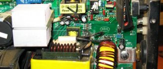
The device of a homemade inverter with a description of the elements
You can judge whether the circuit is connected correctly if the relay outputs 150 mA during setup. If a weak signal is observed, this indicates that the board connection is incorrect. There may be a breakdown in one of the windings, so to eliminate interference you will need to shorten all power supply wires.
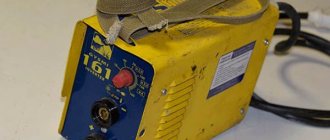
Inverter welding in a computer system case
Checking the device's functionality
After all the assembly and debugging work has been completed, all that remains is to check the functionality of the resulting welding machine. To do this, the device is powered from a 220 V power supply, then high current values are set and the readings are verified using an oscilloscope. In the lower loop, the voltage should be within 500 V, but not more than 550 V. If everything is done correctly with a strict selection of electronics, then the voltage indicator will not exceed 350 V.
So, now you can check the welding in action, for which we use the necessary electrodes and cut the seam until the electrode burns out completely. After this, it is important to monitor the temperature of the transformer. If the transformer simply boils, then the circuit has its shortcomings and it is better not to continue the work process.
After cutting 2-3 seams, the radiators will heat up to a high temperature, so after this it is important to allow them to cool down. To do this, a 2-3 minute pause is enough, as a result of which the temperature will drop to the optimal value.
Checking the welding machine
Making a welding inverter from a computer power supply with your own hands
Currently, not only professionals, but amateur welders work with inverter welding using modern equipment. An inverter is used very often; almost everyone has one.
Do you want to cook, but don’t have the money to buy equipment? Assembling an inverter with your own hands will help solve this problem.
We have already described how to assemble a welding machine using the materials you have at hand on this site. Today we will talk about assembling a welding inverter from a computer power supply. The necessary diagrams are provided in the article.
- Homemade device. Why him?
- Or should I buy it in a store?
- Inverter with power supply Technical characteristics
- Parts that are needed
- Assembly Features
Sine wave
The signal shape at the output of a car inverter is generated by a high-frequency generator. A sine wave can be of two types:
- modified sine wave;
- pure sine wave, pure sine wave.
Not every electrical device can work with a modified sine wave, which has a rectangular shape. Some components change their operating mode, they can heat up and start to get dirty. You can get something similar if you dim an LED lamp whose brightness is not adjustable. The crackling and flashing starts.
Expensive DC AC step-up voltage converters 12V-220V have a pure sine wave output. They cost much more, but electrical appliances work great with it.
Homemade device. Why him?
Is there a need to assemble a welding inverter from a computer power supply with your own hands, if any hardware store can offer a price of up to $50, saving you from suffering? – every craftsman asked himself this question.
This is true. At the same time, everything is not as obvious as it might seem.
The price of 50 dollars is an adventure when buying inverter devices. They are not suitable even for temporary use, let alone permanent use. What is the solution to the problem, you ask.
The cost of high-quality devices starts from $100. Then there is no talk of saving. For most citizens of our country, this amount is equal to half the salary, if not most of it.
For this reason, some are discussing assembling homemade welding inverters from a computer power supply. The cost of which is naturally lower than factory analogues. Everyone can personally choose which functions they need and what they will use to assemble them.
If you don't need a hot start or arc afterburner, there's no point in paying more.
The quality of the ingredients is the second factor to pay attention to. Factories, for the most part, assemble options that are far from high-quality spare parts, which in turn cost more during service repairs.
What you can save on, what parts to assemble the equipment from, you choose yourself.
The opinion of welders about the machine is also important. Not everyone likes modern technology. Some consider them too “sophisticated” and complex. They are not interested in overpaying for the brand and additional features.
You only need functional equipment for everyday use. Then, it is advisable to make a welding inverter from a computer power supply yourself. You can assemble not only a cheap and simple inverter, but one that will make factory equipment the envy of yours.
Everything you need, no extra parts.
Assembly from ready-made blocks
150 watt booster
To assemble a stationary or automotive 12v 220v inverter with your own hands, you can use ready-made blocks that are sold on eBay or from the Chinese. This will save time on board manufacturing, soldering and final setup. It is enough to add a housing and wires with crocodiles to them.
You can also purchase a radio kit, which is equipped with all radio components; all that remains is to solder it.
Approximate price for autumn 2016:
- 300W – 400rub;
- 500W – 700rub;
- 1000W – 1500rub;
- 2000W – 1700rub;
- 3000W - 2500 rub.
Read also: Is it possible to drill a concrete wall with a screwdriver?
To search on Aliexpress, enter the query in the search bar “inverter 220 diy”. The abbreviation "DIY" stands for "do-it-yourself assembly."
500W board, output 160, 220, 380 volts
150W
Inverter 50 Watt
Autoinverter 300W
Or should I buy it in a store?
Naturally, you can give facts why it is not worth assembling a welding inverter with your own hands from just anything. It is necessary not only to stock up on patience and free time.
It is very important to have knowledge of electrical engineering, to understand and distinguish the principles of operation of electrical appliances, and to understand circuits. You can always study these questions if you lack knowledge.
It is enough to set aside a few weeks to read specific literature. There are many videos on the Internet that will help you quickly finish your training, present simple, clear examples and help you assemble a really high-quality welding inverter from a computer power supply.
12-220 Volt converter on a transformer from an old computer power supply
There are many converter circuits on the Internet, but they all have one common problem - the need to manufacture a step-up transformer, and this repels many radio amateurs from assembling such devices.
The 12-220 Volt voltage converter circuit , which is presented below, does not have this problem. A transformer, of course, is also available here, but it was decided to use a ready-made transformer from an outdated at-200 computer power supply
Most of these power supplies were assembled using a push-pull circuit using two transistors MJE1 30 0 5. MJE13007 or similar, which were launched via a small isolation transformer from a master oscillator on a TL494 chip. The output of the converter was connected through a 1 µF capacitor to the primary winding of the output transformer. The problem was that the transformation ratio turned out to be insufficient to obtain enough voltage at the output of the homemade converter to run energy-saving lamps. The simplest solution turned out to be to use an available microcircuit to build voltage converters - VD2, VD7, connected to the “12V” taps of the transformer. The output of the voltage booster circuit is connected to the minus of the diode bridge on VD3. VD6, which made it possible to obtain a voltage of 190 at the load. 220V , sufficient for the normal start-up and glow of fluorescent lamps, powering adapters for a laptop, cell phone or small stationary TV.
The use of power field-effect transistors (MOSFETs) imposes a limitation on the minimum value of triggering pulses - when the pulse amplitude decreases below 10V, the resistance of the open channel of the transistors greatly increases, their heating increases, the efficiency and maximum power in the load decrease. To eliminate the increase in converter losses when the battery is discharged, the circuit uses a “voltage booster” unit to power the microcircuit. When power is applied, voltage is supplied to the microcircuit through diode VD1, and after generation begins, from the “voltage booster” on diodes VD2, VD7, through resistor R3, the value of which is selected within 470 Ohms. 1.5 kOhm, with the expectation that during normal operation the supply voltage of the microcircuit is about 20V. At the same time, even with a deeply discharged battery, the supply voltage of the microcircuit is at least 15V, which completely opens the channels of the field-effect transistors. The losses become so low that even with a converter load of up to 40 W, radiators can be omitted for field-effect transistors. When using a small radiator (aluminum plate 92*30*1.5 mm), the converter power reaches 100. 200 W and depends entirely on the choice of pulse transformer and output field effect transistors.
The circuit can use any available MOSFET transistors with low open-channel resistance. The smaller R DC (on) , the better. Transistors IRFZ24N, IRFZ34N, IRFZ44N, IRFZ46N, IRFZ48N, 2SK2985, etc. are well suited. Diodes VD2. VD7 must be designed for an operating frequency of 100 kHz, an operating voltage of at least 400V and a current of 1. 3A, for which the available FR204 are well suited. FR207, HER204. HER207, FR154. 157, 1N4936. 1N4937, BYT52G, BYT53G, FR304. FR307 etc. You can use common domestic diodes KD226V. KD226D. The permissible spread in the capacitance of electrolytic capacitors is quite large, so the capacitance of capacitor C3 can be from 1000 µF and higher, for a voltage of 16V. Capacitance C5 can be from 4.7 µF and voltage from 300V. Capacitor C1 serves for a “soft” start of the converter and in most cases may not be installed, because it creates a delay in turning on the converter, which is not always desirable. The operating frequency of the generator is determined by the values of resistor R2 and capacitor C2. With a resistor resistance of R2 = 5.1K, the capacitance of the capacitor can be from 1000 to 3300 pF. The optimal frequency for a particular pulse transformer is selected from the condition of obtaining the maximum voltage at the rated load. During setup, resistor R2 can be replaced with a tuning one, and then replaced with a constant one.
To monitor battery discharge up to 11.8 V, the converter can be supplemented with a normal voltage indication unit, which is based on the use of the widely used TL431A .
This precision regulator , sometimes called a controlled zener diode, is often used in TV and monitor power supplies to regulate the output voltage through an optocoupler connected to the power supply driver. The microcircuit contains 3 outputs: anode, cathode and control electrode REF. When the REF input voltage is below 2.50 V, the conductivity between the anode and cathode with reverse voltage polarity is low. With a slight increase in voltage above 2.50 V, the conductivity increases sharply, causing the LED to light up. To indicate normal voltage above 11.8 V, it is necessary to accurately select the divider R1/R2. The resistor ratio should be 3.72 , i.e. if R2 = 10K, then R1 should be equal to 37.2 K. To accurately adjust the threshold, you can turn on a trimming resistor in series with one of the resistors. When using non-lead batteries, the threshold voltage may be different. In this case, the value of one of the resistors is arbitrarily set, for example R2, and R1 is found by the formula: R1= R2 * (Uthr -2.5) / 2.5.
Resistor R3 is designed to exclude LED backlighting due to the flow of a small current between the anode and cathode of the microcircuit when the voltage at the REF pin is below 2.50 V. The device is connected with separate wires directly to the battery terminals.
The appearance and printed circuit board of the device look like this:
The device is assembled on a small printed circuit board measuring about 93 x 38 mm (the author’s version uses a transformer from an at-200 ). When using other elements, the printed circuit board will have to be slightly adjusted. Discharge resistor R4 is connected directly to the output socket. Its resistance can be anything from 200 kOhm to 4.7 mOhm, and the permissible operating voltage must be at least 300V.
Inverter with power supply
Specifications
Resonant - this is exactly the kind of welding inverter from a computer power supply you will be able to assemble by following the instructions in this article. The range of welding currents is 5-120 Amps. Voltage 90V. When using electrodes with a diameter of 2 mm, there is no interruption of work.
However, when working with electrodes with a diameter of 3 mm, they require at least 2 minutes of rest after 10 minutes of continuous work. These figures may vary depending on the ambient temperature.
The weight is no more than two kilograms, so carrying it will be easy. Falling characteristic. The current intensity is adjusted smoothly. The structure includes 4 boards: control unit, main board, power board and capacitors.
From personal experience I can say that for garage and country work, a welding inverter from a computer power supply is excellent.
Parts that are needed
Let's start with the theory. Let us immediately note that the computer unit is not the best thing for a welding machine. The power supply is fundamentally different from the inverter. The unit can be configured to operate as an inverter.
The finished equipment will not be easy to assemble, and its performance will be much lower. Therefore, out of the entire power supply unit, we use only the case. Some things can be bought at radio markets, and some parts can be removed from an old personal computer.
The welding inverter was developed on a popular forum by a person under the nickname Timval, the thread is still very active. This particular scheme is popular because of its simplicity. My version of the welding inverter is designed for a current of only 100 amperes, this is not enough, but for my tasks it is no longer needed.
The circuit is a single-cycle forward inverter with just one IGBT transistor IRG4PC50KD .
The inverter consists of several parts:
- Input rectifier with storage capacitors and soft start system;
- Control systems with a driver based on a complementary pair of composite transistors of medium power;
- The power part consists of an IGBT transistor and a transformer;
- The output part, consisting of a choke with a rectifier.
KBPC3510 input diode bridge
and is smoothed out by capacious electrolytes.
It is important to note that at the initial moment of time the power is not supplied directly, but through the ballast resistor R12, this is necessary for smooth charging of the capacitors, otherwise the surge current can damage the input diode bridge and knock out the machines.
At the same time, power from the capacitors through another ballast resistor R11 is supplied to the power line of the PWM chip.
The heart of the circuit is the UC3844 ,
which operates at a frequency of about 30 kHz, the signal from the microcircuit first goes to the driver, made on transistors VT2 and VT3, and then to the power transistor VT4.
The voltage on the capacitors increases, so does the power supply to the microcircuit, and as soon as it reaches the threshold value, for the UC3844 it is about 16 volts, the microcircuit will begin to generate control pulses, which will lead to the start of the entire inverter.
Voltage will appear in the secondary windings of the transformer, this will cause the power relay K1 to operate and close the ballast resistor R12 with its contacts, and the mains voltage will be supplied directly to the circuit. The planned launch lasts only a couple of seconds. After a smooth start, the inverter will operate normally. The output voltage of the inverter is about 60 volts, this is enough for normal arc ignition.
If you rotate the current limiting regulator (resistor R3) during welding, the feedback system will immediately work (a circuit consisting of a current transformer CT, diodes VD2-VD4, resistors R5 and R7, capacitor C4).
The current transformer is wound on a small toroidal ferrite core; it has two windings, the primary - just one turn and the secondary.
The power transformer is made on an EPCOS E55/28/25 ferrite core No. 87.
The core was without a frame, so I had to make it myself from mteklotextolite.
The transformer has 4 windings:
- network;
- secondary power;
- fixing;
- self-powering winding for the control system.
In my version, the self-powering winding is not used; instead, a small 24-volt switching power supply with a current of 1-1.5 Amperes is used.
The beginnings of all windings in the diagram are indicated by dots; I advise you to mark the beginning of the winding, for example, by putting red heat shrink on the winding, so that later you don’t have to guess where the beginnings and where the ends of the windings are.
At the very beginning, the network winding is wound, but not completely, but in parts. In my case, a wire with a diameter of 1.20 mm and 25 turns was used to wind this winding. The wire must be laid evenly, turn to turn.
The winding is then insulated, but before that it is filled with epoxy resin. The resin will fill all voids. Because Due to strong magnetic fields, vibrations will form in the transformer and the wire insulation may suffer over time, and with resin the winding will be completely motionless.
We put insulation with Kapton heat-resistant tape and wind the rest of the primary winding. The number of turns, wire and winding direction are the same.
Again we fill everything with resin and put insulation on top. Later, on the board, the ends of these windings are connected in parallel.
Then we wind the fixing winding, the wire diameter is 0.5 mm. The number of turns is 25-26, that is, the same as in the case of the primary winding. This winding is wound so that the wire falls between the turns of the primary winding. The fixing winding is evenly stretched throughout the frame. We do the same with this winding, resin, insulation. By the way, earlier I installed insulation in 2-3 layers, but after winding the fixing winding, more serious insulation is needed, 4-5 layers.
And finally, the power winding, the most labor-intensive. It can be wound with a copper busbar or, even better, with tape. Litz wire works most effectively - a wire that consists of a large number of parallel thin wires insulated from each other; such winding is done to minimize the influence of the skin effect. But at frequencies of 30 kHz, this effect is not so noticeable, so if you really want, you can take a couple of copper wires of large diameter, but such a wire is very difficult to lay, so I chose Litz wire.
The winding consists of 100 parallel strands of 0.5 mm wire. We twist the whole thing with a drill and cover it with additional insulation, again Kapton tape.
The number of turns is only 9, according to calculations this is enough for the inverter’s no-load voltage to be around 60 volts. After winding, it should also be filled with resin.
The circuit is single-ended and a non-magnetic gap is needed between the halves of the core. In my case, to obtain the required clearance, gaskets were installed under all the cores, a regular receipt from an ATM.
Next, the transformer is assembled, the core halves are securely pulled together, you can even glue them.
Current transformer. Ferrite ring, permeability can be from 1500 to 3000. The dimensions of my ring are R18x8x6. It is important that it be ferrite; similar rings can be found in some switching power supplies; they are located at the input as a choke and usually have two windings. Yellow-white, green-blue rings will not work, the material is different.
First, the core is insulated, in my case with Captnon tape, then the secondary winding is wound. The wire is in varnish insulation, the diameter can be from 0.25 to 0.5 mm. The number of turns in my case is 76.
Next, the winding needs to be insulated; you can simply fill it with epoxy resin. The primary winding is one turn of two parallel strands of 1.20 mm wire going to the power transformer.
The output rectifier is classic for this topology. There are two diodes, a direct one and a short-circuiting one, and the short-circuiting one needs a more powerful one, but you don’t have to worry about it and just plug in two diodes of the 150EBU04 type for 150 amperes with a reverse voltage of 400 volts. Diodes from this line are usually used in welding inverters. Ultra fast diodes are a must. You can use STTH20003 diode assemblies.
Each case contains two ultra-fast diodes independent of each other, each rated at 100 Amps with a reverse voltage of 300 volts. They are even better than 150EBU04 because... their substrate area is much larger and thicker. The connection is screw, which is very convenient.
Throttle. Here everything is not so simple and in fact the choke is quite critical. The greater its inductance, the better the arc will ignite even at low currents. According to the circuit, the inductor is 40 µH, it will be enough, but I got reliable arc ignition at currents of 30 amperes and, in principle, this will be enough.
Honestly, I tried different materials for the inductor - alsifer, unknown rings that are apparently used as a filter in frequency converters, and finally a core made from transformer plates.
The best solution is to use powdered iron cores, they are specially designed to work as a choke, but the ring needs a decent size, and they are not so easy to find and they cost a lot of money. As a result, on the advice of my colleague Timur, who had previously assembled this welder, my choice settled on a package of iron transformer plates.
The trick is that it is virtually impossible to drive the core into saturation, that is, you can increase the inductance and get reliable ignition of the arc at welding currents of at least 5 amperes, I understand that no one cooks at such currents, but still.
The package was assembled from what was available, and in the end the core turned out to have dimensions of 86x30x17mm. I wrapped the plates with Kapton tape, then paper tape and wound the winding. The winding is unfortunately aluminum, but copper is better, but aluminum was available. The winding is wound in three rows, each row has 10-12 turns. After winding each row, the winding was varnished in several layers and insulated with fabric. The final inductance of the inductor is about 80 μH. The disadvantage of such a choke is its large size and weight, but in my case everything turned out quite compact, and I even managed to fix it on the board. The inductor terminals were crimped with tinned copper terminals, the key word is tinned, otherwise such a connection will not work for a long time, it will overheat and oxidize.
Entrance part. The diode bridge was taken ready-made, assembled KBPC3510, bridge rated at 35 amperes, reverse voltage 1000 volts, installed on a radiator.
The power relay in the soft start circuit with a 24 volt coil is designed for a current of 15-30 real amperes; if you plan to use a welder for currents of more than 120 amperes, then it is advisable to use a 30 ampere relay.
Input electrolytic capacitors are 450 volts, in my case there are 2 pieces of 470 μF each, it is advisable to install three, it will not be worse. Select capacitors from a good manufacturer with the lowest possible internal resistance.
It is advisable to take a limiting resistor at the input of 10 watts, a resistance of 10 to 30 ohms.
Diodes VD7, VD8 and VD9 in the converter circuit are needed ultra fast, precisely for the current and voltage specified in the circuit.
I replaced the assembly of capacitors with one, with a capacity of 0.33 μF, a special-purpose capacitor designed for operation in pulse circuits, the kind used in induction heaters. It is highly undesirable to install ordinary film capacitors here.
I have a PWM chip installed on a socket for solderless installation; after complete setup, the chip must be soldered onto the board.
Simply tinning the power paths on the board and strengthening them with solder is not enough; they need to be reinforced with copper wire.
SETTING UP
Be sure to discharge the input capacitors before starting adjustment work!
We first supply 24 volts for control; the mains power is turned off at that moment. We check the signal at the gate of the IGBT transistor, by the way, during setup you can use field-effect transistors, for example, I installed IRF840, it is weak, but you can adjust the circuit. The transistor must be installed on the radiator.
We check the presence of control pulses on the gate of the field switch relative to the supply ground, the pulses should be approximately 45-47% filled, with a frequency of about 30 kHz, if they are, then everything is fine, we move on.
The first start of the circuit is done through a 100-watt incandescent safety lamp. It is advisable to power the control circuit from a separate external 24-volt power source; a laboratory power supply is excellent; moreover, the native power supply system can be excluded; I repeat this only during setup work.
We replace the load resistor in the current feedback circuit with a 10-ohm 1-2 watt one, this is necessary so that it is possible to set up the circuit at low output currents.
We connect the power, that is, we plug the plug into the socket, the lamp will flash for a moment, because The capacitors are initially charged with a sufficiently large current. We check the voltage at the inverter output, it should be about 60 volts, let me remind you that this is the no-load voltage without an output load. We set the current regulator to the minimum position.
We load the inverter, for example, with a nichrome spiral or a light bulb, first give a small load, then gradually increase it until the current limitation is triggered, that is, the duration of the control pulses decreases sharply. Moreover, the circuit must respond to the rotation of the variable resistor, the duration of the pulses must change smoothly depending on the position of the variable resistor slider. If this does not happen, swap the ends of the secondary winding of the current transformer. Next, we change the safety lamp to a more powerful one (about 300 watts).
You can plug in a more powerful field-effect transistor or IGBT, but remember that our circuit is still not fully adjusted. The resistance of the load resistor can be reduced by a factor of two and we repeat the same thing, only at higher currents. You can try the inverter for a short circuit at low current values, at this stage we already understand that we have completed the welding and we can ignite a small arc.
If the current adjustment occurs as normal, then everything is done correctly. We remember that the inverter is without cooling and don’t play around with it for a long time.
Now we need to bring the inverter back to normal. Only at this stage, after the circuit has been fully adjusted, do we install a power IGBT transistor. It is advisable to take cooling radiators from PC processors; they are quite good. I have an output rectifier without an insulating gasket, I have thermal paste. But the radiator with the power transistor and one of the high-speed diodes are located on the second radiator and they must be insulated with a heat-conducting insulating gasket.
The power transformer, inductor and radiators must be securely fixed. It is enough to tighten the transformer and inductor with plastic clamps; you can additionally glue them to the board.
It is advisable to screw the radiators to the board and ensure insulation from each other so that they do not touch under any circumstances during vibrations or falls.
A very important point is cooling, do not skimp on fans, install powerful high-speed ones with large diameters.
A correctly assembled circuit should not make whistles or noises during operation; if there are problems of this kind, most likely the problem is in the transformer, incorrect gap, incorrect number of turns or incorrect phasing.
Let's check the open circuit voltage, we see that it is about 60 volts, and if there is no load, rotating the regulator, the output voltage does not change. The current consumption of the control system at idle from a 24 volt source is only 80 mA, taking into account the current consumption of the relay coil.
We load the inverter to check the current limiting system. The load is a powerful rheostat, the resistance is set to less than half an ohm. The current should be regulated quite smoothly. We set the minimum current and try to ignite the arc. Let's take a two-millimeter electrode and try to cook at currents of about 50-70 Amps.
Video on assembling and setting up a welding inverter:
Sincerely - AKA KASYAN
Welding machine from a computer power supply - a cheap solution for an electrician
Very often, welding work requires an inverter, thanks to which you can get high-quality seams and not take risks when working with gas welding. But purchasing such a device is associated with significant costs, so you can try making a welding machine from a computer power supply. For this you need not only spare parts, wires and a soldering iron. But also skills in electrical engineering, without which you can burn electrical wiring or get an electric shock.
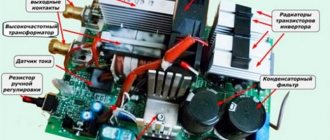
The main components of the welding machine design.
Assembly, installation and subsequent testing can only be carried out if you have experience in rewinding transformers, assembling circuits and creating electrical devices with your own hands. If such knowledge is absent, then it is best to purchase a ready-made inverter and not expose yourself or others to danger.
- Basic installation tools
- Selecting a transformer for a welding machine
- Recommendations for installing other parts of the circuit
- Installing a soldered chip into the case
How to make a charger
Now let's convert the computer power supply into a car charger.
Constant voltage charger
This device charges the battery with a constant fixed voltage of 14 V. As the battery charges, the charging current will drop. As soon as the voltage at the battery terminals reaches 14 V, the current will become zero and charging will stop.
Thanks to this algorithm, the battery cannot be recharged, even if it is left on charge for a week. This is useful when servicing AGM and GEL car batteries that do not like to be recharged.
And now let’s get down to business, especially since the modification scheme is simple. We will modify the ATX power supply on the TL494 controller or its analogues (see the section above). Our task is to increase the output voltage on the +12 V bus to 14 volts. This is not difficult to do. We open the power supply, take out the board and unsolder all the power wires, leaving only yellow, black and green.
We solder the green wire in place of any black one - we issue a command to the power supply unit to unconditionally turn on when connected to the network (see the section above). We unsolder electrolytic smoothing capacitors from all power lines. In the place where the capacitor stood on the +12 V bus, we install a capacitor of the same capacity, but with an operating voltage of 35 V. We proceed to finalizing the controller. We find a resistor that connects the first pin of the microcircuit to the +12 V bus. In the diagram below it is indicated by an arrow.
We need to change its denomination. But which one? We solder it and measure its resistance. In our case, its nominal value is 27 kOhm, but depending on the power supply model, the value may vary. In place of the soldered one, install a variable resistor with a nominal value approximately twice as large. We set the resistor slider to the middle position.
We turn on the power supply and, measuring the voltage on the +12 V bus (yellow wire relative to black), rotate the slider. The voltage is easily reduced, but it cannot be increased - the overvoltage protection interferes. In order to raise the voltage to the 14 V we need, it needs to be turned off. We find a resistor and a diode in the diagram, indicated by arrows in the figure below, and unsolder them.
We turn on the power supply again, set the voltage between the black and yellow wires to 14 V. Turn it off, unsolder the resistor without touching its slider, and measure the resistance. In place of the variable we install a constant of the same denomination. We install two terminals on the case, solder the black and yellow wires to them, mark where the plus and minus are (yellow is plus, black is minus).
We turn on the power supply again, now a device converted into a battery charger. We connect the load to the terminals - the high beam lamp of the car. We measure the voltage at the terminals: if it has not decreased by more than 0.2 V, then the modification is complete. We assemble the device and use it.
Important! The final charging voltage for AGM and GEL batteries is 13.8 V, so it makes sense to reduce the output voltage from 14 V to 13.8 V.
Perhaps the only drawback of this homemade design is that it does not have protection against short circuits and reverse polarity (we turned it off). Therefore, you need to use the device carefully.
Basic installation tools
If you have experience and knowledge in the field of electrical engineering, then you can explore several options on how to make a welding machine from a computer unit. Basic tools that will be needed for all types of assembly:
- soldering iron or soldering station;
- tester;
- multimeter;
- electrical insulating tape;
- solder;
- screwdrivers with different tips;
- pliers;
- screws;
- screwdriver or drill;
- crocodiles;
- wires of the required cross-section.
To recreate the circuit of the welding machine, you will need all the spare parts indicated in the circuit, getinaks and solutions for transferring the printed circuit board to the workpiece.
To make your work easier, you can purchase an electrode holder and welding cables at the store. You can do it yourself by selecting wires of the appropriate cross-section and soldering crocodiles to them, remembering to observe the polarity.
Welding inverter circuit.
If you have a non-working computer system unit, then you need to remove the main battery from it and prepare it for dismantling. Sometimes, to create a powerful welding machine, they even use the system unit itself, installing wheels on it at the bottom and increasing the number of ventilation holes. The advantage of computer cases is that they are lightweight, easy to cool and already have ventilation.
The welding machine will require disassembling the power supply.
The main things that can be used from it are the fan, the housing itself and some spare parts. But it all depends on the modes in which the cooling operates. The fan must be checked for functionality and tested in several modes. It is advisable to install another one of the same or more powerful so that the welding machine does not overheat. To monitor the temperature of the inverter, you need to install a thermocouple.
But first you need to take care of the handle, which will make the welding machine from a computer power supply convenient to use. To do this, you need to remove all the spare parts from the power supply and attach a handle selected for size and convenience to the upper end. You need to drill holes in the power supply and secure it with screws, which must be correctly selected in length (too long ones will interfere with the internal circuit, which is unacceptable).
The welding machine must have very good cooling, so several additional holes need to be drilled in the power supply housing.
The duration of operation of a homemade inverter will depend on the quality of ventilation.
The procedure for assembling the welding machine
First of all, to create a welding machine from a computer power supply, you need to remove the power source from the computer case and disassemble it. The main elements that can be used from it are a few spare parts, a fan and standard case plates. It is important to take into account the cooling operating mode. This determines what elements need to be added to ensure the necessary ventilation.
Diagram of a transformer with primary and secondary windings.
The operation of a standard fan, which will cool the future welding machine from a computer unit, must be tested in several modes. This check will ensure the functionality of the element. To prevent the welding machine from overheating during operation, you can install an additional, more powerful cooling source.
To control the required temperature, a thermocouple should be installed. The optimal temperature for operating the welding machine should not exceed 72-75°C.
But first of all, you should install a handle of the required size on the welding machine from a computer power supply for carrying and ease of use. The handle is installed on the top panel of the block using screws.
It is important to choose screws that are optimal in length, otherwise too large ones may affect the internal circuit, which is unacceptable. At this stage of work, you should worry about good ventilation of the device. The placement of elements inside the power supply is very dense, so a large number of through holes should be arranged in it in advance. They are performed with a drill or screwdriver.
Next, you can use multiple transformers to create an inverter circuit. Typically, 3 transformers such as ETD59, E20 and Kx20x10x5 are chosen. You can find them in almost any radio electronics store. And if you already have experience creating transformers yourself, then it’s easier to do them yourself, focusing on the number of turns and the performance characteristics of the transformers. Finding such information on the Internet will not be difficult. You may need a current transformer K17x6x5.
Methods for connecting a welding inverter.
It is best to make homemade transformers from getinax coils; the winding will be enamel wire with a cross-section of 1.5 or 2 mm. You can use 0.3x40 mm copper sheet, after wrapping it in durable paper. Thermal paper from a cash register (0.05 mm) is suitable; it is durable and does not tear so much. The crimping should be done from wooden blocks, after which the entire structure should be filled with “epoxy” or varnished.
When creating a welding machine from a computer unit, you can use a transformer from a microwave oven or old monitors, not forgetting to change the number of turns of the winding. For this work, it would be useful to use electrical engineering literature.
As a radiator, you can use PIV, previously cut into 3 parts, or other radiators from old computers. You can purchase them in specialized stores that disassemble and upgrade computers. Such options will pleasantly save time and effort in searching for suitable cooling.
To create a device from a computer power supply, you must use a single-cycle forward quasi-bridge, or “oblique bridge”. This element is one of the main ones in the operation of the welding machine, so it is better not to save on it, but to purchase a new one in the store.
Printed circuit boards can be downloaded on the Internet. This will make recreating the circuit much easier. In the process of creating the board, you will need capacitors, 12-14 pieces, 0.15 microns, 630 volts. They are necessary to block resonant current surges from the transformer. Also, to make such a device from a computer power supply, you will need capacitors C15 or C16 with the brand K78-2 or SVV-81. Transistors and output diodes should be installed on radiators without using additional gaskets.
During operation, you must constantly use a tester and a multimeter to avoid errors and to assemble the circuit faster.
Electrical circuit of a semi-automatic welding machine.
After manufacturing all the necessary parts, they should be placed in the housing and then routed. The temperature on the thermocouple should be set to 70°C: this will protect the entire structure from overheating. After assembly, the welding machine from a computer unit must be pre-tested. Otherwise, if you make a mistake during assembly, you can burn all the main elements, or even get an electric shock.
On the front side, two contact holders and several current regulators should be installed. The device switch in this design will be a standard computer unit toggle switch. The body of the finished device after assembly requires additional strengthening.
Selecting a transformer for a welding machine
For a circuit that will allow you to make a welding machine from a computer power supply, you will need 3 transformers. They can be purchased based on the names - E20, Kx20x10x5 and ETD 59. But it will be easier to wind them yourself, focusing on the number of turns and other information indicated in the diagram. A current transformer K17x6x5 is also required.
Regarding the manufacture of transformers, you only need an enamel wire, and a new f1.5 or f2. There is no way to do without winding on getinax coils, crimping them with wooden blocks and impregnating them with epoxy resin.
To assemble a device from a computer power supply, you can use a transformer from a microwave oven. Since the voltage on the secondary winding is about 2 kV, it is necessary to reduce the number of turns. To do this, you need to make an additional calculation, which can be done using a special online electrician calculator or find a book on electrical engineering with the corresponding section. But for the sake of such savings, changes will have to be made to the existing scheme.
Welding from a computer power supply
- Date: 06/28/2015
- 840
- : 33
A homemade welding machine, when assembled correctly, will perform its job no worse than a factory-made unit.
A welding machine is a technical device designed to connect various types of parts by heating them.
Existing schemes make it possible to assemble devices even from old computer units and televisions. But it is recommended to start such work if you have at least basic skills in working with electrical appliances.
Preparing to assemble the device from a computer power supply
A simple and very effective welding machine can be assembled using an old computer power supply. To assemble such a homemade device you will need the following:
During the assembly of the welding machine, a multimeter will be needed.
- Soldering iron.
- Electrical insulating tape.
- Multimeter.
- Tester.
- Pliers.
- Several screwdrivers (flathead, Phillips).
- Solder.
- A screwdriver or a drill with a screwdriver function.
- Screws.
- Alligator clips.
- Wires of suitable cross-section.
Such a homemade device will be assembled using a case and some spare parts from a computer power supply. Cooling is very important. Test the fan in several modes. It must be of sufficiently high power. A thermocouple must be installed.
The most convenient handle for the operator is attached to the upper end of the power supply. For fastening, use screws of sufficient length. It is important that they do not reach the internal circuit.
Drill several additional holes in the case for more efficient cooling of the device. The quality of ventilation directly affects how long the future welding machine can operate.
Figure 1. Transformer diagram.
The scheme involves the use of three transformers. The transformer diagram can be found in Figure 1. Transformers of the ETD 59, E20 and Kx20x10x5 series are suitable. You can wind them yourself. Additionally, you will need a current transformer. Usually the product of the K17x6x5 series is used.
To make your own transformer, use a new enamel wire f1.5 or f2. Winding is carried out on getinax coils, crimping with wooden blocks, and impregnation with epoxy resin.
A transformer from a microwave oven is also suitable, but you need to reduce the number of turns of the secondary winding. This requires additional calculations to be performed in advance. This is a more economical option, but it requires significantly more effort and time. In practice, it is much easier to buy a ready-made transformer.
Step-by-step instructions for assembling the welding unit
When assembling the welding machine, it is recommended to install 150ebu02 diodes.
The circuit based on a computer power supply has been tested by more than a dozen welders. Such homemade welding machines require replacing 15tb60 diodes with 25tb60 diodes. In practice, it has been found that this improves the performance of the unit. Diodes 150ebu02 need to be installed in groups of 2.
For additional savings, you can cut the PIV into 3 parts and use this design instead of a radiator. The design necessarily includes a forward-flow single-ended quasi-bridge converter. It is also known as the “oblique bridge”. It is recommended not to skimp on this element. It is better to buy a new high quality part.
During the process, you will need a tester and a multimeter. They will allow you to assemble the circuit as accurately as possible and in the shortest possible time. A homemade device can be connected to the network only after preliminary testing.
Output diodes and transistors are installed on radiators without the use of additional gaskets. Overheat protection should be set to 70 degrees. You can do this using a thermocouple.
After connecting all the parts into one structure, place them inside the housing and perform the correct wiring. The toggle switch for turning on the unit will serve as a switch for the future welding unit. The contact holders and current regulator should be placed on the front panel. The housing must be secured as firmly and carefully as possible.
The manufacture of such a welding machine does not require a lot of money, but it does require effort and time. If you wish and have the necessary skills, you can make individual changes to the circuit and get a welding machine with the characteristics you need.
Homemade resistance welding machine
Figure 2. Diagram of the electronic unit for resistance welding.
A welding machine of this type will help you connect a wide variety of metal products. Current passes through the junction, which leads to its deformation. There are spot, butt and seam methods of such welding.
Before starting to manufacture such a unit, choose the type that suits you best. The contact welding machine can be made stationary, suspended or mobile. Most often, such units are used for welding wires and various pipes. But you can adapt it to connect almost any product. The circuit diagram of the electronic unit of such a device is shown in Figure 2.
Take into account the fact that such a welding machine consumes a lot of electricity when operating. It can be used for welding parts with a thickness of 0.09-0.9 mm. It consists of 2 main elements: a power supply unit, which includes a transformer and a relay, and a gun.
An electrode is connected to the first winding via a cable. During welding, the second terminal must be connected to the product being welded. The welding gun consists of 2 elements of the same size and shape. You can use getinax, textolite and other insulators. To assemble such a welding machine, you will need:
Transformer design.
- Transformer.
- Tester.
- Several screwdrivers.
- Power unit.
- Adapter.
- Lamp.
- Cable.
- Lock nut.
A small switch, lamp holder and adapter are attached to the front. You need to place a backlight switch at the back. The cover is connected with screws. The welding cable is connected to the adapter.
During the assembly process, you need to take into account the dimensions of the selected power supply and transformer. An important characteristic of a transformer is the cross-sectional area of the magnetic core. It must exceed 60 cm².
The primary winding is made with 160-165 turns. It must be placed on one side of the magnetic circuit. Insulation is carried out using wooden wedges. It is necessary to create a bend on the secondary winding. This is done using loops. The bend will make it possible to fix the welding cable using special bolts.
The layers of the primary winding are insulated with fluoroplastic or electrical tape. Tape is used for fixation. The magnetic core must be tightened with corners and M8 bolts. To straighten the plate, a tie is performed. The frame is fixed using wooden wedges.
The auxiliary transformer will provide a voltage of 6-15 V on the second winding. For its manufacture, a magnetic circuit of 1 cm² is used. The windings between the magnetic core must be insulated with tape.
Do-it-yourself full-fledged inverter welding machine
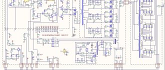
Figure 3. Schematic diagram of a welding inverter.
The design features of the welding inverter make it possible to significantly reduce the dimensions and weight of this unit. There are many models available for sale with different characteristics that allow you to perform a wide range of tasks. But if you don’t want to spend money on buying a ready-made unit, you can assemble it yourself. You just need to understand the operating features and operating principles of the main internal circuits and elements. A schematic diagram of a standard inverter can be found in Figure 3.
Recommendations for installing other parts of the circuit
Due to the fact that this circuit has already been repeatedly used to assemble a welder that has become a replacement for an inverter, there are some comments about it. It is recommended to replace 15tb60 diodes with 25tv60, and it is best to install 150ebu02 diodes in groups of 2.
To save money on the radiator, you can take the PIV and cut it into 3 parts. It is mandatory to use a converter - a single-cycle forward-flow quasi-bridge. Or, more simply, an “oblique bridge”, without which not a single inverter can be assembled. It’s better not to skimp on this spare part and buy a good quality one, not a used one.
Installing a soldered chip into the case
After all the necessary parts have been manufactured and assembled into a single whole, you need to place them in the housing and make the correct wiring. The power supply on/off switch is used as a switch for the future device. On the front panel you need to provide a current regulator and contact holders for connecting welding wires. The housing must be carefully and firmly secured. The end result should be a product that looks something like this.
Such production of a welding machine will allow significant savings, but will require a lot of effort. But after successfully assembling the first inverter, it will be possible to make changes to the circuit, invent your own models (more powerful or lighter) and make such custom-made devices familiar. And this can be a great way to earn extra money.
Making a welding inverter from a computer power supply
As a result of purchasing a new computer, old power supplies may remain idle, which can be used to create a home workshop. With some effort, you can assemble a welding machine from computer power supplies with your own hands. Such equipment will be useful when performing non-professional tasks of joining metals at home.
The financial investment will not be noticeable, and the time spent on remaking the power source will be fully justified by the appearance of a new type of equipment in the arsenal. We will tell you how to do this work yourself.
Converting an ATX power supply into a regulated or laboratory power supply
Now is the time to make a switching laboratory power supply from a computer power supply with your own hands. We will be modifying the power supply, the PWM controller of which is assembled on a specialized TL494 microcircuit (aka: μA494, μPC494, M5T494P, KIA494, UTC51494, AZ494AP, KA7500, IR3M02, AZ7500BP, KR1114EU4, MV3759 and similar analogues).
Expert opinion
Alexey Bartosh
Specialist in repair and maintenance of electrical equipment and industrial electronics.
Ask a Question
Let's make a reservation right away - although the typical connection circuits for these microcircuits are the same, there are still some differences depending on the power supply model. Therefore, there is no universal solution for remaking all power supplies.
For example, we will modify the power supply, the diagram of which is shown below. Having understood the idea of the changes being made, choosing an algorithm for remaking any other block will not be difficult.
We disassemble the power supply and remove the board. Immediately unsolder all unnecessary wires of the power cables, leaving one yellow, one black and green.
We also solder smoothing electrolytic capacitors along all power lines. In the diagram they are designated as C30, C27, C29, C28, C35. We are going to significantly (up to 25 V on the +12 V bus) increase the output voltage, for which these capacitors are not designed. In place of the one that stood on the +12 V bus, we install a capacitor of the same or larger capacity for a voltage of at least 35 V. We leave the remaining places empty. We solder the green wire in place where any black wire was to allow the power supply to start. Now you can start modifying the controller.
Let's take a look at the pin assignments of the TL494 chip. We are interested in two nodes - error amplifier 1 and error amplifier 2. The first contains a voltage stabilizer, and the second contains a current controller. That is, we are interested in the wiring of pins 1, 2, 3, 4, 13, 14, 15, 16.
Let's change the wiring diagram so that error amplifier 1 is responsible for adjusting the output voltage, and amplifier 2 is responsible for adjusting the current. First of all, we will cut the paths indicated by crosses in the diagram below.
Now we find resistors R17 and R18. The first has a resistance of 2.15 kOhm, the second 27 kOhm. We change them to nominal values of 1.2 kOhm and 47 kOhm, respectively. We add two variable resistors to the circuit, one constant at 10 kOhm (marked in green), terminals for connecting an external consumer, an ammeter and a voltmeter. As a result, we will get a diagram like this.
As can be seen from the diagram, a 22 kOhm resistor allows you to smoothly regulate the voltage within 3-24 V, a 330 Ohm resistor allows the current to vary from 0 to 8 A. Cl1 and Cl2 are used to connect the load. A voltmeter has a measurement limit of 25-30 V, an ammeter - 10 A. The devices can be either pointer or with digital scales, most importantly, small-sized - after all, they must fit into the power supply housing. You can begin checking and calibrating.
Expert opinion
Alexey Bartosh
Specialist in repair and maintenance of electrical equipment and industrial electronics.
Ask a Question
We first turn on our laboratory power supply through a 220 V incandescent lamp with a power of 60 W. This will help avoid problems if we made mistakes in installation. If the lamp does not glow or glows at full intensity, and the power supply starts up, then everything is in order. If the lamp is on at full intensity and the power supply is silent, then you will have to look for errors.
Everything is fine? We connect the power supply directly to the network, and move the resistor sliders to the lowest position according to the diagram. We connect a load to terminals KL1, KL2 - 2 high beam lamps connected in series. We rotate the voltage adjustment resistor and check with the built-in voltmeter that the voltage changes smoothly from 3 to 24 volts. To be sure, we connect a control voltmeter, for example, a tester, to the terminals. We calibrate the voltage regulator knob, guided by instrument readings.
We return the engine to the bottom position according to the diagram, turn off the power supply, and connect the lamps in parallel. Turn on the power supply, set the current regulator to the middle position, and the voltage regulator to 12 V. Rotate the current regulator knob. In this case, the ammeter readings should smoothly change from 0 to 8 A, and the lamps should smoothly change brightness. We calibrate the current regulator based on the ammeter readings.
Disconnect the device and assemble it. Our laboratory power supply is ready. With its help, we can get any voltage from 3 to 24 volts and set the current limit through the load in the range of 0-10 A.
Required parts and equipment
Inverter welding machines are complex electronic devices that are not possible to assemble independently without certain qualifications and the availability of the necessary equipment. Therefore, you will have to rent expensive equipment while debugging and assembling the unit.
You should start creating a welding machine from a computer power supply by selecting a suitable and simple electrical circuit so that the selection of semiconductor and other components does not need to be recalculated. Low-power inverter units consume a current of no more than 15 A from the network.
The network cable can be saved, but the fan must be replaced with a more powerful one, which will ensure good cooling of the radiators of the power elements. In addition, you will need the following tools and equipment:
- foil PCB for boards or its substitutes;
- wires of the required cross-section and length;
- semiconductor elements, resistances and capacitors of the required value, according to the selected circuit;
- a transformer with suitable characteristics, which may have to be adapted to the required parameters;
- radiators for power elements;
- soldering iron with solder and rosin or flux;
- screwdrivers, pliers, fasteners, drill and insulating material;
- multimeter, oscilloscope.
It is extremely important to carry out installation in strict accordance with the selected circuit, observing polarity and checking for leaks.
What does an inverter welding circuit look like?
In order to understand what an inverter welding machine is, it is necessary to consider the diagram presented below.
Electrical circuit of inverter welding
All these components must be combined and thereby obtain a welding machine, which will be an indispensable assistant when performing plumbing work. Below is a schematic diagram of inverter welding.
Inverter welding power supply diagram
The board on which the device's power supply is located is mounted separately from the power section. The separator between the power part and the power supply is a metal sheet connected electrically to the unit body.
To control the gates, conductors are used, which must be soldered close to the transistors. These conductors are connected to each other in pairs, and the cross-section of these conductors does not play a special role. The only thing that is important to consider is the length of the conductors, which should not exceed 15 cm.
For a person who is not familiar with the basics of electronics, reading this kind of circuit is problematic, not to mention the purpose of each element. Therefore, if you do not have skills in working with electronics, then it is better to ask a familiar specialist to help you figure it out. For example, below is a diagram of the power part of an inverter welding machine.
Diagram of the power part of inverter welding
Inverter assembly sequence
When preparing for the final assembly of the inverter, you need to take care of the presence of a temperature sensor designed to operate when heated from 70 to 75 o C. In addition, you need to take care of the sockets for the power cable and the electrode holder with wires with a cross-section of 35 mm 2, for efficient supply of current to the welding machine. arcs. Then, having prepared all the necessary elements, we begin installation in the following sequence:
- we position the fan and cooling radiators so as to ensure the most efficient air flow, and provide reliable fastening;
- securely fasten the transformer and capacitor board;
- install the control circuit board and related parts;
- we install an anti-stick and hot start device;
- we check for short circuits the contacts through which the circuit components are powered;
- We carry out final wiring and installation of fuses and thermoelements;
- We carry out the final adjustment using a multimeter and an oscilloscope, taking into account the calculated parameters;
- We set the required welding current and carry out trial work.
How to make a welding inverter from a computer power supply with your own hands?
A DIY welding inverter made from a computer power supply is becoming increasingly popular among both professionals and amateur welders. The advantages of such devices are that they are comfortable and lightweight.
Welding inverter device.
The use of an inverter power source allows you to qualitatively improve the characteristics of the welding arc, reduce the size of the power transformer and thereby lighten the weight of the device, makes it possible to make adjustments smoother and reduce spatter during welding. The disadvantage of an inverter-type welding machine is its significantly higher price than its transformer counterpart.
In order not to overpay large sums of money in stores for welding, you can make a welding inverter with your own hands. To do this, you need a working computer power supply, several electrical measuring instruments, tools, basic knowledge and practical skills in electrical work. It would also be useful to acquire relevant literature.
If you are not confident in your abilities, then you should go to the store for a ready-made welding machine, otherwise, with the slightest mistake during the assembly process, there is a risk of getting an electric shock or burning all the electrical wiring. But if you have experience in assembling circuits, rewinding transformers and creating electrical appliances with your own hands, you can safely begin the assembly.
Improved heat dissipation
The first drawback that plagues the vast majority of inexpensive inverter devices is a poor heat removal system from power switches and rectifier diodes. It is better to begin improvements in this direction by increasing the intensity of forced airflow. As a rule, case fans are installed in welding machines, powered by 12 V service circuits. In “compact” models, forced air cooling may be completely absent, which is certainly nonsense for electrical equipment of this class.
Read also: Steel 9xs or r6m5
It is enough to simply increase the air flow by installing several of these fans in series. The problem is that the “original” cooler will most likely have to be removed. To operate effectively in a sequential assembly, fans must have an identical shape and number of blades, as well as rotation speed. Assembling identical coolers into a “stack” is extremely simple; just tighten them with a pair of long bolts along diametrically opposite corner holes. Also, do not worry about the power of the service power supply; as a rule, it is enough to install 3–4 fans.
If there is not enough space inside the inverter housing to install fans, you can install one high on the outside. Its installation is simpler because it does not require connection to internal circuits; power is removed from the power button terminals. The fan, of course, must be installed opposite the ventilation louvers, some of which can be cut out to reduce aerodynamic drag. The optimal direction of air flow is towards the exhaust from the housing.
The second way to improve heat dissipation is to replace standard aluminum radiators with more efficient ones. A new radiator should be selected with the largest number of fins as thin as possible, that is, with the largest area of contact with air. It is optimal to use computer CPU cooling radiators for these purposes. The process of replacing radiators is quite simple, just follow a few simple rules:
- If the standard radiator is isolated from the flanges of the radio elements with mica or rubber gaskets, they must be preserved when replacing.
- To improve thermal contact, you need to use silicone thermal paste.
- If the radiator needs to be trimmed to fit into the case, the cut fins must be carefully processed with a file to remove all burrs, otherwise dust will accumulate on them abundantly.
- The radiator must be pressed tightly against the microcircuits, so you first need to mark and drill mounting holes on it; you may need to cut a thread in the body of the aluminum base.
Additionally, we note that there is no point in changing the piece heatsinks of separate keys; only the heat sinks of integrated circuits or several high-power transistors installed in a row are replaced.
Operating principle of inverter welding
Schematic diagram of the inverter.
The welding inverter consists of a power transformer that reduces the network voltage, stabilizer chokes that reduce current ripple, and an electrical circuit block. MOSFET or IGBT transistors can be used for the circuits.
The principle of operation of the inverter is as follows: alternating current from the network is sent to the rectifier, after which the power module converts direct current into alternating current with increasing frequency. Next, the current enters the high-frequency transformer, and the output from it is the welding arc current.
Voltage converter design
Let's consider the design of a conventional step-up voltage converter from 12 to 220. The operating principle for all modern inverters will be the same. The high-frequency PWM controller sets the operating mode, frequency and amplitude. The power part is made of powerful transistors, the heat from which is transferred to the device body.
At the input of the converter from 12 to 220 there is a fuse that protects the car battery from short circuits. A thermal sensor is attached next to the transistors, which monitors their heating. If the 12v-220v inverter overheats, an active cooling system consisting of one or more fans is turned on. In budget models, the fan can work constantly, and not just under high load.
Power transistors at the output
Tools required to make an inverter
To assemble a welding inverter from a power supply with your own hands, you will need the following tools:
TL494 voltage feedback circuit in a computer power supply.
- soldering iron;
- screwdrivers with different tips;
- pliers;
- wire cutters;
- drill or screwdriver;
- crocodiles;
- wires of the required cross-section;
- tester;
- multimeter;
- consumables (wires, solder for soldering, electrical tape, screws and others).
To create a welding machine from a computer power supply, you need materials to create a printed circuit board, getinaks, and spare parts. To reduce the amount of work, you should go to the store for ready-made electrode holders. However, you can make them yourself by soldering crocodiles to wires of the required diameter. It is important to observe polarity when doing this work.
Power converter circuits
A powerful inverter is mainly used to connect construction power tools during the construction of a summer house or hacienda. A low-power 500-watt voltage converter differs from a powerful 5,000-10,000-watt converter in the number of transformers and power transistors at the output. Therefore, the manufacturing complexity and price are almost the same; transistors are inexpensive. The power is optimally 3000 W, you can connect a drill, grinder and other tools.
I will show several inverter circuits from 12, 24, 36 to 220V. It is not recommended to install these in a passenger car; you can accidentally damage the electrics. The circuit design of DC AC converters 12 to 220 is simple, a master oscillator and a power section. The generator is made on the popular TL494 or analogues.
A large number of booster circuits from 12v to 220v for making with your own hands can be found at the link https://cxema.my1.ru/publ/istochniki_pitanija/preobrazovateli_naprjazhenija/101-4 In total there are about 140 circuits, half of them are boost converters with 12, 24 at 220V. Powers from 50 to 5000 W.
After assembly, you will need to adjust the entire circuit using an oscilloscope; it is advisable to have experience working with high-voltage circuits.
To assemble a powerful 2500 Watt inverter you will need 16 transistors and 4 suitable transformers. The cost of the product will be considerable, comparable to the cost of a similar radio designer. The advantage of such costs will be a pure sine output.
Sergey, hello! I have a question: I have a DC12->AC220 converter for 300W, I power my computer with it. Everything works fine for about 1-2 hours (consumption is approximately 120W). But when the converter lacks energy, it makes a wild squeak and immediately abruptly cuts off the output. At the same time, approximately 11.5 volts remain in the battery. The converter is Chinese, but in appearance it is quite good. The question itself is: why does this happen if there is still a lot of energy in the battery and how to improve this so that the converter sucks out at least half the energy. Ideally, it would also squeak a little before dying.