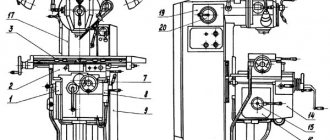
Kinematic diagram of gear hobbing machine 5k324
Kinematic diagram of gear hobbing machine 5k324
Movements in the machine. The main movement is the rotation of the cutter. Feeds: vertical - calipers 3, radial - table 5. Dividing rotation of the table and workpieces. Accelerated movements: caliper, table, cutter movement, table rotation 4.
When processing spur wheels in the machine, the following movements must be carried out: main movement, vertical feed of the caliper, rotation of the table and installation movements of the caliper. In automatic cycles, in addition, radial feed and installation movements of the table are performed. When processing helical wheels, additional rotation of the table is necessary to process the teeth located along the helical line.
When processing worm wheels using the radial feed method, the machine performs: main movement, radial feed and installation movements of the table.
For cutting spur gears, the machine is equipped with the following kinematic chains:
- Main rotational movement of the cutter
- Dividing, coordinating the rotational movements of the hob cutter and the wheel being cut
- Vertical Feed Hob Cutter
Information about the manufacturer of the vertical gear hobbing semi-automatic machine 5K32A
Manufacturer of the vertical gear hobbing semi-automatic machine 5K32A Yegoryevsky Machine Tool Plant Komsomolets , founded in 1930.
During its existence, the plant has produced over 60 models: gear hobbing, gear shaping, gear grinding, gear rounding and other gear processing machines.
Products of the Yegoryevsk Machine Tool Plant Komsomolets, SZK
- 5A12
- semi-automatic vertical gear shaping machine Ø 208 - 5A140P
- semi-automatic vertical gear shaping machine Ø 500 - 5B150
– semi-automatic vertical gear shaping machine Ø 800 - 5B833
- vertical gear grinding machine for cylindrical gears Ø 200 - 5D32
- vertical gear hobbing machine for cylindrical gears Ø 800 - 5E32
- vertical gear hobbing machine for cylindrical gears Ø 800 - 5K32
- vertical gear hobbing machine for cylindrical gears Ø 800 - 5K32A, 5K324A
- vertical gear hobbing machine for cylindrical gears Ø 800 - 5K324
- vertical gear hobbing machine for cylindrical gears Ø 500 - 5K328A
- vertical gear hobbing machine for cylindrical gears Ø 1250 - 53A11
- vertical gear hobbing machine for cylindrical gears Ø 1250 - 53A50
- vertical gear hobbing machine for cylindrical gears Ø 500 - 53A80
- vertical gear hobbing machine for cylindrical gears Ø 800 - 514
— semi-automatic vertical gear shaping machine Ø 500 - 532
— vertical gear hobbing machine for cylindrical gears Ø 750 - 5310
— vertical gear hobbing machine for cylindrical gears Ø 200
Common equipment models
The 5M14 gear cutting machine, the design of which we examined in the previous section of the article, was one of the most popular slotting units during the USSR, and it is used in the engineering industry to this day.
In the basic configuration, the 5M14 gear shaping machine can cut spur gears of the cylindrical type, however, the equipment manufactured to special order was equipped with screw guides that allow cutting screw teeth.
Gear cutting machine 5M14
Let's look at the technical characteristics of this unit:
- diameters of processed wheels - from 20 to 500 mm;
- maximum width of cut teeth: with external gearing - 105 mm, with internal gearing - 75 mm;
- range of cut modules - from 2 to 6 mm;
- tooth angle - up to 23 degrees;
- stroke stroke - up to 125 mm;
- maximum longitudinal movement of the caliper - 50 mm;
- spindle-table distance – up to 350 mm;
- the number of double strokes of the cutter is 400, 265, 179 and 124 mm.
5M14 is equipped with a 2800 W electric drive. This model is a large-sized stationary equipment with dimensions of 180*135*220 cm and a weight of 3.5 tons. As its analogue, we can consider the gear shaping machine 5140, which has similar characteristics and functionality, which differs in the module of the cut wheel increased to 8 mm.
Gear cutting machine 5B12
Among the compact models, we highlight the 5B12 gear cutting machine. Like the units discussed above, it was produced at the Korsun-Shevchenkovsky Machine Tool Plant. This is a high-performance device capable of cutting straight and oblique teeth on cylindrical wheels with internal and external gearing without changing the configuration.
This model is distinguished by its comparative ease of setup, which allows it to be used in small-scale production. The machine is fully automated within the 1st working cycle. Let's look at the functionality of 5B12:
- diameters of processed wheels - from 12 to 208 mm;
- maximum width of cut teeth: for external gearing - 50 mm, for internal gearing - 30 mm;
- range of cut modules - from 2 to 4 mm;
- stroke stroke - up to 50 mm;
- maximum longitudinal movement of the caliper - 50 mm;
- spindle-table distance – up to 140 mm;
- the number of double strokes of the cutter is 600, 425, 315 and 200 mm.
5V12 is equipped with an electric drive with a power of 2200 W. The weight of the machine is 1.95 tons, dimensions are 132*94*182 cm.
Detailed technical characteristics of the semi-automatic gear shaping machine 5B12
Electrical diagram of gear shaping machine 5B12
It may also be useful: Passport 5M150 5M150P 5M161 to menu
Settings Features
Setting up a gear shaping machine consists of the following operations:
- Selection of division and feed gears;
- Selection of radial feed cam.
- Selection of the required drive speed and number of strokes of the cutter.
To determine the number of strokes of the cutter, the formula is used:
- d—cutting speed;
- k is the width of the teeth profile of the workpiece);
- p is the overtravel of the cutter beyond the end of the part.
In this case, the length of the cutter stroke is taken to be no less than the ratio L = k +4 mm. You can calculate replacement wheels for a dividing guitar using the formula:
- O, P, J, L - the number of teeth on the replacement wheels of the guitar;
- d is the actual diameter of the pitch circle of the cutter;
- n is the number of moves calculated in the first formula.
You will also need to calculate the replacement rings for the radial feed guitar, this is done according to the formula: In the formula, M is a non-replaceable coefficient for the machine model used, Yrad is the value of the radial feed of the wheel per 1 stroke of the cutter.
Read also: Calculation of settings and adjustment of semi-automatic gear shaping machine model 514
data-full-width-responsive=”true” data-ad-client=”ca-pub-8514915293567855″data-ad-slot=”8040443333″>
Main technical parameters
This type of machine has a fairly large number of technical characteristics. At the same time, setting up a gear hobbing machine allows you to change some parameters, which allows one panel to be used to produce gears with different parameters.
Gear hobbing machines have the following main technical characteristics:
- Setting up a gear hobbing machine taking into account the diameter of the crown and the maximum size of the tooth module
- An important indicator is the width of the ring gear.
- By calculating the differential pattern of a gear hobbing machine, you can set the processing mode when cutting teeth at an angle. In this case, the angle can be set within a certain range.
- Considering the universal gear hobbing machine, we note that the design has a support that moves in the vertical and transverse direction. An important point is the maximum movement rate.
- The classic device of a gear hobbing machine has a unit in which the cutting tool is fastened. Manual setting or installed CNC systems for gear hobbing machines can set the rotation speed of the cutting tool within a certain range.
- The gear hobbing machines installed have technical characteristics that determine the feed range. It can be manual or mechanical, vertical, tangential and radial.
- The operating principle is based on the transmission of rotation from the main electric motor through the drive to the cutting tool and workpiece clamping. That is why one of the main indicators is the power of the main electric motor. In addition, a horizontal or vertical gear hobbing machine may have several motors, each responsible for performing specific tasks.
- Different gear hobbing machines have different overall dimensions. It is worth considering the fact that the dimensions of the equipment determine not only the features of its installation, but also some performance qualities. So, with an increase in overall dimensions, the stroke of the support and cutting tool often increases, and the dimensions of the table also increase.
- Weight can also vary widely.
Guitar tuning formulas for gear hobbing machines
The division pattern of a gear hobbing machine can also vary significantly depending on the features of a particular model. This must be taken into account when calculating the division guitar of a gear hobbing machine.
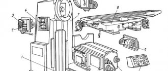
Location of controls for semi-automatic machine 5k324
Location of machine controls 5k324
List of controls for semi-automatic machine 5k324
- Milling method switch (“Down” or “Upstream”)
- Light switch
- Cooling switch
- Cycle switch
- Light - vertical feed is on
- Cutter rotation switch
- Light - radial feed is off
- Light bulb - machine “On”
- Hydraulic pump start button
- Hydraulic pump stop button
- Main drive start button
- Main drive stop button
- Cycle start button
- Cycle stop button
- Fast table approach button
- Rapid table retraction button
- Button for enabling the rapid movement of the caliper “Up”
- Button for enabling the rapid movement of the caliper “Down”
- Light - cutter movement is on
- “Start” button for moving the cutter
- Stop button for moving the cutter
- Vertical feed on/off handle
- Pressure gauge
- Table Clamp Screw
- Emergency stop
- Stop for switching off the accelerated table retraction
- Square for tensioning the main drive belt drive
- Differential clamp screw when machining spur and worm wheels
- Emergency stop
- Stop for switching off the rapid table approach
- Square for manual movement of the stop
- Handle for fixing the position of the table stop
- Square for manual table movement
- Control valve
- Line switch
- Counter support bracket fastening handle
- Stop for automatic control of machine operation according to cycle 37A - Caliper carriage clamping screw
- Focus automatic control work rate per cycle
- Ruler with vernier for turning the caliper at an angle
- Square for manually turning the caliper at an angle
- Square for manual movement of the caliper
- Square for manual rotation of the chip conveyor auger
- Auger raising and lowering square
- Table Clamp Screw
- Replacement gears for cutting prime teeth
- Emergency stop
- Square ramrod fixed mandrel cutter
- Emergency stop
- Cooling tap
- Emergency stop
Note. To avoid accidents when processing spiral wheels, it is necessary to install emergency stops 46, 48, which limit the vertical movements of the milling support carriage, according to the actually possible travel of the support. The differential clamp screw 28 should be released.
List of components of gear hobbing machine 5k324
- Gr.11 - Bed
- Gr.16 - Conveyor
- Gr.22 - Drive box
- Gr.32 — Caliper strut
- Gr.Z6 - Caliper carriage
- Gr.42 - Distribution box
- Gr.44 — Feed box
- Gr.52 - Caliper
- Gr.61 – Table
- Gr.71 - Counter support
- Gr.75 - Hydraulic drive
- Gr.76 – Control valve
- Gr.81 - Cooling
- Gr.84 – Electrical cabinet
- Gr.85 – Electric drive
- Gr.92 - Accessories
5M32 Semi-automatic vertical gear hobbing machine. Purpose and scope
The 5M32 gear hobbing machine replaced an outdated model in production and was replaced in production by a more advanced model -.
The vertical gear hobbing machine 5M32 is designed for milling cylindrical spur and helical gears, as well as worm wheels using the radial feed method in single, small and medium-scale production.
Operating principle and design features of the machine
Cutting of gears is carried out by the method of running in the cutter and the workpiece using the methods of “downstream” and “counter” gear hobbing with diagonal and normal feeds.
When gear hobbing with a diagonal feed, the cutter moves along the tooth being cut and at the same time along its own axis, which significantly increases its durability.
The design of the 5M32 machine provides the possibility of radial cutting of the cutter into the workpiece, which reduces machine processing time.
When processing spur gears in the machine, the following movements must be carried out:
- main movement
- vertical caliper feed
- table rotation and caliper installation movements
In automatic cycles, in addition, radial feed and installation movements of the table are performed. When processing helical wheels, additional rotation of the table is necessary to process the teeth located along the helical line.
When processing worm wheels using the radial feed method in the machine, the following occurs:
- main movement
- radial feed and table positioning movements
The machine operates in a semi-automatic cycle.
The machine is made in accordance with accuracy standards according to GOST 659-67.
Design of semi-automatic gear hobbing machine 5M32
Types of wheels cut on a 5M32 gear hobbing machine
On 5M32 machines you can cut:
- cylindrical spur wheels (Fig. 32, a)
- helical (Fig. 32, b)
- worm wheels using radial (Fig. 32, c) and axial feed methods
With the radial feed method, the workpiece can be fed to the cutter or vice versa. Using the rolling method, you can also mill spline shafts, polyhedra, cut teeth on chain sprockets, ratchet wheels, etc. For all types of these special gears, hob cutters of appropriate profiles are used.
Cutting cylindrical straight and helical gears, as well as worm wheels using the radial feed method - these are the main types of work for which the machine is best suited.
Methods of working on a 5M32 gear hobbing machine
Wheel cutting can be carried out either by the counter method, in which the vertical feed of the cutter occurs from top to bottom (Fig. 33, a), or by the passing method, in which the vertical feed of the cutter occurs from the bottom up (Fig. 33, b). With downstream hobbing, it is allowed to increase the cutting speed by 20-25% compared to the upstream method while simultaneously reducing the roughness of the tooth surface.
This machine can cut cylindrical wheels with a diameter of up to 800 mm (with a module of up to 10 mm and vertical movement of the cutter - 360 mm). The largest diameter of the hob cutter installed in the milling support is 180 mm with a length of 175 mm. The degree of processing accuracy corresponds to class 7 according to GOST 1643-72.
The design of the machine provides mechanisms that provide advanced methods of gear hobbing: radial cutting of the tool into the workpiece, diagonal feed, up and down milling, the possibility of using cutters of large diameter, length, etc. Increased cutter rotation speed and feed, a significant increase in the power of the main drive in combined with the high rigidity of the machine, they allow operation at elevated cutting conditions and allow the use of sharpened and carbide hobs.
The vertical location of the axis of the wheel being cut with a stationary support stand and a movable table provides the necessary rigidity and stability in operation. The massive rear rack, rigidly connected to the table, ensures reliable operation of the machine without additional attachment to the support rack by the upper crossbar. The machine operation cycle is automated. All working and auxiliary movements: quick supply of the workpiece to the tool, gear cutting, quick retraction of the wheel and tool to the starting position and stopping the machine are carried out automatically. Chip removal is carried out by a screw conveyor located inside the frame. To clamp the workpiece, the machine can be equipped with a hydromechanical device mounted in the table.
Description of the kinematic diagram of the 5K328A semi-automatic gear hobbing machine
On the machine (Fig. 132) you can use a hob cutter to cut cylindrical wheels with straight and helical teeth with longitudinal, radial and diagonal feed and worm wheels with radial, tangential and diagonal cutting. The largest diameter of the cut wheel is 1250 mm, the largest module is 12 mm.
The machine has three lead screws:
- vertical propeller
- radial screw VR
- tangential screw BO for moving the cutter along its axis
These screws can be included either alternately, or in pairs, or all together, depending on the cutting method and the shape of the teeth of the wheel being cut. The entire machine structure is usually not used. It is almost completely used only in the case of cutting a cylindrical wheel with a helical tooth with a diagonal feed.
In this case, as mentioned above, to the two shaping movements Фv(В1В2) and Фs1(П3В4) the third movement Фs2(П5В6) is added, where П5 is the axial movement of the cutter to allow the gradual introduction of all its cutting edges into work during cutting workpieces, which increases the durability of the cutter.
The first kinematic group - the cutting speed movement group Фv(В1В2) consists of an internal connection in the form of a kinematic chain connecting the cutter spindle to the table through the central bevel wheels of the differential and the guitar ix, and an external connection through which the movement from the motor D1 is transmitted to the internal circuit. The movement of the cutting speed Фv(В1В2) is adjusted according to two parameters: for the trajectory - with guitar ix and for speed - with guitar iv.
The second kinematic group - the longitudinal feed movement group Фs1(П3В4) consists of an internal kinematic connection in the form of a kinematic chain connecting the vertical lead screw of the explosive with the table through the differential and the guitar. The external connection of this group transmits movement from the D1 engine to the internal circuit and is connected to the latter through a z40 bevel wheel, which meshes with two z36 bevel wheels. The movement Фs1 is adjusted according to all five parameters: to the trajectory (helix pitch) - with guitar iy, to the path and to the initial position - with movable stops on the support (not shown in the diagram), for speed - with the feed guitar is1 and for direction - by reverse P1, located on the output shaft of the guitar feed.
The third kinematic group creates a complex tangential feed motion Фs2(П5В6), which is also used to form the tooth profile of the cut wheel. Consequently, the tooth profile is created by two movements: Фv(В1В2) and Фs2(П5В6).
Classification by drive type
Gear hobbing machines have a rather complex design. The drive type determines how the disk division can be calculated. Let's consider the features and parameters of the following common drive circuits:
A group of gear hobbing machines with a dividing worm gear table. The equipment has variable coil thickness
The gap can be adjusted in the range of 0.03-0.05 mm with a significant displacement of the worm. When considering the description, attention should be paid to the location of the systems. The features of this scheme are the installation of a separate housing for the dividing gear
In this case, the crowns are divided by adjusting the gap. The worm moves with the worm in a radial direction relative to the wheel. It is also possible to run in a workpiece by gear hobbing when installing two worm gears with different directions of turns. This adjustment method is universal and is represented by an axial displacement of one of the worms. The center can shift a certain distance depending on the features of the model. There are models on which a gear unit is installed. The gear wheel is driven by a hydraulic pump. The cylindrical type of gear can be mounted on a cutter spindle, which is represented by two halves. The gap is set by moving the wheel halves relative to each other. Considering the drawing of various machines, we note a design option when both gears of the spindle cutter have a small taper of the teeth. In this case, gear-processing equipment can be controlled by moving one wheel in the axial direction. The cutter spindle can accommodate a gear with a very large number of teeth. When carrying out the calculation, we note that the adjustment is carried out by slowing down the rotation relative to the main wheel.
In addition, other options for transmitting rotation have appeared. Some are suitable for single-unit production.
Machining on a hobbing machine with a hob cutter
Arrangement of components of gear planing machine 5A250P
Location of the main components of the gear planing machine 5a250p
- 1. Cooling switch;
- 2. Control panel on the front side of the machine;
- 3. Hydraulics activation button;
- 4. Processing mode switch - one and two passes;
- 5. Control panel on the back of the machine;
- 12. Limb, coupling and handle for rotating the spindle of the product;
- 15. Handle for moving the table;
- 16. Button for periodic lubrication of calipers;
- 17. Cycle counter;
- 20. Handle for moving calipers manually;
- 30. Main movement reverse handle (for cutting towards or away from the center)
- 33. Manual drive activation handle.
Landing and connecting bases for semi-automatic device 5k324
Landing and connecting bases for semi-automatic device 5k324
Landing and connecting bases for semi-automatic device 5k324
Types of machines
There are many gear hobbing machines that differ from each other in minor ways. In our article, models 5K32 and 5K32A will be used as an example. From the name you can understand that these models have great similarities.
5K32
Application area
- Milling of cylindrical and gear wheels.
- Processing of worm products using a movable radial screw.
- Used in small and medium-sized enterprises. Suitable for both home workshops and small and medium-sized workshops.
Processing method
The processing is based on the rolling method. It is used to cut gear-shaped wheels. Various gear hobbing methods are used - up and down. Feeding is also carried out in different ways: standard methods and diagonally.
Application area
- Milling of cylindrical and gear wheels.
- Processing of worm products using a movable radial screw.
The main difference from its relative 5K32 is its narrow focus. If the first model is excellent for small workshops and medium-sized industries, then the 5K32A is used at medium and especially large industrial enterprises.
Processing method
To cut gear-shaped wheels, the workpiece and cutter are rolled in and the finished wheel is produced. Several types of gear hobbing operations are used: the counter method of processing and the associated method. Feeding is carried out in two ways: normal and diagonally.
When feeding diagonally, processing takes place in a special way. The cutter moves not only along its own axis, but along the length of the tooth being processed. Because of this, the durability of the cutter increases.
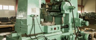
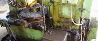
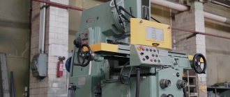
General view and general structure of the 5K328a machine
Photo of gear hobbing machine 5k328a
Photo of gear hobbing machine 5k328a
Photo of gear hobbing machine 5k328a
Processing methods
The production of worm products is carried out by other methods. For processing, 2 types of plunge are used - radial and tangential.
Radial processing method - carried out using a radial moving screw. During operation, one movement is performed (FU - B1B2), which divides and forms the surface of the teeth.
For radial processing, one plunge movement is used (BP - P7).
The tangential processing method is used much less frequently than the radial method, but no worse.
The main working mechanisms are a tangential screw and a modular hob cutter with a fence-shaped cone.
To form teeth and dividing operations, the same movement is used as in the first method (FU - B1B2). But the side surfaces of the teeth are formed 2 times, the first has already been discussed, and the second occurs simultaneously with the cutting of the cutter into the workpiece.
For tangential cutting of the cutter, namely the conical part, the movement ФS2 – П5B6 is carried out.
Technical characteristics of gear hobbing machine 5310
| Parameter name | 5K310 | 5310 |
| Basic machine parameters | ||
| Largest module of the cut wheel for steel, mm | 4 | 3 |
| The largest module of the cut wheel for cast iron, mm | 4 | 4 |
| The largest diameter of cut spur gears (0°) with a rear stand (with counter support), mm | 200 | 60..200 |
| The largest diameter of cut cylindrical helical wheels (30°), mm | 180 | |
| The largest diameter of cut cylindrical helical wheels (45°), mm | 170 | |
| Maximum angle of inclination of the cut teeth of the processed wheels, degrees | ±60 | ±60 |
| The largest diameter of worm cut wheels, mm | 60..180 | |
| Maximum length of the crown of cut cylindrical spur wheels (0°), mm | 180 | |
| The largest width of the group of cut cylindrical spur wheels (0°), mm | 180 | |
| Maximum length of the crown of cut cylindrical helical wheels (30°), mm | 150 | |
| Maximum length of the crown of cut cylindrical helical wheels (60°), mm | 20 | |
| Minimum number of teeth cut | ||
| Distance from the spindle axis to the support guides, mm | 150 | |
| Table | ||
| Table diameter, mm | 200 | 150 |
| Maximum hand/mechanical movement, mm | 130/ 130 | |
| Morse cone | KM4 | |
| Distance between the axes of the table and the cutter, mm | 45..180 | 30..160 |
| Distance from the table plane to the cutter axis, mm | 145..365 | 80..325 |
| Accelerated table movement, mm/min | 130 | |
| Manual table movement by one dial division, mm | 0,1 | |
| Moving the table stop stop by one division of the dial, mm | 0,02 | |
| Overload protection | There is | There is |
| Blocking | There is | There is |
| Locking stops | There is | There is |
| Caliper | ||
| Maximum movement of the milling support, mm | 220 | 245 |
| Accelerated movement of the caliper, mm/min | 280 | 300 |
| The largest diameter of the cutting tool (hob cutter), mm | 125 | 80 |
| Maximum length of cutting tool (hob cutter), mm | 125 | 80 |
| Diameters of milling mandrels, mm | 25 x 210 | |
| Maximum caliper rotation angle, degrees | ±60° | ±60° |
| Rotate the caliper by one division of the ruler scale, degrees | 1° | 1° |
| Rotate the caliper by one division of the vernier scale, min | 10` | 6` |
| Spindle Taper Bore | Morse 4 | Morse 3 |
| Maximum axial movement of the cutter, mm | 50 | 100 |
| The largest amount of vertical movement of the caliper at an angle of inclination of 0°, mm | 220 | |
| The largest amount of vertical movement of the caliper at an angle of inclination of 30°, mm | 170 | |
| Maximum vertical movement of the caliper at an inclination angle of 45°, mm | 150 | |
| Maximum vertical movement of the caliper at an inclination angle of 60°, mm | 30..105 | |
| Accelerated spindle movement along the axis, mm/min | No | No |
| Tool for quickly installing the caliper at an angle | No | No |
| Automatic activation of caliper reverse | No | No |
| Automatic shutdown of the machine upon completion of processing of the product | There is | There is |
| Overload protection | There is | There is |
| Machine mechanics | ||
| Cutter speed limits, rpm | 63..400 | 63..318 |
| Number of cutter speed steps | 9 | 8 |
| Limits of longitudinal (vertical) cutter feeds per table revolution, mm/rev | 0,63..4 | 0,25..4 |
| Limits of table radial feeds per table revolution, mm/rev | 0,315..2 | 0,1..1 |
| Limits of tangential feeds, mm/rev | ||
| Number of stages of longitudinal (vertical) feeds | 9 | |
| Number of radial feed stages | 9 | |
| Drive and electrical equipment of the machine | ||
| Number of electric motors on the machine | 5 | 3 |
| Main drive electric motor, kW | 4 | 1,7 |
| Rapid speed electric motor, kW | 2 | 1 |
| Stepper motion drive electric motor, kW | 0,27 | |
| Hydraulic pump drive electric motor, kW | 1,1 | |
| Cooling pump electric motor, kW | 0,12 | 0,12 |
| Total power of electric motors, kW | 7,49 | |
| Overall dimensions and weight of the machine | ||
| Overall dimensions of the machine (length x width x height), mm | 2000 x 1300 x 2040 | 1562 x 923 x 1700 |
| Weight of the machine with electrical equipment and cooling, kg | 4350 | 1550 |
List of literature on tooth processing
Acherkan N.S. Metal-cutting machines, Volume 1, 1965.
Galperin E.I. Setting up gear cutting machines, 1960.
Kozlov D.N. Gear cutting work, 1971.
Kucher A.M., Kivatitsky M.M., Pokrovsky A.A., Metal-cutting machines (Album of general types, kinematic diagrams and components), 1972.
Loskutov V.V., Nichkov A.G. Gear processing machines, 1978.
Malakhov Y.A. Gear-processing and thread-milling machines and their adjustment, 1972.
Milshtein M.Z. Cutting gears, 1972.
Ovumyan G.G., Adam A.I. Gearcutter's Handbook, 1983.
Ptitsin G.A., Kokichev V.N. Gear cutting machines, 1957.
Shavlyuga N.I. Calculation and examples of adjustments for gear hobbing and gear shaping machines, 1978.
Guiding material for designers designing technological equipment. Basic data and seats of metal-cutting machines. NIIMASH, 1968.
Related Links. Additional Information
Home About the company News Articles Price list Contacts Reference information Download passport Interesting video KPO woodworking machines Manufacturers
Cutting gears by gear shaping
When cutting block wheels and wheels with shoulders, internal teeth, gear sectors, gear shaping is the only possible processing method. In all other cases, the choice of processing method is confirmed by a technical and economic calculation.
The lower cost of a shaper compared to a milling cutter also characterizes gear shaping positively. With increasing requirements for the degree of accuracy and a decrease in the surface roughness parameter of the teeth of the wheels being processed, the time required for gear hobbing grows faster than the time for gear shaping.
When cutting gears without radial feed, a special cutter is used, the number of teeth of which is twice as large as that of the wheel being cut (Fig. 3, a).
The cutter has a recess for removing the finished part from the machine and installing the workpiece. One half of the cutter is intended for roughing of teeth, the second for finishing. The thickness of the rough teeth is less than the thickness of the finishing teeth by the amount of double the allowance for finishing chiselling. The wheel is cut in two revolutions. During the first revolution, the roughing teeth of the cutter cut the depressions, leaving an allowance on their sides, which is cut off by the finishing teeth of the cutter during the second revolution of the workpiece.
A cutter with two notches and a number of teeth four times greater than the number of teeth of the wheel being cut ensures the processing of the teeth of one workpiece in half a turn of the cutter (Fig. 3, b).
Simultaneous processing of several workpieces with one combined cutter increases the productivity of the process (Fig. 3, c). The workpieces are installed in machine spindles, which rotate around their axis and, together with the table, about the axis.
Rice. 3. Kinematic schemes of chiselling using the rolling method : a - with a special chisel with one notch; b - a special cutter with two notches; c - with a special combined cutter (Z1 - zone without teeth; Z2 - lead-in zone; Z3 - zone of rough teeth; Z4 - zone of finishing teeth); g - two wheels with one hammer; d — dowel-firmware; e - complete cutters; g - two crowns with two cutters; 3 - two crowns with a cutter and a hob cutter
The characteristics of domestic gear shaping machines are given in Table. 4.
Table 4. Technical characteristics of gear shaping machines
| Machine model | Largest dimensions of cut wheels, mm | Number of double ram strokes per minute | Main drive power, kW | Duger diameter, mm | Circular feed, mm/in. move | Group of machines | |
| diameter | module | ||||||
| 5V12 | 200 | 4,0 | 200…600 | 2,2 | 80,0 | 0,1…0,46 | I |
| 5121 | 200 | 4,5 | 125…700 | 2,3/2,9 | 80 | 0,1…0,5 | |
| 5122 | 200 | 5,0 | 200…850 | 2,1/3,0 | 100 | 0,16…0,6 | |
| 5M14 | 500 | 6,0 | 125…400 | 2,8 | 100 | 0,17…0,51 | II |
| 5140 | 500 | 8,0 | 65…450 | 3,0 | 125 | 0,14…0,75 | |
| 5A140 | 500 | 8,0 | 55…560 | 5,0/6,3/10 | 125 | 0,01…1,0 | |
| 5V150 | 800 | 12 | 33…188 | 4,8/5,7/7,5 | 200 | 0,2…1,5 | III |
| 5V150P | 800 | 12 | 33…188 | 4,8/5,7/7,5 | 200 | 0,2…1,5 | |
| 5M150 | 800 | 12 | 33…188 | 4,8/5,7/7,5 | 200 | 0,2…1,5 | |
| 5M150P | 800 | 12 | 33…188 | 4,8/5,7/7,5 | 200 | 0,2…1,5 | |
| 5V161 | 1250 | 12 | 33…188 | 4,8/5,7/7,5 | 200 | 0,2…1,5 | |
| 5V161P | 1250 | 12 | 33…188 | 4,8/5,7/7,5 | 200 | 0,2…1,5 | |
Technical characteristics of gear planing machine 5A250P
Technical characteristics of gear planing machine 5a250p
Machine for cutting spiral bevel wheels model 528c. Manual for the machine, ENIMS, MZKRS 1956.
Instructions for calculating the adjustment settings of gear cutting machines models 525 and 528 for cutting bevel wheels with spiral teeth, ENIMS, MZKRS.
Guidelines for calculating the geometric dimensions of hypoid gears and settings for cutting them on machines models 528s, 528s, 5a27s1, Saratov Heavy Gear Cutting Machine Plant, 1967.
Manual for calculating the settings of machines 528s, 525 and 5a27s4p for cutting bevel wheels using the rolling-in method, Saratov plant of heavy gear cutting machines, 1969.
List of literature on tooth processing
Acherkan N.S. Metal-cutting machines, Volume 1, 1965.
Galperin E.I. Setting up gear cutting machines, 1960.
Kozlov D.N. Gear cutting work, 1971.
Kucher A.M., Kivatitsky M.M., Pokrovsky A.A., Metal-cutting machines (Album of general types, kinematic diagrams and components), 1972.
Loskutov V.V., Nichkov A.G. Gear processing machines, 1978.
Malakhov Y.A. Gear-processing and thread-milling machines and their adjustment, 1972.
Milshtein M.Z. Cutting gears, 1972.
Ovumyan G.G., Adam A.I. Gearcutter's Handbook, 1983.
Ptitsin G.A., Kokichev V.N. Gear cutting machines, 1957.
Shavlyuga N.I. Calculation and examples of adjustments for gear hobbing and gear shaping machines, 1978.
Guiding material for designers designing technological equipment. Basic data and seats of metal-cutting machines. NIIMASH, 1968.
Related Links. Additional Information
Home About the company News Articles Price list Contacts Reference information Download passport Interesting video KPO woodworking machines Manufacturers