Information about the manufacturer of the semi-automatic vertical gear hobbing machine 5K32
Manufacturer of the vertical gear hobbing semi-automatic machine 5K32 Yegoryevsky Machine Tool Plant Komsomolets , founded in 1930.
During its existence, the plant has produced over 60 models: gear hobbing, gear shaping, gear grinding, gear rounding and other gear processing machines.
Products of the Yegoryevsk Machine Tool Plant Komsomolets, SZK
- 5A12
- semi-automatic vertical gear shaping machine Ø 208 - 5A140P
- semi-automatic vertical gear shaping machine Ø 500 - 5B150
– semi-automatic vertical gear shaping machine Ø 800 - 5B833
- vertical gear grinding machine for cylindrical gears Ø 200 - 5D32
- vertical gear hobbing machine for cylindrical gears Ø 800 - 5E32
- vertical gear hobbing machine for cylindrical gears Ø 800 - 5K32
- vertical gear hobbing machine for cylindrical gears Ø 800 - 5K32A, 5K324A
- vertical gear hobbing machine for cylindrical gears Ø 800 - 5K324
- vertical gear hobbing machine for cylindrical gears Ø 500 - 5K328A
- vertical gear hobbing machine for cylindrical gears Ø 1250 - 53A11
- vertical gear hobbing machine for cylindrical gears Ø 1250 - 53A50
- vertical gear hobbing machine for cylindrical gears Ø 500 - 53A80
- vertical gear hobbing machine for cylindrical gears Ø 800 - 514
— semi-automatic vertical gear shaping machine Ø 500 - 532
— vertical gear hobbing machine for cylindrical gears Ø 750 - 5310
— vertical gear hobbing machine for cylindrical gears Ø 200
History of the Yegoryevsky Machine Tool Plant (ESZK)
The Yegoryevsk machine tool industry began in the workshops of the Mechanical and Electrical Engineering School at the beginning of the 20th century. Equipment was purchased for the school, on which students not only practiced, but also disassembled them, made sketches, and made parts based on them. The first machine that Yegoryevites created independently within the walls of the school was a lathe. And soon other models appeared. Since 1912, they began to make the simplest metal-cutting machines for repair services.
During the First World War, the school's workshops were busy with special orders for the army and front. They manufactured parts of Gnome aeromotors for the military air fleet, machines for the first turning of gun barrels, as well as special machines for turning projectiles.
In 1924-1926, serial production of Muntkel-type machines began in the workshops of the Komsomolets technical school. Designers work throughout the year, creating, in fact, a completely new machine from a prototype. After the approval of the commission, it is allowed to be mass-produced; initially, three such machines are made in workshops.
By 1930, a new building was built to house the plant management and assembly shop, and in 1932 construction of the main production building began. The plant-technical school is gradually expanding, the number of workers is increasing, and a design bureau is being created. The technical school is being reorganized, it is being transferred to the jurisdiction of the machine tool industry, and is being transformed into a training and production plant - a technical school plant. The number of machines produced, cross-planing and turning-screw-cutting, already reaches 257 per year.
In 1933, the technical school plant began producing the first model of a gear hobbing machine, and in 1934, the production of two more models. This becomes the beginning of a new, and subsequently the main specialization of the plant as an enterprise for the production of gear-processing machines.
November 26, 1934 becomes an important date in the history of the plant. On this day, order No. 270 of the Main Directorate of the Machine Tool Industry of the USSR was signed, according to which the educational part is allocated to an independent administrative unit - the Komsomolets Technical School, and the production part - to the State Union Yegoryevsky Machine Tool Building. By that time, almost 1,300 people were working here, the production of machine tools was 300-400 units per year.
By 1935, a foundry, a new building for mechanical assembly and tool shops were put into operation, and a garage and several residential buildings for factory workers were built. In 1940, vocational school No. 31 was organized, where qualified workers were trained for the plant.
In 1936-1940, 40 models of machine tools were mastered in a short time. The number of units produced in 1940 exceeded 700, and the number of workers at the plant was about 1,900 people. The main consumers of Komsomolets products are factories producing cars, tractors, agricultural machinery, machine tool manufacturing, mechanical and instrument making enterprises.
During the Great Patriotic War, the plant was evacuated to the Kazakh town of Toguzak; after returning, the company continued work on creating new gear-processing machines.
Egoryevsky Machine Tool Plant specializes in the production of a wide range of medium-sized gear-processing equipment with a processing diameter of up to 1250 mm and a module of up to 16 mm for various technological purposes, normal, increased, high and especially high degrees of accuracy.
The plant's program includes gear hobbing machines that operate with worm and disc cutters, including CNC machines, gear shaping machines that operate with disc cutters and cutting heads, gear grinding machines that operate with abrasive wheels, gear rounding, gear chamfering, spline milling machines that operate using the hobbing method, and a number of other machines.
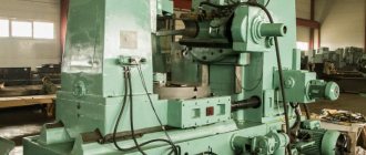
5K32 Vertical semi-automatic gear hobbing machine. Purpose and scope
The gear hobbing machine 5K32 5M32 in production
and
5E32
and was replaced in production by a more advanced model -
53A80
.
The vertical gear hobbing machine 5K32 is designed for milling cylindrical spur and helical gears, as well as worm wheels using the radial feed method in conditions of single, small and medium-scale production.
Operating principle and design features of the 5K32 machine
Cutting of gears is carried out by the method of running in the cutter and the workpiece using the methods of “downstream” and “counter” gear hobbing with diagonal and normal feeds.
When gear hobbing with a diagonal feed, the cutter moves along the tooth being cut and at the same time along its own axis, which significantly increases its durability.
5K32 machine provides the possibility of radial cutting of the cutter into the workpiece, which reduces machine processing time.
When processing spur gears in the machine, the following movements must be carried out:
- main movement
- vertical caliper feed
- table rotation and caliper installation movements
In automatic cycles, in addition, radial feed and installation movements of the table are performed. When processing helical wheels, additional rotation of the table is necessary to process the teeth located along the helical line.
When processing worm wheels using the radial feed method in the machine, the following occurs:
- main movement
- radial feed and table positioning movements
5K32 machine operates in a semi-automatic cycle.
5K32 machine is made in accordance with accuracy standards according to GOST 659-67.
Design of semi-automatic gear hobbing machine 5K32
Types of wheels cut on a 5K32 gear hobbing machine. Rice. 32.
On 5K32 machines you can cut:
- cylindrical spur wheels (Fig. 32, a)
- helical (Fig. 32, b)
- worm wheels using radial (Fig. 32, c) and axial feed methods
With the radial feed method, the workpiece can be fed to the cutter or vice versa. Using the rolling method, you can also mill spline shafts, polyhedra, cut teeth on chain sprockets, ratchet wheels, etc. For all types of these special gears, hob cutters of appropriate profiles are used.
Cutting cylindrical straight and helical gears, as well as worm wheels using the radial feed method - these are the main types of work for which the machine is best suited.
Methods of working on a 5K32 gear hobbing machine. Rice. 33.
Wheel cutting can be carried out either by the counter method, in which the vertical feed of the cutter occurs from top to bottom (Fig. 33, a), or by the passing method, in which the vertical feed of the cutter occurs from the bottom up (Fig. 33, b). With downstream hobbing, it is allowed to increase the cutting speed by 20-25% compared to the upstream method while simultaneously reducing the roughness of the tooth surface.
This machine can cut cylindrical wheels with a diameter of up to 800 mm (with a module of up to 10 mm and vertical movement of the cutter - 360 mm). The largest diameter of the hob cutter installed in the milling support is 180 mm with a length of 175 mm. The degree of processing accuracy corresponds to class 7 according to GOST 1643-72.
The design of the machine provides mechanisms that provide advanced methods of gear hobbing: radial cutting of the tool into the workpiece, diagonal feed, up and down milling, the possibility of using cutters of large diameter, length, etc. Increased cutter rotation speed and feed, a significant increase in the power of the main drive in combined with the high rigidity of the machine, they allow operation at elevated cutting conditions and allow the use of sharpened and carbide hobs.
The vertical location of the axis of the wheel being cut with a stationary support stand and a movable table provides the necessary rigidity and stability in operation. The massive rear rack, rigidly connected to the table, ensures reliable operation of the machine without additional attachment to the support rack by the upper crossbar. The machine operation cycle is automated. All working and auxiliary movements: quick supply of the workpiece to the tool, gear cutting, quick retraction of the wheel and tool to the starting position and stopping the machine are carried out automatically. Chip removal is carried out by a screw conveyor located inside the frame. To clamp the workpiece, the machine can be equipped with a hydromechanical device mounted in the table.
Main characteristics of the semi-automatic gear hobbing machine 5k32
Manufacturer: Egoryevsky Machine Tool Plant.
- The largest diameter of cut cylindrical spur wheels (0°), mm - 800 mm
- The largest module of the cut wheel is 10 mm
- The largest length of the crown of cut cylindrical spur wheels (0°) is 350 mm
- Cutter rotation speed - 50..310 rpm
- Spindle drive electric motor - 7.5 kW; 1460 rpm
- Machine weight - 7.2 t
K series gear hobbing machines
The universal gear hobbing machine 5K32 is the basic machine of the K series, on the basis of which universal machines of a simplified design and high-precision machines are made;
machines with multi-pass dividing pairs; specialized and special machines. K series gear hobbing machines:
- 5K324PA - cut wheel diameter - 500 mm, cut module - 8 mm
- 5K32, 5K32P, 5K32A - cut wheel diameter - 800 mm, cut module - 10 mm
- 5K328, 5K328P, 5K328A - cut wheel diameter - 1250 mm, cut module - 12 mm
These machines meet international standards in their technical characteristics and mechanisms that provide advanced gear hobbing methods. Gear hobbing machines basic modes. 5K324, 5K32, 5K328 are intended for use in single, small-scale and mass production.
In machines 5K324, 5K32, equipped with gear boxes with electromagnetic clutches, to change the rotation speed of the cutter and the feed rate, slide switches are used on the control panel, which turn on the electromagnetic clutches. This makes it possible to carry out an automatic two-pass gear hobbing cycle with automatic switching of speeds and feeds before the second working stroke, which reduces auxiliary time.
, 5K324 and 5K32 machines are manufactured with gearboxes and feeds, adjustable using interchangeable wheels. In the machine mod. 5K328, sliding blocks of gear wheels are used to change speeds and feeds.
Gear hobbing machines of the universal type 5K324A and 5K32A are simplified; Instead of continuous axial movement of the cutter, they provide automatic periodic movement at the end of each cutting cycle. The machines are designed to work in serial and mass production conditions.
High-precision gear hobbing machines 5K324P and 5K32P are designed for cutting wheels with a high degree of accuracy. High precision gear cutting is achieved by doubling the gear ratio of the table worm gear pair and more precise manufacturing of machine parts and assemblies, the accuracy of which affects the accuracy of the wheels being cut. These machines are used for finishing operations.
Introduction
The gear hobbing machine is designed to create cylindrical products. If the equipment contains a vertical and radial lead screw, the apparatus becomes suitable for creating worm wheels. For this purpose, modular hob cutters are used.
The best are universal gear hobbing machines that contain 3 lead screws.
The principle of creating cylindrical and worm products is based on rolling and copying the workpiece. The type of processing depends on the equipment of the mobile propeller.
In addition, machines differ in the location of the workpiece axis - vertical and horizontal. The machines are divided into two types, but are similar in design.
Vertical machines consist of a bed and a tool rack. They have a movable stand or a mobile table that moves in a radial direction. There is also an additional movable table that moves vertically.
Horizontal machines are designed to work with products of increased complexity. The movable stand moves horizontally. Horizontal machines for cutting small products have a special movable table that is used to support the product.
Below you will find detailed information about the operation of the machines.
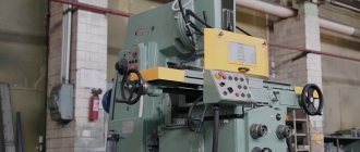
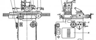
General view and general structure of the 5K32 machine
Photo of gear hobbing machine 5k32
Photo of gear hobbing machine 5k32
Photo of gear hobbing machine 5k32
Photo of a 5k32 gear hobbing machine. Back view
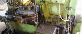
Photo of a 5k32 gear hobbing machine. Work zone
Where are they used?
Models of gear hobbing machines may differ in a fairly large number of characteristics; they are not as widespread as equipment of the turning or milling group. Therefore they are used in:
- Mechanical engineering industry.
- Aviation and automotive industries.
- Instrument making.
A universal gear hobbing machine is installed with other metalworking equipment, since processing on gear hobbing machines does not allow changing the diametrical size of the cylindrical shape. On sale you can find models suitable for use in serial, small-scale and large-scale production.
Location of machine controls for semi-automatic machine 5K32
Location of machine controls 5k32
List of controls for semi-automatic machine 5K32
- Milling method switch (“Down” or “Upstream”)
- Light switch
- Cooling switch
- Cycle switch
- Light - vertical feed is on
- Cutter rotation switch
- Light - radial feed is off
- Light bulb - machine “On”
- Hydraulic pump start button
- Hydraulic pump stop button
- Main drive start button
- Main drive stop button
- Cycle start button
- Cycle stop button
- Fast table approach button
- Rapid table retraction button
- Button for enabling the rapid movement of the caliper “Up”
- Button for enabling the rapid movement of the caliper “Down”
- Light - cutter movement is on
- “Start” button for moving the cutter
- Stop button for moving the cutter
- Vertical feed on/off handle
- Pressure gauge
- Table Clamp Screw
- Emergency stop
- Stop for switching off the accelerated table retraction
- Square for tensioning the main drive belt drive
- Differential clamp screw when machining spur and worm wheels
- Emergency stop
- Stop for switching off the rapid table approach
- Square for manual movement of the stop
- Handle for fixing the position of the table stop
- Square for manual table movement
- Control valve
- Line switch
- Counter support bracket fastening handle
- Stop for automatic control of machine operation according to cycle 37A - Caliper carriage clamping screw
- Focus automatic control work rate per cycle
- Ruler with vernier for turning the caliper at an angle
- Square for manually turning the caliper at an angle
- Square for manual movement of the caliper
- Square for manual rotation of the chip conveyor auger
- Auger raising and lowering square
- Table Clamp Screw
- Replacement gears for cutting prime teeth
- Emergency stop
- Square ramrod fixed mandrel cutter
- Emergency stop
- Cooling tap
- Emergency stop
Note. To avoid accidents when processing spiral wheels, it is necessary to install emergency stops 46, 48, which limit the vertical movements of the milling support carriage, according to the actually possible travel of the support. The differential clamp screw 28 should be released.
List of components of gear hobbing machine 5K32
- Gr.11 - Bed
- Gr.16 - Conveyor
- Gr.22 - Drive box
- Gr.32 — Caliper strut
- Gr.Z6 - Caliper carriage
- Gr.42 - Distribution box
- Gr.44 — Feed box
- Gr.52 - Caliper
- Gr.61 – Table
- Gr.71 - Counter support
- Gr.75 - Hydraulic drive
- Gr.76 – Control valve
- Gr.81 - Cooling
- Gr.84 – Electrical cabinet
- Gr.85 – Electric drive
- Gr.92 - Accessories
Main technical parameters
This type of machine has a fairly large number of technical characteristics. At the same time, setting up a gear hobbing machine allows you to change some parameters, which allows one panel to be used to produce gears with different parameters.
Gear hobbing machines have the following main technical characteristics:
- Setting up a gear hobbing machine taking into account the diameter of the crown and the maximum size of the tooth module
- An important indicator is the width of the ring gear.
- By calculating the differential pattern of a gear hobbing machine, you can set the processing mode when cutting teeth at an angle. In this case, the angle can be set within a certain range.
- Considering the universal gear hobbing machine, we note that the design has a support that moves in the vertical and transverse direction. An important point is the maximum movement rate.
- The classic device of a gear hobbing machine has a unit in which the cutting tool is fastened. Manual setting or installed CNC systems for gear hobbing machines can set the rotation speed of the cutting tool within a certain range.
- The gear hobbing machines installed have technical characteristics that determine the feed range. It can be manual or mechanical, vertical, tangential and radial.
- The operating principle is based on the transmission of rotation from the main electric motor through the drive to the cutting tool and workpiece clamping. That is why one of the main indicators is the power of the main electric motor. In addition, a horizontal or vertical gear hobbing machine may have several motors, each responsible for performing specific tasks.
- Different gear hobbing machines have different overall dimensions. It is worth considering the fact that the dimensions of the equipment determine not only the features of its installation, but also some performance qualities. So, with an increase in overall dimensions, the stroke of the support and cutting tool often increases, and the dimensions of the table also increase.
- Weight can also vary widely.
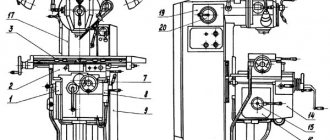
Location of components and controls of gear hobbing machine 5K32
Location of components and controls of the 5k32 machine
Let's consider the main components and controls of the vertical gear hobbing semi-automatic machine 5K32 (Fig. 34). On the horizontal guides of the frame 1, the slide 23 of the table 22 is installed. Along these guides, the slide with the table moves in the radial direction. A front stand 2 is attached to the machine bed. A support 10 with a milling head 11 is installed on vertical guides, which move in a vertical plane using a lead screw located vertically and activated by a handle 3. The support is manually moved from a handle placed on a square 4. Availability The turning circle at the support makes it possible to rotate the cutter mandrel together with the milling head in a vertical plane to a given angle and secure it in this position. The table is on ring guides and is centered by a conical protrusion. A worm wheel is attached to the table and is driven by a worm. The degree of accuracy of the gears cut on the machine depends mainly on the degree of accuracy of manufacturing this worm pair. The combination of a high-tin bronze index (worm) wheel with a grinding steel nitrided worm gives good results in maintaining the accuracy of the index pair.
To regulate the gap in the dividing pair, the worm is made with a variable coil thickness (two-step). This means that the pitch along the left profile of the worm is 19.132 mm, and the pitch along the right profile is 18.566 mm.
The table is moved in the radial direction by a lead screw, the nut of which is attached to the machine slide. To manually move the table, put a handle on square 15, and put a handle on square 16 to manually move the radial feed stop. A bracket 12 moves along the vertical guides of the rear post 13, supporting the upper end of the mandrel, which protects it from deformation caused by cutting forces. The bracket moves hydraulically by turning on handle 14. Handles 6 and 7 control the axial feed of the cutter, and stops 8 and 9 serve to turn off the movement of the caliper. Handle a on square 16 is a handle for manually moving the stop for turning on the radial feed. A bracket 12 moves along the vertical guides of the rear post 13, supporting the upper end of the mandrel, which protects it from deformation caused by cutting forces. The bracket moves hydraulically by turning on handle 14. Handles 6 and 7 control the axial feed of the cutter, and stops 8 and 9 serve to turn off the movement of the caliper.
Handle 17 serves to fix the installation of stops. The stops are used for emergency fast approach of table 18, shutdown of quick approach of table 19, stop of quick withdrawal table 20 and emergency 21. When the emergency stop is activated, the entire electrical circuit of the machine is provided and only manual movements are possible. On the control panel 5 there are buttons to turn the hydraulic pump on and off, start and. stopping the main electric motor, rapid approach - table retraction, support, as well as switches for the milling method (downwind or upwind), lighting, cycle.
Setting up a machine for cutting cylindrical spur wheels. When cutting cylindrical spur wheels, the milling cutter is given a rotational movement in the direction of arrow A (see Fig. 32). If the cutter is left-handed, then the wheel being processed should rotate in the direction indicated by arrow B; if the cutter is right-handed, then in the direction opposite to the arrow.
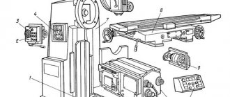
Design and operating characteristics of the main components of the 5K32A semiautomatic device
Bed 2 (Fig. 66) is the base of the machine. The support stand 9 is fixedly fixed on it and there are horizontal prismatic guides that serve to move the table 18 in the radial direction.
The table 18 consists of a body and a rotating part. The table body moves along the guides of the frame 2 and serves to feed workpieces in the radial direction. The rotating part 16 is designed to install workpieces and impart rotational motion to them. Cam 22, acting on switch 23, disables table movement to the left if switch 24 does not operate. Similarly, cam 29 acts on switch 27, disabling table movement to the right if switch 26 does not operate.
The counter support 14 consists of a housing, a slide and a folding bracket. The body is rigidly connected to the body of the table 18. The slide 13, using a hydraulic cylinder, raises and lowers the folding bracket 12, which with the center (or a steady-rest bushing) supports the upper end of the mandrel and the workpieces installed on it
Support 11 is designed to install the cutter and rotate its axis at the desired angle φ to the workpiece being processed.
The carriage 10 serves to move the support 11 in the vertical direction.
The support stand 9 has guides for moving the carriage 10. The control panel 4, the motion distribution box 3, the feed box 19 and the electrical cabinet 15 are located on the stand.
Hydraulic drive 1 consists of a vane pump, a pressure spool, a pressure switch, a pressure gauge, two cylinders and a hydraulic motor.
One of the cylinders, controlled by crane 17, is used to raise and lower the slide 13 and the folding bracket 12. The second cylinder, located in the rack 9, is intended for additional loading of the milling support in order to eliminate gaps in the screw pair that performs the vertical feed of the carriage 10. This is necessary for increasing the accuracy of carriage movement, which is especially important during “climbing” milling.
The machine operates in an automatic cycle . The machine can use either the “climbing” or “counter” gear hobbing method.
"Downstream" method of gear hobbing . When the electric motor M2 and coupling Mf1 are turned on (Fig. 67, a), the table and workpiece are rapidly brought to the cutter. At the end of the table supply, cam 24 (Fig. 66) presses switch 25, electric motor M2 is turned off (Fig. 67, a) and at the same time electric motor M1 and clutch Mf4 are turned on. The table is fed radially (cutting the cutter into the workpiece). After cutting in, screw XXVII, having reached the stop a on the frame, stops the table, and the switch located in the feed box turns off the couplings Mf1 and Mf4. Radial feed stops. At the same time, the electromagnetic clutches Mf2, Mf4 are turned on and the caliper is fed vertically upward to process the wheel teeth with a “passing” feed.
After finishing the processing of the teeth, cam 5 (Fig. 66) presses switch 6, which turns off the electric motor M1 (Fig. 67, a) and couplings Mf2, Mf4, and the vertical feed of the caliper stops. The electromagnetic clutch Mf1 and the electric motor M2 are turned on; the table is rapidly moved to the right to a position at which cam 28 (Fig. 66) presses switch 26. Switch 26 disables clutch Mf1 (Fig. 67, a) and electric motor M2. The accelerated table retraction is stopped. At the same time, the Mf2 clutch and the M2 engine are turned on. An accelerated downward movement of the caliper takes place, during which cam 8 (Fig. 66) presses switch 7. The switch turns off the electric motor M2 (Fig. 67, a) and clutch Mf2. In one case, this ends the processing cycle.
In another case, when the caliper is in the lower position (Fig. 66), under the action of cam 8, switch 7 turns on the time relay and the MZ electric motor (Fig. 67, a). The cutter moves at a speed of 12 mm/min. The amount of movement is set using a time relay, adjusting it in the range from 0.4 to 180 s. At the end of the cutter movement, the relay turns off the MZ electric motor. The cycle of movements ends.
"Counter" gear hobbing method . With this method, switching movements in the machine is similar to the “climbing” milling method, only the vertical feed of the support is performed from top to bottom, and the accelerated movement is from bottom to top. The purpose of the cams and switches changes accordingly.
Radial plunge . With this method of work, accelerated approach of the table, radial feed and its shutdown under the action of screw XXVII (Fig. 67, a) are carried out in the same way as with “climbing” milling, with the only difference being that after turning off the radial feed, the vertical feed does not turn off , and the cutter continues to mill teeth around the entire circumference of the worm wheel.
After milling is completed, the M1 electric motor and all movements in the machine are turned off.
Vertical feed . In a milling cycle with only one vertical feed, the electric motor M1 and clutch Mf2 are turned on. At the same time, during “downstream” milling, the Mf4 clutch is engaged and the caliper moves upward. During “counter” milling, instead of the Mf4 clutch, the Mf3 clutch is engaged and the caliper moves downwards.
At the end of milling, cam 5 (Fig. 66), pressing switch 6 (or cam 8 on switch 7), turns off the electric motor M1 (Fig. 67, a) and couplings Mf2, Mf4 (or Mf3). The caliper feed is switched off.
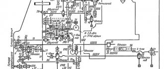
Kinematic diagram of gear hobbing machine 5K32
Kinematic diagram of gear hobbing machine 5k32
Movements in the machine . The main movement is the rotation of the cutter. Feeds: vertical - calipers 3, radial - table 5. Dividing rotation of the table and workpieces. Accelerated movements: caliper, table, cutter movement, table rotation 4.
When processing spur wheels in the machine, the following movements must be carried out: main movement, vertical feed of the caliper, rotation of the table and installation movements of the caliper. In automatic cycles, in addition, radial feed and installation movements of the table are performed. When processing helical wheels, additional rotation of the table is necessary to process the teeth located along the helical line.
When processing worm wheels using the radial feed method, the machine performs: main movement, radial feed and installation movements of the table.
For cutting spur gears, the machine is equipped with the following kinematic chains:
- Main rotational movement of the cutter
- Dividing, coordinating the rotational movements of the hob cutter and the wheel being cut
- Vertical Feed Hob Cutter
Main settings
Let's take a closer look at the technical characteristics of the equipment.
As already mentioned, the equipment is intended for creating worm and cylindrical products, and is also divided into 2 types - vertical and horizontal.
The equipment has straight and helical gear teeth. The profile of a part can be formed in different ways, depending on the type of processing. The tooth shape differs only in length, determined by touch.
The structure of equipment with the copying method is simple and includes three groups:
- FV(B1).
- FS(P2).
- Division D(B3).
Equipment that is based on the rolling-in method is also divided into groups:
- FV (B1 B2) – dental profile.
- FS(P3) – spur profile.
- FS (P3 B4) – oblique profile.
When copying workpieces, the cutting parts of the tools must match the shape of the gear. After cutting the cavities, the head rotates, 1 cavity - 1 rotation of the teeth. For rotation, a division method is used, which is carried out by a special internal mechanism.
When the material is rolled in, the gears begin to move continuously. The movement is carried out by the main processing tool. The type of rolling depends on the type of movement - hot or cold.
Lubrication diagram for gear hobbing machine 5K32
Lubrication diagram for gear hobbing machine 5k32
List of equipment for the lubrication system of the 5K32 gear hobbing machine
- Lubrication and hydraulic system reservoir
- Coolant reservoir
- Plate filter G41-II
- Check valve G51-22
- Supplying oil from the hydraulic system to the lubrication system
- Oil supply to tank 15 of the rack and to the caliper
- Gears, electromagnetic clutches and bearings in the motion distribution box
- Lubrication distributor for motion distribution box
- Differential bearing and bevel gears, bevel gears with drive box bearings located in the frame
- Guitar stand mechanism lubricant bath
- Worm pair
- Lubricant supply to the distributor of the motion distribution box
- Lubricant supply to the guitar mechanism bath
- Vertical shaft bearings
- Bath rack
- Bearings in the caliper carriage
- Lubricant supply to the oil receiver of the caliper carriage
- Caliper carriage bearings
- Lubricant supply to the distributor in the caliper to lubricate the caliper mechanism
- Guide posts
- Caliper
- Tangential feed worm
- Caliper lubrication eye
- Removable bearing
- Caliper drain
- Bed guides
- Counter support guides
- Bracket axis
- Bracket bushing
- Lubrication control tube for table ring guides
- Oil filling plugs in the table
- Lubricant supply to the feed box
- Gears and bearings of the diagonal feed box
- Lubricant supply to the lubricant control eye of the caliper strut
- Table
- Table ring guide lubrication regulator
- Lubricant supply to table ring guides
- Table lubrication control window
- Table mechanisms and bed guides
- Guitar action bearings, pins and gears
- Feed box lubrication bath
- Bearings, electromagnetic clutches and gearbox gears
- Lubricant supply to the drive box bath
- Drive box lubrication bath
- Drive box bearings and gears
- Draining excess oil from table to rack
Computer numerical control
Setting up the division guitar of a gear hobbing machine is carried out to change the parameters of the cut teeth. CNC gear hobbing machines have main components that can be adjusted to the cutting conditions; they have high movement accuracy. CNC machines can be characterized as follows:
- Can be used for cutting bevel gears, as well as bevel wheels. Numerical control allows you to set the main processing modes.
- When drawing up a processing program, all parameters are calculated. However, the division of the crown is somewhat different; tuning of the guitar is not required. This is due to the fact that a vertical gear hobbing machine or a horizontal type with CNC has movable units, the position of which and the main performance indicators are adjusted by the created program.
CNC Hobbing Machines
Modern equipment does not require significant operator intervention, since the division guitar is often absent. Such gear cutting models are expensive and difficult to maintain. Therefore, in most cases, it is advisable to install and use a processing machine that has a differential guitar design.
Technical characteristics of gear hobbing machine 5K32
| Parameter name | 5K32 | 5K324 |
| Basic machine parameters | ||
| Largest module of the cut wheel, mm | 10 | 8 |
| The largest diameter of cut cylindrical spur wheels (0°), mm | 800 | 500 |
| The largest diameter of cut cylindrical helical wheels (30°), mm | 500 | 400 |
| The largest diameter of cut cylindrical helical wheels (45°), mm | 350 | 300 |
| The largest diameter of cut cylindrical helical wheels (60°), mm | 120…250 | 120…250 |
| The largest diameter of cut worm wheels, mm | 800 | 500 |
| Maximum length of the crown of cut cylindrical spur wheels (0°), mm | 350 | 300 |
| Maximum length of the crown of cut cylindrical helical wheels (30°), mm | 200 | 200 |
| Maximum length of the crown of cut cylindrical helical wheels (45°), mm | 150 | 150 |
| Maximum length of the crown of cut cylindrical helical wheels (60°), mm | 130 | 130 |
| Minimum number of teeth cut | 12 | 12 |
| Table | ||
| Table diameter, mm | 630 | 500 |
| Distance between the axes of the table and the cutter, mm | 80…500 | 60…350 |
| Distance from the table plane and the cutter axis, mm | 210…570 | 210…570 |
| Accelerated table movement, mm/min | 170 | 170 |
| Manual movement of the table per one revolution of the dial, mm | 0,5 | 0,5 |
| Caliper | ||
| Maximum movement of the caliper, mm | 360 | 360 |
| Accelerated movement of the caliper carriage, mm/min | 550 | 550 |
| The largest diameter of the cutting tool, mm | 200 | 200 |
| Minimum length of cutting tool, mm | 200 | 200 |
| Diameters of milling mandrels, mm | 32; 40 | 32; 40 |
| Accelerated spindle movement along the axis, mm/min | 130 | 130 |
| Distance from the spindle axis to the support guides, mm | 319 | 319 |
| Maximum angle of inclination of the teeth of the cut wheel, degrees | ±60 | ±60 |
| Rotate the caliper by one division of the ruler scale, degrees | 1° | 1° |
| Rotate the caliper by one division of the vernier scale, min | 1` | 1` |
| Spindle Taper Bore | Morse 5 | Morse 5 |
| Maximum axial movement of the cutter, mm | 80 | 80 |
| Machine mechanics | ||
| Cutter speed limits, rpm | 5…310 | 5…310 |
| Number of cutter speed steps | 9 | 9 |
| Limits of longitudinal feeds, mm/rev | 0,8…5,0 | 0,8…5,0 |
| Radial feed limits, mm/rev | 0,3…1,7 | 0,3…1,7 |
| Limits of tangential feeds, mm/rev | 0,17…3,7 | 0,17…3,7 |
| Number of feed stages | 7 | 7 |
| Drive and electrical equipment of the machine | ||
| Main drive electric motor, kW/rpm | 7,5/ 1460 | 7,5/ 1460 |
| Rapid speed electric motor, kW/rpm | 3/ 1430 | 3/ 1430 |
| Hydraulic pump drive electric motor, kW/rpm | 1,1/ 930 | 1,1/ 930 |
| Cooling pump electric motor, kW/rpm | 0,15/ 2840 | 0,15/ 2840 |
| Overall dimensions and weight of the machine | ||
| Overall dimensions of the machine (length x width x height), mm | 2550 1510 2000 | 2500 1440 2000 |
| Weight of the machine with electrical equipment and cooling, kg | 7200 | 6400 |
- High-precision universal gear hobbing machines 5K324, 5K32. Management,
- Acherkan N.S. Metal-cutting machines, Volume 1, 1965.
- Galperin E.I. Setting up gear cutting machines, 1960.
- Kozlov D.N. Gear cutting work, 1971.
- Kucher A.M. , Kivatitsky M.M., Pokrovsky A.A., Metal-cutting machines (Album), 1972.
- Loskutov V.V. , Nichkov A.G. Gear processing machines, 1978.
- Malakhov Y.A. Gear-processing and thread-milling machines and their adjustment, 1972.
- Milshtein M.Z. Cutting gears, 1972.
- Ovumyan G.G. , Adam A.I. Gearcutter's Handbook, 1983.
- Ptitsin G.A. , Kokichev V.N. Gear cutting machines, 1957.
- Shavlyuga N.I. Calculation and examples of adjustments for gear hobbing and gear shaping machines, 1978.
- Guiding material for designers designing technological equipment. Basic data and seats of metal-cutting machines. NIIMASH, 1968.
List of literature on tooth processing
Related Links. Additional Information
- Classification and main characteristics of gear-processing machines
- How to buy a machine for production
- Gear hobbing machines for cylindrical wheels
- Counter milling. Climb milling when cutting gears on a gear hobbing machine
- Bevel gear. Terms and Definitions
- Testing and checking metal-cutting machines for accuracy
- Manufacturers of milling machines in Russia
- Manufacturers of metal-cutting machines in Russia
- Directory of gear processing machines
Home About the company News Articles Price list Contacts Reference information Interesting video KPO woodworking machines Manufacturers
Safety precautions
Safety precautions have a number of requirements that must be met. Items are divided into several lists.
- Allow only trained people to work.
- Perform only assigned tasks.
- The worker must wear a special uniform.
- Slippery floors are equipped with a special coating.
Requirements before starting work:
- After accepting a machine from another worker, ensure that the work area is clean.
- Availability of good lighting.
- A check of the machine's functionality is required. Also make sure you have the required amount of lubricant.
Requirements during operation:
- Fasten the part correctly and as securely as possible.
- Use special tools for fixing and processing.
- Use lifting equipment to install and remove large parts.
- Do not put your hands in dangerous places when milling.