Milling is a type of mechanical processing of materials using a special cutting tool - a milling cutter. The method allows you to obtain a high level of accuracy and the degree of roughness of the processed surface. In addition, it is distinguished by significant productivity.
Surface processing is carried out by the method of up milling, when the rotation of the cutting tool is opposite to the direction of feed, and by down milling - a method in which the direction of rotation of the cutter and feed are identical. By using cutters with cutting edges made from modern super-hard materials, the grinding operation can be replaced.
Milling equipment is divided into universal and specialized. In the first case, these are general-purpose machines for performing longitudinal and continuous milling, with or without tools mounted on a console. The second contains a mechanism for cutting threads, splines, making gears and keyways, and pattern milling.
In production, there is often a need to produce several pieces, a batch, or even a series of identical parts. For this purpose, milling equipment equipped with a pantograph is used.
In the household, the functions of a milling machine are usually performed by a manual milling machine. To perform the maximum range of work, the milling cutter is equipped with a whole set of accessories. The main equipment is supplied with the equipment, additional equipment can be purchased or manufactured independently. These are a variety of stops, clamps, templates. But you can go even further and make a copier for milling volumetric parts.
Milling and copying equipment: operating principle
The operating principle of such a device is to clearly transmit the movements of the copy head through the holder profile to the cutting tool.
It is quite difficult to purchase a copy milling machine, so craftsmen make it with their own hands from scrap materials. Everything happens by trial and error. Therefore, experts advise first assembling a duplicate carver, and only then introducing it into mass production. As a rule, this stage is preceded by more than one serious adjustment and alteration.
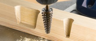
How the ring works
It works very simply: by moving the router along the template (inside, as with numbers, or outside), you can get a pattern corresponding to the template. This method can be used to make an eye-catching door sign, but is especially useful when, for example, you need to install flush hinges on multiple cabinet doors. In such a case, you can make your own template and mill the required number of grooves on it to install the hinges. It will take time to make the template, but then each loop groove will take only a few seconds. After all, to make a loop groove with a regular chisel, it will take much more time.
Ready template
We bought a ready-made template with numbers. It is very similar to the templates used to draw numbers with a pencil.
manual router, it is necessary to use the appropriate devices - copying rings for the router.
Copy rings are a round plate that has a protruding shoulder.
When the equipment is operating, the collar slides around the template.
With the help of this component, the necessary trajectory of the cutter is ensured.
The mounting location for this device is the base of the router.
A variety of different types can be used to secure it.
Most often it is screwed into the hole with a thread.
Some copying rings are equipped with special antennae that are inserted into special holes when they are attached to the cutters. Copy rings can also be screwed on. Screws are most often used for this purpose.
When choosing this device, it is imperative to pay attention to its size. In terms of its diameter, it should match the diameter of the cutter as accurately as possible.
In this case, the selection of the ring is carried out in such a way that its diameter does not come into contact with the cutting parts of the cutter. To compensate for the diameters between the ring and the cutter, templates are selected so that they are smaller than the finished parts.
Milling and copying equipment: areas of application
Milling copying machines can process not only flat, but also three-dimensional parts. With their help, along with simple milling operations, you can perform engraving, repeat drawings, patterns and inscriptions. The design of the machine is quite simple, and any craftsman can make it.
Copy-milling machines allow you to process not only wooden parts, but also cast iron, steel and plastic workpieces, as well as products made of non-ferrous metals. This is ensured by high-quality tools made of high-speed steel and hard alloys. The copying machine allows you to mill not only straight, but also curved surfaces. In this case, the details are completely identical.
Copy bushings for router
Installation should be done using two mounting bolts. They are mounted in the threaded holes on the base of the router that are available there. There is a separate class of bushings; they are height adjustable. They must be used where a tight fit of the sleeve itself to the template or rule is required over an extremely large area. They are fixed with a clamping screw or screwed in from the bottom of the plate. The manufacturer makes the diameters of the guide surface of the bushing different in size and does this in order to be able to work with cutters of different diameters, as well as create combinations of cutters with bushings. The length of the segment limited by the edge of the template and the cut line is determined by the difference in the diameters of the guide plane of the copy sleeve and the cylinder. When working with a template, you should take this parameter into account. The length of the segment from the sleeve to the cutter is approximately 3–4 mm. This is done in order to ensure the free exit of chips arising during the work process. To protect the workpiece, it is important that the flange and heads of the bushing fastening screws do not extend beyond the plane of the milling machine base. The bushing flange must be flat and fit tightly into the groove intended for it. Before installing the bushing, this groove must be cleared of chips and resin. The thickness of the template plays an important role in the work process. At the same time, it should be such a thickness that the sleeve does not rest against the workpiece. This is necessary so that the protrusion does not spoil the part. With its help, you can mill liners, recesses, and also cut out various decorative elements.
Copy ring for Fiolent router
The copy ring is a round plate with a protruding shoulder that slides around the template when working. In this way, the required trajectory of movement of the cutting element of the milling cutter is ensured. The ring is attached with screws to the base of the milling machine. During operation, the ring protects the template from the cutting effects of the cutter teeth. The copy ring is characterized by such properties as strength, reliability, durability, and wear resistance.
On the Russian market you can purchase these Fiolent products at a low price - about 10–20 USD. e. Fiolent products are budget-friendly and designed for the mass segment of consumers.
Milling and copying equipment: design
The typical design of a copy-milling machine is completely simple. It consists of a work table and a guide system with clamps for attaching the router and copier.
Making a universal copy-milling machine at home is quite difficult, and there is no great need for it. For home use, equipment with highly specialized specialization is usually created.
Application of the ring
When using a milling ring, it is possible to mill according to a template. In this case, the same pattern is copied onto the workpiece.
The production of these devices is carried out using universal technology, which ensures their excellent performance. For the manufacture of copy rings, heavy-duty metal is used, which limits the possibility of their breakage during operation.
Thanks to the presence of a special coating on the products, they are resistant to corrosion and other negative environmental influences.
Thanks to the ergonomic shape of this device, a high level of convenience is ensured during its installation on the cutter. These devices are quite small parts, which provides convenience during their storage and movement.
The copying ring is an integral part of the milling machine, with the help of which the most accurate execution is carried out. For this purpose, you just need to select the right ring.
Manufacturing of copy milling machine: materials
To create a duplicate carver at home with your own hands, you should draw a basic sketch, which will become a guide to further actions. In addition, you need to stock up on some materials. This:
- Knee cemented polished shaft Ø 16 mm.
- Linear bearings in the amount of 2 pcs.
- Rail guides 900 mm long – 2 pcs. For ease of fastening, their length is taken as a multiple of 150.
- Split linear bearings in the amount of 4 pcs. It is advisable to use bearings with a clamping screw to adjust the tightness of the fit on the guide.
- Profile pipe 30×60 with a wall thickness of up to 3 mm.
- Metal plate 900 mm long and 100 mm wide.
- End posts in the amount of 2 pcs.
- Moving element in the form of a plate – 1 pc.
- Rocker arm for attaching the copier and router – 2 pcs. The length is chosen arbitrarily.
- Movable couplings – 2 pcs.
- Profile pipe 40×40 with a wall thickness of up to 3 mm.
- Crown clutch for turning the part and template.
How to use such a device for a router?
The stencil is applied to the workpiece according to the markings and fixed. A hole is made with a drill. A cutter is inserted into it and the contour is processed.
Reference! When working with a milling cutter with cutting edges along the end, depth limiters are set on the router guides and the drill is not used.
In everyday life, groove milling using a copy sleeve is most often used when installing doors. Craftsmen cut out grooves for handles and locks on site with high precision, and make lowerings for canopy slats.
Important!
The copying sleeve allows you to make grooves of different widths with one cutter of a smaller diameter in 2 passes.
In carpentry workshops, decorative furniture elements are cut out using a template. Using shaped cutters, a carpenter produces batches of parts with complex patterns. The copying sleeve makes it accessible and simple to select grooves and recesses of any configuration. It is enough to make the template correctly and adjust the processing depth.
Making a copy-milling machine: tools
After this, you need to prepare a tool that will definitely be useful for assembling the machine structure. This:
- angle grinder;
- cutting and cleaning disc;
- welding machine;
- welding mask;
- petal disc or brush;
- self-tapping screws for fastening rail guides and moving elements;
- electric drill;
- screwdriver;
- measuring instruments: tape measure, caliper;
- center punch and scriber.
What it is?
Copy bushings for a router are special devices that can provide particularly scrupulous manipulation of parts. Copying is possible if you use a good template or, in other words, a pattern. It is worth noting that there is an alternative name - copy ring. The tool works by attaching it to the working part of the machine using screws or latches provided by the designers. Sometimes the bushing is not included in the delivery set of the router, or the standard equipment is not suitable for certain tasks.
This problem can be solved using:
purchases from a milling machine manufacturer;
purchases from template manufacturers;
ordering from private turners;
self-production of the device.
Making a copy-milling machine: step-by-step instructions
After everything is ready, the actual assembly of the copy-milling machine begins.
Step #1
It is necessary to cut two pieces 950 mm long from a 30×60 profile pipe to attach the rail guides. A margin of 50 mm is needed for installing limit switches in order to prevent linear bearings from slipping off.
Step #2
The 40×40 profile pipe needs to be cut into blanks for the base. Guided by the existing sketch, you need to cut two pieces of 1350 mm and two pieces of 900 mm.
Step #3
It is necessary to cut small racks from the same pipe. Their linear size depends on the height of the subsequently processed parts.
Step #4
Now you need to remove the rust from the pipes.
To do this, you can use a flap disc or brush. Important ! Before using the brush, pay attention to the maximum number of working revolutions on it and the grinder. The rotation speed on the brush must exceed the speed of the equipment.
Step #5
After this, we weld all the joints and clean the seams with a 6 mm thick cleaning wheel.
Step #6
Then it is necessary to ensure parallelism of the rail guides. To do this, you need to make the connection between the rack and the base of the rail guide detachable. It is necessary to take a washer according to the internal size of the rack, weld a nut to it and screw in the bolt. At this stage, the bolt is needed in order to install the nut and washer in the cavity of the stand pipe flush and in a strictly vertical position, and when welding it, do not damage the thread. This must be done with all four racks.
Step #7
Weld the posts to the base.
Step #8
At the base of the rail guide, at the junction with the racks, you need to drill holes: in the upper shelf for the bolt head, in the lower one for the thread.
Step #9
Install the rail guides on the base (30×60 pipe), pre-drilling holes, and secure with metal screws.
Step #10
Install the bases with rail guides and tighten with bolts.
Step #11
Check the parallelism of the guides. If it is missing, it is necessary to make adjustments by placing foil of different thicknesses on the racks under the guide.
Step #12
On the metal plate you need to mark and drill holes for attaching split linear bearings and end posts.
Step #13
After this, you need to make a movable element by welding 300 mm long rocker arms for the feeler gauge and router to a metal plate, then attach linear bearings to it.
Step #14
After this, the moving element must be placed on a polished shaft, along the edges of which the end posts must be installed.
Step #15
The entire structure must be installed on a metal plate 100 mm wide and the end posts must be secured with self-tapping screws.
Step #16
Then, split linear bearings must be installed on the metal plate on the bottom side.
Step #17
After this, the suspended structure is put on the rail guides with split bearings and the end switches are installed.
Step #18
Movable couplings are installed at the end of the rocker arms and a probe and a milling cutter are attached.
Step #19
In order for the workpiece and the part to rotate synchronously, it is necessary to connect them with couplings. A sprocket and crown are suitable for control. The copy milling machine is ready. The design achieved 5 degrees of freedom. Movement along the X axis is ensured by the movement of the structure along rail guides, movement along the Y axis is ensured by the movement of a moving element along a polished shaft, and movement along the Z axis is ensured by the movement of rocker arms.
Additionally, due to the movable couplings, the probe and the milling cutter can move left and right along the axis of the rocker arm, and it is possible to move the template and the workpiece simultaneously. This makes it possible to process parts of almost any shape.
What is a copy sleeve used for?
It helps to confidently guide the cutting elements of the router along a complex trajectory, maintaining the distance between the cutter blade and the edge of the template. As a rule, it is used in conjunction with various templates and rules that should be followed along the edge of the part. The outer edges of this instrument necessarily extend beyond the sole of the instrument.
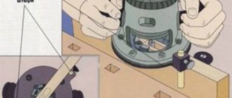
Pantograph for a router: principle of operation
The schematic diagram of a pantograph looks quite simple. It is a square divided in half. All joints are hinged, so all sides are movable, and the square easily turns into a rhombus when impacted. The zero point, located in one of the corners of the square, is fixed rigidly. Relatively, its design can be modified, turning into a rhombus. A cutting tool is installed in the middle of the square. A copier is fixed diagonally in the opposite corner of the square. The distance from the zero point to the cutter is a certain value A, and to the copier 2A. This gives a 2:1 scale. The linear size of the long and short sides of the pantograph should also differ from each other by 2 times.
Milling with copy ring
The copy ring (or bushing for a router) is a steel plate with a round hole in the center and a ring-shaped edge. It allows you to quickly create multiple copies of one part, which greatly facilitates the execution of labor-intensive small jobs, such as installing hinges for a door. In addition, the smooth base of the ring greatly facilitates the work of milling and ensures its accuracy.
One of the purposes of the copy ring is to protect the template from the action of the cutter, so its flange should be of such a size that it can easily move along the edge of the template without slowing down the movement of the cutter. To achieve the desired result, you must correctly calculate the distance between the ring and the cutter. It is calculated by the formula: subtract the diameter of the ring from the diameter of the cutter and divide by 2. If the templates contain numbers, then the calculated distance is added to them.
Calculation example for creating a template
The task is to prepare hinges measuring 30 mm by 71 mm to connect the parts of the folding table. Tools for work: cutter for grooves with a diameter of 12 mm, a copying sleeve with a diameter of 16 mm, when fastened, the ring moves relative to the base by 5 mm. A piece of board about 6 mm thick is suitable for the template. On the prepared base, mark the area where the loops are attached, from which 2 mm are counted (calculation using the formula: (16-12): 2 = 2 mm). Moreover, a correctly made template will be larger in size. In this way you can easily prepare signs with inscriptions and hinges for hanging doors.
The time spent on making the template will later pay off, since it will only take a few seconds to prepare the parts according to the template.
Pantograph for a router: materials
In order to make a pantograph with your own hands, you will need the following materials:
- Square metal profile 12×12
- Bearing 180201.
- Bushings for the outer race of the bearing.
- Pins according to the internal size of the bearing and M12 thread.
- Nut M12.
- Bolts M6×45
- Nuts M6.
- Bushing for securing the copier.
- Profile pipe 40×40
- Hinge of a metal-plastic window.
- Dye.
- Masking tape.
- Metal plate.
- Screw for fixing the copier.
What are they for?
Copy rings (bushings) are used if it is necessary to repeat a lot of homogeneous manipulations with various parts. A striking example of this is the insertion of various fittings into doors, namely:
regular and masked loops;
strips for latches.
Instead of copy bushings, cutters equipped with bearings are sometimes used. There are two particular options: with the bearing placed above the cutter or on its leading edge. The negative side of this solution is the inability to immerse the tool deeply into the material, so the ring is more effective. When using it, you can not be limited by the height of the ends of the templates.
Experts note that success can be achieved if the dimensions of the bushing and cutter are chosen correctly. Their discrepancy does not allow milling to be performed correctly. The difference between the dimensions of the rings and the cutting tool is clearly planned by designers when creating templates. Also, the optimal result is achieved if the router has no backlash under load in both the longitudinal and transverse planes.
The outer section of the rings is centered with respect to the cutting section of the cutter.
Pantograph for a router: step-by-step instructions for making it yourself
Let's proceed to the actual production of the pantograph.
Stage No. 1. Workpiece cutting
It is necessary to mark and cut the square profile according to the calculated dimensions. For convenience, you can use masking tape and a metal plate. The tape will allow for clear markings, and the plate will help make an even and high-quality cut. The blanks for the platform for the router must be cut at a right angle, and the sections of the profile for the connecting rods must be beveled for maximum fit of the bearing sleeve.
Stage No. 2. Drilling technological holes
All workpieces must be chamfered and holes Ø 6.2 mm drilled for further connection into the structure.
Stage No. 3. Welding the platform for the router
After this, you need to weld the platform for the router.
Stage No. 4. Manufacturing of connecting rods
It is necessary to make something like a jig on the board and firmly fasten all the parts to be welded. To do this, a hole is drilled in the board, and the bearing in the bushing is clamped with a bolt, the square profiles of the connecting rods are secured with clamps. First you need to insert two washers between them and fasten them with bolts. After this, all joints of the structure are scalded and cleaned. Then you need to cut the bearing sleeve between the square profiles on each connecting rod. M6 bolts, washers and bearings must be removed. It is necessary to weld a mount for the router onto the frame, and an extension for scaling onto the short connecting rod at the point opposite the zero point. The connecting rods can be painted to give an aesthetic appearance.
Stage No. 5. Making a unit for attaching a copier
Now you need to machine two bushings with an internal diameter similar to the size of the copier. Drill a hole on the side and cut a thread to install the screw that secures the copier. After this, you need to cut two pieces of 12x12 squares 20-30 mm long and weld them on the side between the bushings. The size between squares should be 12 mm.
Stage No. 6. Manufacturing of the bearing lifting mechanism
It is necessary to manufacture a bearing lifting unit. To do this, the zero point finger must be welded onto a piece of 12×12 profile and secured to a 40×40 profile pipe using a loop from a metal-plastic window. The profile pipe will serve as a place for attaching the pantograph to the table with a clamp.
Stage No. 7. Pantograph assembly
The bearings must be installed in the bushings and secured securely by tightening the square profiles of the connecting rods with M6 bolts. Using your fingers, you need to assemble the connecting rods into a single structure. Secure the pantograph to the table with a clamp and install the router. The device is ready for use.
Features of the production of devices
Before making a template, it is necessary to know exactly the diameters of the cutting tool and fixture. The template should protrude outside the specified sample contour by a size equal to the difference in the radii of the sleeve and cutter. Its thickness is allowed from 2 mm to 10 mm. You can make a stencil using simple tools.
- Draw the outline of the groove on the sheet of the future template.
- Subtract the difference in the diameters of the sleeve and cutter.
- Draw a parallel line outside the contour to be cut, retreating the calculated size.
- Cut the stencil along the outer line.
Clean off burrs and sharp edges. Now it is enough to secure the template on the surface to be treated with clamps, and you can cut out the grooves.
Important!
The contact line of the sleeve with the end of the template is equal to the thickness of the sheet with which it is made. Contact voltages are small. This allows you to make devices from soft materials: plywood, plastic, plexiglass. When producing large batches of parts, it is more practical to make a stencil from steel.
What is it and what is it for?
The copying sleeve is a ring that slides along the edge of the template. As a result, the cutter exactly follows the specified contour and does not intersect the marking lines. It is impossible to cut a workpiece smoothly by guiding the tool manually, much less make several completely identical parts.
The copy sleeve consists of a ring and a flange. The axis of symmetry of the device coincides with the axis of rotation of the spindle. The flange is made according to the size of the hole in the supporting plane of the router, and is attached to it. When pressure is applied to the housing with the motor, the working part of the tool is lowered along the guides, perpendicular to the supporting sole.
The cutter ends up below the sole and cuts into the workpiece. The copying ring rests its side surface against the end of the template, preventing the tool from going beyond its boundaries. Using a stencil, you can cut out a design of any complexity onto a part. It is enough to go along the contour with a cutter, then clean the entire area of the understatement.