Other names are telepressostat and pressostat. After some time, the K contacts open and the KU contacts close. In this case, independent adjustment of the actuator will be relevant. However, sometimes situations arise in which it is necessary to adjust the device yourself: Adjustment after partial or complete repair. Start the motor - compressor from the refrigerator without a relay
When the slider moves to the right, Rv immediately opens, but this does not affect the operation of the engine, since contactors L1, L2 receive power through the economic resistor Re1 and block contact L2.
The use of single-phase switches for three-phase loads is unacceptable, since one of the phases remains permanently connected to the winding. Automated control schemes In Fig.
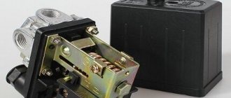
Detailed description of the pressure switch for a compressor video Connection diagram Pressure switches for compressors can be for different load connection diagrams.
In emergency situations, when the pressure level is higher than the permissible norm, and the telepressostat does not work, the safety unit comes into operation and vents the air. Thermal relay.
Check the atmospheric pressure. In accordance with the rating of the power supply line, the appropriate model of the relay unit is selected. Electric motor connection diagram FUBAG Compressor
How to connect a 380 compressor to the network
It should be understood that the engine power with such a connection, no matter how hard you try, will drop noticeably.
Thus, a delta connection uses only 70% of the engine power, and a star connection uses even less - only 50%. In this regard, it is advisable to have a more powerful engine. When connecting the motor, be extremely careful. Take your time. When changing the circuit, turn off the power supply and discharge the capacitor with an electric lamp. Work with at least two people.
So, in any connection scheme, capacitors are used. In essence, they act as the third phase. Thanks to it, the phase to which one terminal of the capacitor is connected shifts exactly as much as necessary to simulate the third phase. Moreover, to operate the engine, one capacity is used (working), and for starting, another (starting) is used in parallel with the working one. Although this is not always necessary.
For example, for a lawn mower with a blade in the form of a sharpened blade, a 1 kW unit and only working capacitors will be sufficient, without the need for containers for starting. This is due to the fact that the engine is idling when starting and it has enough energy to spin the shaft.
If you take a circular saw, a hood or another device that puts an initial load on the shaft, then you cannot do without additional banks of capacitors for starting. Someone may say: “why not connect the maximum capacity so that there is not enough?” But it's not that simple. With such a connection, the motor will overheat and may fail. Don't risk your equipment.
Whatever the capacitance of the capacitors, their operating voltage must be at least 400V, otherwise they will not work for a long time and may explode.
Possible malfunctions of the device
Several malfunctions characteristic of pressure switches are noted. In most cases, they are simply replaced with new devices. However, there are minor problems that you can fix yourself without the help of a repairman.
The most common malfunction is characterized by air leakage from the relay when the receiver is turned on. In this case, the culprit may be the start valve. It is enough to replace the gasket and the problem will be eliminated.
Frequent starting of the compressor indicates loosening and displacement of the adjusting bolts. Here you will need to double-check the threshold for turning on and off the relay and adjust them according to the instructions in the previous section.
Let's first consider how a three-phase motor is connected to a 380V network.
Three-phase motors come with either three terminals - for connection to a star only - or with six connections, with the ability to select a circuit - star or delta. The classic scheme can be seen in the figure. Here in the picture on the left there is a star connection. The photo on the right shows how it looks on a real engine frame.
It can be seen that for this it is necessary to install special jumpers on the required pins. These jumpers come with the motor. In the case where there are only 3 terminals, the star connection is already made inside the motor housing. In this case, it is simply impossible to change the winding connection diagram.
Some say that they did this to prevent workers from stealing units from home for their own needs. Be that as it may, such engine options can be successfully used for garage purposes, but their power will be noticeably lower than those connected by a triangle.
Related Posts
It must have the required pressure. However, it is not always possible to replace elements - some modifications are no longer available for sale. To eliminate this type of malfunction, you can use one of the following methods: clean the surface, which extends the service life by at least 3 months, or repair it by replacing the contacts in the terminal clamps . For a single-phase motor, a volt relay is used, with two groups of connections.
Frequent starting of the motor.
During operation, the indicators formed as a result of the elastic force of tension or compression of the springs and the pressure of the atmosphere pressed by the device are compared. The container membrane is connected to the pressure switch. The contact of this relay supplies power to the computer solenoid valve, which allows cooling water to enter the compressor compartment. The author of the article describes in detail the existing types of pneumatic relays.
Below is a diagram of connecting automation to three phases. In accordance with the rating of the power supply line, the appropriate model of the relay unit is selected.
Remember that the compressor should be depressurized no earlier than 5 minutes before soldering. Share your own experience in operating a compressor with a pressure switch, ask questions, post photos on the topic. Working and starting capacitors for teapots.
What can be redone
Low-power 380 Volt electric motors are suitable for conversion: up to 3 kW. Theoretically, powerful motors are also reconnected. But this will additionally entail the installation of a separate circuit breaker in the electrical panel and special wiring. And this work becomes meaningless if it suddenly turns out that the input cable cannot carry such a load.
Read also: Btb10 800bw how to check with a tester
Even if your network carries high loads, and you managed to convert a 3 kW motor from 380 to 220 Volts, you will be upset the first time you put it into operation. The launch will be difficult. You will decide that the work was in vain. Therefore, if you redo it, then it will be low-power models.
Connection diagram for a 3-phase motor in a 220V network connected by a star.
As you can see, the 220V voltage is distributed over two series-connected windings, where each is designed for such a voltage. Therefore, the power is lost almost twice, but such an engine can be used in many low-power devices.
The maximum power of a 380V motor in a 220V network can only be achieved using a delta connection. In addition to minimal power losses, the engine speed also remains unchanged. Here, each winding is used for its own operating voltage, hence the power. The connection diagram for such an electric motor is shown in Figure 1.
Fig. 2 shows a terminal with a 6-pin terminal for delta connection. The three resulting outputs are supplied with: phase, zero and one terminal of the capacitor. The direction of rotation of the electric motor depends on where the second terminal of the capacitor is connected - phase or zero.
In the photo: an electric motor with only working capacitors and no capacitors for starting.
Using a magnetic starter
The good thing about using a 380 electric motor connection diagram is that it can be started remotely. The advantage of a starter over a switch (or other device) is that the starter can be placed in a cabinet, and the controls can be placed in the work area; the voltage and currents are minimal, therefore, the wires are suitable for a smaller cross-section.
In addition, connection using a starter ensures safety in the event that the voltage “disappears,” since this opens the power contacts, and when the voltage appears again, the starter will not supply it to the equipment without pressing the start button.
Connection diagram for a 380V electric asynchronous motor starter:
At contacts 1,2,3 and start button 1 (open), voltage is present at the initial moment. Then it is supplied through the closed contacts of this button (when you press “Start”) to the contacts of the coil starter K2, closing it. The coil creates a magnetic field, the core is attracted, the contacts of the starter close, driving the motor.
At the same time, the NO contact closes, from which the phase is supplied to the coil through the “Stop” button. It turns out that when the “Start” button is released, the coil circuit remains closed, as do the power contacts.
By pressing “Stop”, the circuit is broken, returning the power contacts to open. The voltage disappears from the conductors and NO supplying the engine.
Video: Connecting an asynchronous motor. Determination of engine type.
If you have a three-phase electric motor, you know it doesn't come cheap. Therefore, if you need to use a single-phase motor, the thought of buying new equipment will only come to you when you do not know how to make an electric motor at home. We will tell you how to convert an electric motor from 380 to 220 Volts with your own hands.
DIY pressure switch
With known skills, as well as the presence of a working thermostat from a decommissioned refrigerator, a pressure switch can be made independently. True, it will not have any special practical capabilities, since the ability to maintain upper pressure is limited by the strength of the rubber bellows.
Thermal relays of the KTS 011 type are most convenient for conversion into a compressor pressure switch, since they have a strictly reverse sequence of operation: when the temperature in the refrigeration chamber increases, the relay turns on, and when it decreases, it turns off.
The essence and sequence of work is as follows. After opening the cover, the location of the desired group of contacts is established, for which it is enough to ring the circuit. First, the connection between the thermal relay and the compressor is finalized. To do this, the outlet pipe, together with the control pressure gauge, is connected to the unloading valve, and the contact groups are connected to the terminals of the electric motor circuit. An adjusting screw will be found under the thermostat cover. When the compressor is turned on (the receiver should be filled to no more than 10...15% of its nominal volume), the screw is rotated sequentially, monitoring the result using the pressure gauge. To set the lower position (which determines the minimum air pressure), you will have to gradually move the face button rod. To do this, the cover is installed in place, and the adjustment is actually made blindly, since there is nowhere to connect the second pressure gauge.
- Step-down transformers 380/220
For safety reasons, the pressure adjustment range using such a thermal relay cannot be more than 1...6 atm, however, using devices with a more durable bellows, you can increase the upper range to 8...10 atm, which in most cases is quite sufficient.
After checking the functionality of the relay, the capillary tube is cut off and the refrigerant contained there is released. The end of the tube is soldered into the unloading valve.
Next, work is carried out to connect a homemade pressure switch to the compressor control circuit: using a nut, the relay is attached to the control board, a thread is made on the rod, and a lock nut is screwed on, by rotating which you can adjust the limits of air pressure change.
Considering that the contact group of any thermal relay from a refrigerator is designed for fairly high currents, in this way it is possible to switch circuits of significant power, including secondary compressor motor control circuits.
How to select capacitors for a three-phase motor using it in a 220V network.
The first thing you need to know is that the capacitors must be non-polar, that is, not electrolytic. It is best to use containers of the brand ― MBGO. They were successfully used in the USSR and in our time. They perfectly withstand voltage, current surges and the damaging effects of the environment.
They also have mounting eyes that help you easily place them at any point on the device’s body. Unfortunately, getting them now is problematic, but there are many other modern capacitors that are no worse than the first ones. The main thing is that, as mentioned above, their operating voltage is not less than 400V.
Calculation of capacitors. Working capacitor capacity.
In order not to resort to long formulas and torture your brain, there is a simple way to calculate a capacitor for a 380V motor. For every 100 W (0.1 kW) 7 µF is taken. For example, if the motor is 1 kW, then we calculate it like this: 7 * 10 = 70 µF. It is extremely difficult to find such a capacity in one jar, and it is also expensive. Therefore, most often the containers are connected in parallel, gaining the required capacity.
Starting capacitor capacity.
This value is taken at the rate of 2-3 times greater than the capacity of the working capacitor. It should be taken into account that this capacity is taken in total with the working capacity, that is, for a 1 kW motor, the working capacity is equal to 70 μF, multiply it by 2 or 3, and get the required value. This is 70-140 µF of additional capacitance - starting. At the moment of switching on, it is connected to the working one and the total is 140-210 µF.
Features of the selection of capacitors.
Capacitors, both working and starting, can be selected using the method from smallest to largest. Having thus selected the average capacity, you can gradually add and monitor the operating mode of the engine so that it does not overheat and has enough power on the shaft. Also, the starting capacitor is selected by adding until it starts smoothly without delays.
In addition to the above type of capacitor - MBGO, you can use the type - MBGCh, MBGP, KGB and the like.
Remodeling stages
To convert an electric motor from 380 volts to 220, first open the motor cover to see how many ends there are on the stator windings. There can be 6 or 3 of them. If there are 6, then it is possible to change the connection diagram: if there was a “star”, you can switch to a “triangle”, and vice versa.
If there are only 3 ends, it means that inside the box the windings are already connected either by a “star” or a “triangle” (there are 6 ends in total, which are connected in pairs by terminals, there will be 3 of them, since there are 2 ends for each terminal). In this case, you will have to leave the previous scheme.
Attention! If you decide to change the connection diagram of the stator windings with three ends outside, you will have to open the motor housing with your own hands. It's labor intensive, but possible.
Winding connection
It doesn’t matter what the power source is, three-phase or single-phase, the stator windings can be connected in any of the following ways (you can read more about methods for connecting electric motors):
The windings are usually connected with a star if the motor will be powered from a 380 V network. Thanks to this, the start becomes smooth, although a third of the power is lost. The triangle is recommended when powered from 220 Volts. Inrush currents are not so high compared to those that arise from three-phase power. But the power is equal to that provided by a “star” connection if the motor is connected to 380 V.
See the diagrams below. The difference is that in the first case, all the beginnings are connected so that a three-pointed star is obtained. And in the second, the end of one winding is connected to the beginning of the next so that a figure with three vertices (a triangle) is formed.
Calculation of capacitors
When the ends of the windings are connected in a star or triangle, there are 3 places where they are joined. Terminals are placed at these places. When powered by 380 Volts, a phase is supplied to each of them. But our task, having the same 3 contacts, is to supply only 1 phase 220 Volts and zero. This can be done with your own hands, compensating for the lack of three-phase power supply with capacitors. The launcher will be active only for the duration of the launch, and the worker will be active permanently.
In order for an electric motor to start and operate well, you need to choose the right capacitor capacity. For a working drive it depends on the connection scheme. If it is a star, then the formula works:
If it is a triangle, then the formula changes its form:
Wed is the required capacity of the working storage element. U – network voltage (220 Volts). I is the current strength, which is found by the formula:
P – power, U – voltage already known to us, ƞ – efficiency, cosine “phi” – power factor. All these values can be found in the technical data sheet of your three-phase motor.
Calculating the capacitance of the starting capacitor (Cn) is simple: multiply Cp by 1.5 or 2. If Cp = 50 µF, then Cp will be from 75 to 100 µF. Alternately place one container, then another, starting the motor each time. Listen to the sound of the move: if there is no hum, then everything is in order.
Attention! Capacitors must be paper. For rebuilding an engine with your own hands, MBGP or MBGO work well. If you don’t find a drive of the required capacity, then connect several in parallel.
Assembly according to the diagram
The diagram above shows how to correctly connect the stator windings with capacitors and wires of a 220 V network with your own hands. You need to connect storage elements parallel to each other to one of the vertices of the triangle or star (provide a key to manually turn off the starting drive after overclocking). Then they are brought either to phase or to zero: it doesn’t matter. Only the direction of rotation of the shaft will depend on this.
Let's summarize.
Sometimes it becomes necessary to change the direction of rotation of the electric motor. This option is also available for 380V motors used in a single-phase network. To do this, you need to make sure that the end of the capacitor connected to a separate winding remains unbroken, and the other can be transferred from one winding, where the “zero” is connected, to the other, where the “phase” is connected.
This operation can be performed by a two-position switch, the central contact of which is connected to the output from the capacitor, and to the two outer terminals from “phase” and “zero”.
More details can be seen in the figure.
There are three-phase electric motors for 220V. Each winding of them is designed for 127V and when connected to a single-phase network in a delta circuit, the motor will simply burn out. To prevent this from happening, such a motor should be connected to a single-phase network only according to the “star” circuit.
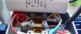
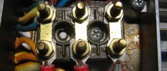
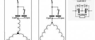
Complete set of compressor automation unit
The relay design is a small-sized block equipped with receiving pipes, a sensing element (spring) and a membrane. Mandatory subassemblies include an unloading valve and a mechanical switch.
The pressure switch sensing unit is made up of a spring mechanism, the compression force of which is changed by a screw. According to the factory standardized settings, the elasticity coefficient is set to a pressure in the pneumatic chain of 4-6 at, as reported in the instructions for the device.
The degree of rigidity and flexibility of the spring elements is subject to the temperature of the environment, therefore absolutely all models of industrial devices are designed for stable operation in an environment from -5 to +80 ºC.
The reservoir membrane is connected to the relay switch. During movement, it turns the pressure switch on and off.
The unloading element is located between the ejector check valve and the compression block. If the motor drive stops working, the unloading section is activated, through which excess pressure (up to 2 atm) is released from the piston compartment.
With further start or acceleration of the electric motor, a pressure is created that closes the valve. This prevents overloading of the drive and simplifies starting the device in switched off mode.
There is an unloading system with a time interval of activation. The mechanism remains in the open position when the engine starts for a specified period. This range is enough for the engine to achieve maximum torque.
A mechanical switch is required to start and stop the automatic system options. As a rule, it has two positions: “on.” and "off". The first mode turns on the drive and the compressor operates according to the established automatic principle. The second one prevents accidental starting of the engine, even when the pressure in the pneumatic system is low.
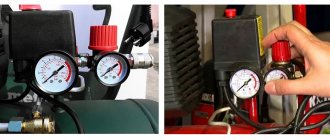
Adjustment and commissioning process
Factory set parameters do not always meet consumer requirements. In most cases, this is due to insufficient compression force at the highest point of disassembly.
The operating range of the pressure switch may also not be suitable. In this case, independent adjustment of the actuator will be relevant.
To begin setting the operating compression value, you will need to inspect the engraved plate, which indicates the parameters of the electric motor and compressor.
We only need the largest value that the device produces. This indicator indicates the maximum pressure force that can be set on the relay for the correct operation of the entire pneumatic system.
If you set the specified value (in the figure 4.2 atm), then taking into account all factors - differences in power supply, exhaustion of the service life of parts, etc. - the compressor may not reach the maximum pressure, and accordingly it will not turn off.
In this mode, the working elements of the equipment will begin to overheat, then deform and eventually melt.
Purpose
After the compressor engine starts, the pressure in the receiver begins to increase.
If the excitation rheostat slider R is moved, then a resistor will be introduced into the SHOV winding circuit. The presence of a free connector allows you to install the control pressure gauge in a place convenient for the user. Control the pressure using the pressure gauge and set the required values.
Other names are telepressostat and pressostat. To do this you will have to: Disconnect the wiring from the contacts; Cut through the motor tubes connecting it to other parts; Image 4 - biting the motor tube Unscrew the mounting bolts and remove from the casing; Disconnect the relay by unscrewing the screws; Image 5 - disconnecting the relay Next, you need to measure the resistance between the contacts; By applying the tester probes to the output contacts, normally you should get OM depending on the model of the engine and refrigerator. The working system consists of springs of different levels of rigidity that respond to changes in pressure.
There may also be other auxiliary mechanisms that require activation: a safety or unloading valve. Types of pressure switch devices There are only two variations in the design of the automatic compressor unit. With the help of a relay, it becomes possible to operate automatically while maintaining the required compression level in the receiver.
We recommend: How to fix overhead wiring
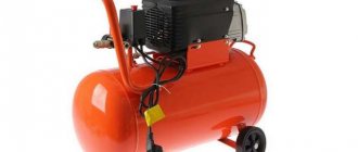
Air compressor made from auto parts
It is the largest supplier in the CIS. Scheme of automated control of an electric compressor The second contact PB1 turns on the signal relay P2 after 15 s; its closed contact can trigger an alarm, but by this time the pump mounted on the compressor manages to create the required pressure in the lubrication system, and the oil pressure switch RDM opens, interrupting alarm circuit. Control circuit for the electric drive of the fire-ballast pump When power is supplied to the circuit, even before the engine starts operating, the electromagnetic time relays RU1, RU2, RU3 acceleration relays are activated. This indicator must be less than the nominal pressure of the air blower.
Typically, the difference value is set to 1 bar. If the relay malfunctions and the compression level in the receiver rises to critical values, then in order to avoid an accident, the safety valve will operate, releasing the air.
Restarting with the KnP button is possible when contact Rв in its circuit is closed, which corresponds to the position of the Rв slider on the right. The operating system is made up of spring mechanisms with varying degrees of rigidity, reproducing the response to fluctuations in the air pressure unit.
If the pressure switch was found to be the source of the malfunction, the professional will insist on replacing the device. In addition, the pressure drop in the system will be significant. Install a control pressure gauge if it is not necessary, then the threaded inlet is also plugged. Compressor cannot gain speed REPAIR bad start FORTE VFL-50
How to change the direction of rotation
If you need to change the direction only once, then this can be done at the rework stage. To do this, it is enough to swap any two stator windings. The same goal is achieved by transferring a branch of capacitors from zero to phase, or vice versa. But if you need to frequently reverse a three-phase converted motor, a switch is needed. By assembling the electric motor according to the diagram below, you will free yourself from changing the windings every time you need to set the direction of rotation of the shaft in the opposite direction.
There is nothing difficult about converting a three-phase electric motor to a single-phase network with your own hands. The greatest difficulty will be only the calculation of the capacitance of the working capacitor and the experimental selection of the capacitance from the calculated range for the starting accumulator. But this becomes easy if you haven’t lost your technical passport and have a calculator at hand.
When operating or manufacturing this or that equipment, it often becomes necessary to connect an asynchronous three-phase motor to a regular 220 V network. This is quite realistic and not even particularly difficult, the main thing is to find a way out of the following possible situations if there is no suitable single-phase motor, and a three-phase one is lying without business, and also if there is three-phase equipment, but in the workshop there is only a single-phase network.
Read also: Brazier from a gas cylinder drawings with dimensions
DIY pressure switch
With known skills, as well as the presence of a working thermostat from a decommissioned refrigerator, a pressure switch can be made independently. True, it will not have any special practical capabilities, since the ability to maintain upper pressure is limited by the strength of the rubber bellows.
Thermal relays of the KTS 011 type are most convenient for conversion into a compressor pressure switch, since they have a strictly reverse sequence of operation: when the temperature in the refrigeration chamber increases, the relay turns on, and when it decreases, it turns off.
The essence and sequence of work is as follows. After opening the cover, the location of the desired group of contacts is established, for which it is enough to ring the circuit. First, the connection between the thermal relay and the compressor is finalized. To do this, the outlet pipe, together with the control pressure gauge, is connected to the unloading valve, and the contact groups are connected to the terminals of the electric motor circuit. An adjusting screw will be found under the thermostat cover. When the compressor is turned on (the receiver should be filled to no more than 10...15% of its nominal volume), the screw is rotated sequentially, monitoring the result using the pressure gauge. To set the lower position (which determines the minimum air pressure), you will have to gradually move the face button rod. To do this, the cover is installed in place, and the adjustment is actually made blindly, since there is nowhere to connect the second pressure gauge.
For safety reasons, the pressure adjustment range using such a thermal relay cannot be more than 1...6 atm, however, using devices with a more durable bellows, you can increase the upper range to 8...10 atm, which in most cases is quite sufficient.
After checking the functionality of the relay, the capillary tube is cut off and the refrigerant contained there is released. The end of the tube is soldered into the unloading valve.
Next, work is carried out to connect a homemade pressure switch to the compressor control circuit: using a nut, the relay is attached to the control board, a thread is made on the rod, and a lock nut is screwed on, by rotating which you can adjust the limits of air pressure change.
Considering that the contact group of any thermal relay from a refrigerator is designed for fairly high currents, in this way it is possible to switch circuits of significant power, including secondary compressor motor control circuits.
sticking out of the engine were two wires to the network and two to the button
Safety precautions
Although a drill press is easy to connect and use, working with it can be dangerous without proper safety precautions. Among them it is worth highlighting the following:
- Perform any repair or cleaning work only with the engine power off;
- use protective clothing and glasses to protect yourself from flying chips, dust, drops of cutting fluid, and parts of the drill that break;
- hide long hair under a hat, avoid working with gloves - if they get wrapped around rotating elements, they can lead to serious injuries;
- Before starting work, carefully check all moving parts of the machine for defects and damage. If they are detected, it is prohibited to use the device.
To find out more about how to connect a drilling machine, contact Metaltool and they will answer your questions in detail.
Source