A compressor is a device for compressing air masses, from which it is subsequently possible to extract the energy necessary for a huge number of different tools. Today we will look at such an important component as compressor pressure.
If the pressure is incorrectly set, even the best equipment will not function properly. In case of a breakdown or malfunction of the compressor, Megatechnika service specialists will help you.
It is important to know some rules for working with these devices.
First option
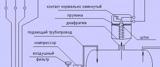
The operation scheme of all compressors is the same. After the required amount of air has been collected, the automatic control element weakens and stops air intake. An air pressure controlled relay works on the principle of pressing air onto a membrane and counteracting an elastic spring.
To manually adjust the compressor pressure, there is a switch in the form of a bolt or nuts that allows you to adjust the pressure of the unit. To access it you need to do the following:
- remove the protection in the form of a casing;
- the compressor pressure is adjusted by rotating either a bolt or two nuts, which increase or decrease the spring pressure force;
- There is a nut nearby for adjusting the differential pressure on and off;
- turn the pressure adjustment bolt to change the indicators, determine the desired indicator experimentally.
Air relay connection diagrams
The compressor pressure switch is manufactured for connection to electrical circuits of different loads. In accordance with the rating of the power supply line, the appropriate model of the relay unit is selected.
Option #1: to a network with a nominal value of 220 V
If the drive motor is a single-phase device, then a 220 V relay with two groups of contacts is installed.
Option #2: to a three-phase network with a voltage of 380 V
For a three-phase load of a 380 V circuit, one of the options can be used: a modification of the relay for 220 V or 380 V, with three contact lines, to simultaneously disconnect all three phases.
Both methods have different schemes. Let's consider the first option:
By choosing the second method, power is supplied from one phase (zero) and in this case the relay rating should be 220 V. For more details, see the following diagram:
After connecting to the power supply, you need to understand the additional capabilities provided in the air blocks for ejectors.
The second way to regulate pressure
Another method, which is sometimes much more convenient and practical than the first, is adjustment through a gearbox. A reducer is a device that takes in air already in a compressed state. This air must be transferred to the final apparatus.
These devices, gearboxes, also have a control element in the form of a valve. The pressure control range can be controlled, and the indicators depend on the power and capabilities of the compressors that are connected to the gearbox.
There are special models with the function of conveniently adjusting the supplied air pressure for each specific working tool. Sometimes such devices even have an option that relieves excess pressure, eliminating the excess and maintaining the safe, uninterrupted operation of any connected tool.
Types of pressure switch devices
There are only two variations in the design of the automatic compressor unit. The determination is made based on their operating principle. In the first version, the mechanism turns off the electric motor when the established limits of the air mass pressure level in the pneumatic network are exceeded. These devices are called normally open.
Another model with the opposite principle - turns on the engine if a drop in pressure is detected below the permissible level. Devices of this type are called normally closed.
Essential Security
Tips in the article “Why do you need a screw compressor” here.
This ability to regulate pressure is present on all units that use compressed air energy for production. Plus, the gearboxes of such machines provide pressure control at all stages in order to ensure the safe operation of all parts of the working structure.
Finished compressors are delivered to customers with factory settings. Developers optimize the operating mode of the unit to extend its life, increase productivity and simplify maintenance. Sometimes it is necessary to decide how to configure a compressor so that it meets operating conditions that differ from conventionally standard ones. Manufacturers allow some changes, describing in the instructions exactly which settings can be adjusted.
Operation and Maintenance
First of all, it should be noted that even with timely maintenance, the equipment, or some of its elements, will wear out sooner or later.
Before starting to operate the compressor, you must carefully read all factory rules and recommendations, and also regularly inspect the external structure. Any, even minor external damage can lead to premature failure of the equipment, as well as to the fact that the compressor will stop pumping pressure.
It is highly advisable to entrust all technical operations to experienced specialists who use professional tools and diagnostic equipment.
How to set the compressor to turn on automatically?
This function works on air compressors “by default”. Piston compressors have an intermittent operating mode. The engine turns on automatically and drives the injection pistons when it is necessary to pump air into the receiver. Having provided the specified pressure in the pneumatic system, the installation is turned off.
Controls the mode of the compression relay (pressostat). This device gives a control command to the engine when the pressure in the pneumatic system reaches a predetermined value. When the maximum is reached, the relay switches off the engine and the pumping stops. When the compression ratio drops to a predetermined minimum, the pressure switch turns on the electric motor to pump air into the system.
The question of setting it to turn on automatically arises if there are problems with the pressure switch. It's usually not a question of the engine turning on at all. It is often necessary to configure automatic activation at the desired compression level of the working environment.
Principle of operation
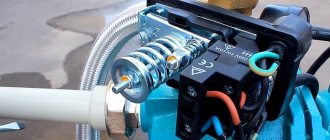
The operating principle of the automation unit is simple. The device is mounted on a pipe communicating with the receiver. The spring-diaphragm pressure switch sensor for the compressor continuously measures the pressure. As soon as it drops below the set value, the sensor rod, under the action of a spring, closes the contacts of the compressor relay and the electric motor is connected, pumping air into the tank. After reaching the set pressure, it presses the rod and opens the contacts, turning off the engine. Adjustment of these values is available to the user. In addition, when the operating pressure limit is reached, the safety valve included in the device is activated, releasing excess air from the compressor into the atmosphere.
How to set the compressor to the desired pressure?
Compressors are supplied with factory settings for switching on and off. As a rule, buyers decide to change standard settings for two reasons.
First: such changes are dictated by the technical characteristics of the connected instrument.
Second: the desire to save energy and reduce the load on the pneumatic system.
For example, a pneumatic tool is connected to the system, whose maximum pressure threshold is lower than that set on the injection unit. If you do not reduce the compression level, the tool will fail. You can use a pressure reducing valve to adjust the degree of compression of the air supplied to the pneumatic system, but this will be a half-measure. Why force the compressor unit to work with force, pumping more than necessary?
Another case: the relay is activated at a minimum compression of 8 atmospheres, and a value of 6 bar is sufficient for the connected pneumatic tool to operate. By setting the compressor to a lower pressure, you can save up to 10% in energy. The load on the pneumatic system: pipes, hoses, fittings, fittings is reduced.
To set the compressor to the desired pressure, you need to change the pressure switch settings. You should interfere with the functionality of this device only if there are no other solutions to the problem. It is better to entrust this work to a specialist.
How to set the compressor pressure switch?
This operation must be performed with the receiver full but the power turned off. You should turn on the compressor, wait until the pressure switch operates and the engine stops. The actual readings of maximum compression are recorded on the pressure gauge. Then you should cut off the electricity supply.
It is strictly forbidden to manipulate the pressure switch if the compressor is not disconnected from the power supply!
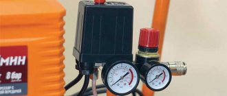
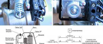
You need to remove the pressure switch cover. It is located on the receiver or supply line, usually with a red or white “compressor start” button. Black plastic box. Under the cover there are two screws (sometimes nuts). The larger screw (marked P) adjusts the maximum pressure at which the engine turns off. By rotating the screw towards the “+” or “-” signs, set the required value. If the compression ratio is set too high, the relief valve will trip.
Relay breakdowns: types and solutions
Pressure switches, like other devices, can fail. Repair in most cases is impractical; worn out, faulty working parts are immediately replaced with new ones. In any case, you must first inspect the system yourself, try to understand the cause of the malfunction, and, if possible, take action.
If malfunctions in the functioning of the system are caused by the pressure switch itself, then the only way to solve the problem is to replace the device. You can clean and change contacts, but these expensive manipulations will not give the desired results.
Air leaks from the relay when the receiver is turned on occur due to the fault of the start valve. In this case, restoration will be simple, quick and cheap - just install a new gasket instead of the worn out old one.
When the compressor is turned on frequently, you should check the adjusting bolts - they may have become loose and/or misaligned. Separately, double-check the on-off threshold of the pressure switch, make the settings according to the diagram described in the previous section.
What to do to restore the system
The list of measures depends on the type and complexity of the breakdown. The most difficult case is when the compressor does not work at all. The first thing you need to do is check the contacts for melting and make sure there is no erosion that occurs as a result of electrical sparks.
A group of contacts burns out as a result of electrical spark erosion and contact opening. If you find items on sale that can be installed instead of old ones, the repair will be relatively simple and inexpensive. But this is not always possible, since many modifications have been discontinued.
- clean problem surfaces (the effect will last for 3 months or more);
- install new contacts in the terminal clamps.
To install new terminals, bleed the air masses from the receiver, turn off the ejector power, and remove the relay. The protective housing is also dismantled, the wire that is connected to the contact group is disconnected. Using a screwdriver, remove the terminal with all the contacts, drill out the burnt and simply questionable lines. The wire is replaced with copper wire or another convenient method. It is optimal to select the wire according to the diameter of the hole. It should fit into the landing nest as tightly as possible. After inserting the element into the hole, crimping is done on both sides.
The same steps are repeated with the remaining burnt areas. When the assembly of the contact group is completed, it is installed in its old place and the pressure switch cover is screwed on.
Compressor - device and principle of operation
The name of the device in question comes from “compressio”, which is translated from Latin as “compression”. The main purpose is to compress a gaseous substance in order to move it and use pressure force .
Pressure compressors produced by modern industry are divided into several types and subtypes. Based on the method of gas compression, two large groups of devices are distinguished: volumetric and dynamic. The pressure in them is created by different methods, and accordingly the principle of operation is different.
The design of volumetric models consists of working chambers with a system of valves in which the process of compression and movement of gas is carried out. Schematically, the principle of operation looks like this: the working substance enters the chamber through the inlet valve, which opens only inward and prevents gas from escaping outward. The gas is then compressed by reducing the volume of the chamber and pushed to the outlet valve, which also opens in one direction - outward.
Dynamic designs compress gas by accelerating its movement using a screw system. As a result, the energy of motion is converted into compression force.
On a note! In addition to the principle of operation, compressor devices are divided into groups according to the type of working substance (air, steam, any gas or a mixture of them), the type of drive, the method of heat removal, the industry used, and the final pressure.
The main reasons why an air compressor does not gain pressure and how to fix it.
Depressurization of connecting elements and assemblies.
If exposed to vibration for a long period of time, seals, nuts and clamps can become loose, resulting in air leakage. First of all, the user needs to check the main threaded connections and pipes. As well as the connection points for measuring devices (pressure gauge), valves and other modules. If you find a problem, you need to take a wrench of the appropriate size and tighten all the nuts and couplings tightly. In some cases, sealing gaskets may need to be replaced. If after the above procedures the problem is not resolved, the user should arm himself with a soap solution and lubricate all connections with it. After starting the compressor, bubbles will form at the depressurization site
Particular attention should be paid to the condensate drain valve. Experience shows that most of these problems arise in this area.
Worn compression rings and valve plates.
Another answer to the question why the compressor does not gain pressure. First, the technician must check the suction by unscrewing the air filter and the exhaust force at the outlet of the piston block. During operation of piston pneumatic stations, the main load falls on the sealing rings
Replacing them will not require large expenses, and the technician will carry out the procedure itself quite quickly. Another common problem is a broken check valve. This is usually accompanied by overheating of the compressor. It must be disassembled and checked for faults or foreign elements.
Reduced motor power.
Often, the efficiency of an electric motor decreases due to internal contamination and carbon deposits. Sometimes this occurs due to the use of unsuitable technical fluids or low quality oils. Also, users do not always regularly check the engine air filter, which causes the piston group, rings and other elements of the mechanism to become clogged. In this case, the consumption of lubricating fluids increases and the pneumatic flow becomes clogged with oil. Over time, parts may begin to overheat and fail. The electric motor must be inspected and serviced by an experienced technician. In some cases, it may be necessary to replace a large number of expensive parts.
A compressor is a device that compresses gas or air. The final pressure created at the outlet is higher than atmospheric pressure and is called discharge pressure, and the unit itself is called a supercharger. The principle of operation is simple: pistons or screws progressively drive gas, thus compressing and reducing the volume.
The compressor is used in everyday life: bicycles; when renovating an apartment, pneumatic sanders, hammers, drills.
Superchargers are used in industry: in air cooling systems; in construction; for transport on the railway - ensure the operation of the braking system. In the oil refining industry and metalworking, a centrifugal compressor is used - a unit with a radial design, the performance of which is much higher than that of other types of superchargers.
Types of compressor pressure
Depending on the degree of gas compression and the maximum achieved value of this parameter, there are the following types of devices:
- vacuum devices - used for pumping out air;
- low pressure devices (with an indicator of up to 1.5 MPa) - used in sets of professional pneumatic equipment, household pneumatics and cleaning equipment;
- units of medium compression ratio (over 1.5 MPa to 10 MPa) - used in the mining industries, in industrial refrigeration units, air conditioners, refrigerators, in automated starting systems and devices, as well as other industries;
- installations of a high degree of pressure increase (over 10 to 100 MPa) - such equipment is equipped with automation that regulates the compression ratio and is used in many industries;
- ultra-high pressure devices (from 100 MPa) - used in metallurgy and other large industrial production.
Why do you need to tune a compressor?
It is quite obvious that depending on the tasks performed by the equipment, its operating mode must change. Maintaining various production processes requires a certain air flow with specified parameters. Tuning the air compressor allows you to maintain these parameters within a given range. In addition, we must not forget about the need for regular maintenance of the installation. The technical documentation contains the manufacturer's recommendations that must be followed.
Please note that maintenance and how to set the compressor to operate in the desired mode depends on the type of installation. Piston and screw compressor stations have significant design differences. Consequently, routine maintenance on different types of equipment is carried out at different intervals. General recommendations can be reduced to the need for periodic monitoring of operating parameters. Proper adjustment of the air compressor, carrying out all routine maintenance in a timely manner in full (in particular, monitoring the integrity and absence of damage to each unit and unit of the installation), maintaining all operating parameters within normal limits - all these are the main components of successful trouble-free and long-lasting operation of the compressor station.
Operating pressure
An important technical characteristic of any compressor model is the operating pressure - this is the level of air compression that the device can create and constantly maintain . The value is measured in MPa, bar, kg/cm 2, atmospheres, as well as mmHg. For example, the documentation may indicate 7 bar or 15 MPa.
The operating scheme for all automatically controlled compressors is common: the device sucks in air until it reaches the required amount. Then, by stopping the rotation of the electric motor, the air injection stops. As soon as the device reduces the pressure to the minimum permissible value, the engine starts working, thereby starting the process of compressing air to maximum levels.
The on/off cycle of the compressor is controlled by a special device called a pressure switch. It is this element that works as a time relay, closing/opening the engine power supply circuit at the right moment, and also performs the function of pressure control.
On a note! The difference between the minimum and maximum compression ratio for each model must be adjusted by the manufacturer.
Site about electronics, technology and UNIX OS
08/27/2016 by admin | 0 s
After connecting the additional receiver to the compressor, a problem arose - what pressure should be kept in the additional receiver? The compressor receiver is designed for 10 atm, or rather the pressure switch turns off the compressor when this pressure is reached. The additional receiver worked with a compressor that pumped up to 8 atm. It was scary to maintain a pressure of 10 atm in it - the receiver is old, what condition it has inside is unknown. But if you pump it up to 8 Atm, then it won’t work, and there will be no benefit from it. Therefore, you will need to adjust the pressure switch.
Initially, I wanted to do the following - leave the shutdown at 10 Atm, and move the switching on to 6.5 Atm, because all the pneumatic tools I have do not require more than 6 Atm for their work. To do this, I unscrewed the screw and removed the cover from the pressure switch.
Under it there is a bolt or screw (different models have different names), next to which there are arrows and + and - signs. Rotation to + will increase the pressure that the compressor will pump into the receiver before turning off. Rotation in the negative direction is the opposite.
And then a surprise awaited me - the pressure switch turned out to have a fixed “delta”, i.e. it has either an on or off threshold set, and the second threshold will be set automatically to some fixed value down or up. For mine it’s about 2 Atm.
Since it was more important for me to make fuller use of the air available in the receivers, I adjusted the switch-on pressure to 6.5 Atm.
Accordingly, the pressure at which the compressor stops pumping became approximately 8.5 Atm. Now both receivers will work together. In addition, the compressor should feel lighter - it still pumps to a lower pressure, and in addition, it will rest longer between starts.
In addition, I mounted a dehumidifier with a gearbox on the wall. Later I will buy clamps and secure them under the ceiling so that I can run a supply air hose through them. I’m also thinking about screwing in some kind of anchor hook to secure the working hose with - if I suddenly hook it and pull it, I won’t rip the dehumidifier off the wall.
One of the main indicators of air compressors is operating pressure. In other words, it is the level of air compression created in the receiver that must be maintained within a certain range. It is inconvenient to do this manually, referring to the indicators of the pressure gauge, so the compressor automation unit is responsible for maintaining the required level of compression in the receiver.
Automatic operating pressure block - operating principle
The operating principle of the automatic compression control unit is based on the physical law of resistance of two forces: the gas pressing on the membrane and the elasticity of the spring. It is possible to adjust the operating pressure, if necessary, using the threaded bolts provided in the pressure switch design, which can adjust the position of the spring. The air pressure regulators are located under the cover of the pressure switch, next to them there are direction indicators for where to tighten the spring. There is also a bolt responsible for the difference between the maximum and minimum compression ratio.
At the inlet of the air duct to the compressor there is a special valve that prevents gas from flowing in the opposite direction. The tightness of the housing, as well as the check valve, ensure a constant compression ratio at the outlet. To adjust the gas compression at the outlet, the device is equipped with a reducer. A pressure reducing valve is located here, allowing you to adapt the compressed air to the tool connected to the compressor, for example, a spray gun or a jackhammer. For visual control purposes, the devices are equipped with a pressure gauge to measure pressure.
Purpose
The function of air compressors is to produce a stream of air with a certain pressure; it must be stable and uniform. It should also be possible to change the parameters of this jet. Each compressor has a reservoir (cylinder) for air. It must have the required pressure. When it drops, turn on the engine to replenish the air supply. If there is excessive pressure, the air supply should be stopped to prevent the container from bursting. This process is controlled by a pressure switch.
When it functions correctly, the engine is preserved, it is protected from frequent switching on and off, and the operation of the system is uniform and stable. The container membrane is connected to the pressure switch. By moving, she can turn the relay on and off.
Principle of operation
Taking into account the amount of pressure in the system, the relay serves to open and close the voltage circuit; if the pressure is insufficient, it starts the compressor and turns it off when the parameter rises to a predetermined level. This is a normally closed loop operating principle for motor control.
The opposite principle of operation is also encountered, when the relay turns off the electric motor at minimum pressure in the circuit, and turns it on at maximum. This is a normally open loop circuit.
The working system consists of springs of different levels of rigidity that respond to changes in pressure. During operation, the deformation forces of springs and compressed air pressure are compared. When the pressure changes, the spring mechanism is activated and the relay closes or opens the electrical circuit.
Accessories
The air compressor relay may contain the following components:
- Unloading valve. It is located between the compression chamber and the compressor check valve. When the engine stops, this component is activated and removes excess pressure from the piston block. When the engine starts, the pressure generated closes the valve, making it easier to start the unit. Some unloader valves have delayed activation. When starting the engine, it assists the engine by remaining open until the system reaches a predetermined value. During this time, the engine reaches maximum speed.
- Mechanical switch. Serves to enable and disable automation. The switch usually has two positions. When the mode is turned on, the automation is activated, the compressor is connected to the network and turned off, taking into account the specified pressure parameters in the system. In the OFF position, no power is supplied to the drive.
Pressure switch for air compressor
Thermal relay. It protects the electric motor by limiting the current so that the motor windings do not burn out. The required current strength is set using a regulator. If the set value is exceeded, the engine will be disconnected from the network. Safety valve. Protects the system in case of improper functioning of the pressure switch. When the pressure is exceeded, if the relay does not operate, the safety valve is activated, which relieves the pressure. This allows you to avoid accidents when the control breaks down.
Connecting the pressure switch to the compressor
The pressure switch is connected to the compressor through special connecting flanges. After simple mechanical installation, you will need to make an electrical connection between the device and the engine through the sensor contacts . The electrical circuit for connecting the pressure switch varies significantly depending on the voltage of the electrical network used - 220 or 380 V.
Scheme for connecting the pressure switch to a 380 V network
To connect an automatic relay to compressor equipment operating from a 3-phase 380 V network, a magnetic starter, otherwise called a switching relay, is used. In the electrical circuit diagram, this element is designated by the symbols “KM”.
Scheme for connecting the pressure switch to a 220 V network
The pressure switch is connected to a single-phase 220 V network according to the diagram below.
Connecting the pressure switch to the compressor
The pressure switch is mounted to the compressor using simple manipulations, which are performed in the following sequence:
- the device must be screwed onto the central pipe of the instrument body/receiver;
- the connection should be sealed using fum tape or liquid sealant;
- one of the outlets with the smallest diameter must be connected to the compressor unload valve, the other to the relief relief valve;
- Another outlet can be used to install a pressure gauge on the compressor, or it can be left closed using a metal plug.
DIY pressure switch
With known skills, as well as the presence of a working thermostat from a decommissioned refrigerator, a pressure switch can be made independently. True, it will not have any special practical capabilities, since the ability to maintain upper pressure is limited by the strength of the rubber bellows.
Thermal relays of the KTS 011 type are most convenient for conversion into a compressor pressure switch, since they have a strictly reverse sequence of operation: when the temperature in the refrigeration chamber increases, the relay turns on, and when it decreases, it turns off.
The essence and sequence of work is as follows. After opening the cover, the location of the desired group of contacts is established, for which it is enough to ring the circuit. First, the connection between the thermal relay and the compressor is finalized. To do this, the outlet pipe, together with the control pressure gauge, is connected to the unloading valve, and the contact groups are connected to the terminals of the electric motor circuit. An adjusting screw will be found under the thermostat cover. When the compressor is turned on (the receiver should be filled to no more than 10...15% of its nominal volume), the screw is rotated sequentially, monitoring the result using the pressure gauge. To set the lower position (which determines the minimum air pressure), you will have to gradually move the face button rod. To do this, the cover is installed in place, and the adjustment is actually made blindly, since there is nowhere to connect the second pressure gauge.
Pressure adjustment
During the operation of various air compresses, for example, in paint machines with a jet of liquid paint ejected under pressure, in aquarium or automobile models, it becomes necessary to regulate the pressure supply.
On a note! If a relay is used, you will have to change the factory settings of the device taking into account the range of compressor parameters.
To set the compressor to other operating parameters, you need to use a pressure gauge to determine the pressure readings when the automation turns the electric motor on and off. Next you need to adhere to the following algorithm of actions:
- disconnect the compressor from the electrical network;
- remove the pressure switch cover;
- turn the maximum compression regulator (P +/-) in the desired direction to decrease or increase the pressure value at which the relay turns off the electric motor;
- using the ΔΡ regulator with an arrow, if necessary, you can set the value of the difference in the compression ratio to start and stop the work process;
- return the relay cover to its place;
- connect the device to the network and turn it on.
You need to understand that the higher the compression ratio difference parameter is set, the less often the engine will turn off, and the pressure drop in the device will increase.
Selecting a compressor based on outlet pressure
Compressed air has energy. The compressor, which produces compression, is a necessary element in pneumatic equipment and devices where this force is needed.
Important! Select a compressor with characteristics that meet your specific output pressure needs. In other words, the tool and the compressor must match the parameters.
The correspondence of the compression ratio of the gas of the compressor and the device working with it in conjunction must be observed for the following reasons. Too high an output pressure is fraught with rapid wear of tool parts, and, as a result, leads to malfunctions of the working apparatus. And when the compressor does not pump up enough output pressure, this leads to the opposite problems: the tool does not gain the required operating power or does not start. Therefore, the first rule of choice is that the degree of air compression at the outlet of the compressor must correspond to the maximum permissible value specified by the tool manufacturer, taking into account corrections for the length and diameter of the connecting line within 1 bar (0.1 MPa).
Stock requirement
The second rule for choosing compressor equipment concerns the performance parameter and the need for reserve. This characteristic determines the amount of air compressed per unit time. If you make the wrong choice, problems cannot be ruled out when a compressor that is weak in performance, even at the limit of its capabilities, does not produce the required pressure, and the tool “suffocates.” Therefore, it is logical to choose a device with a performance reserve.
Advice! According to the recommendations of experts, the optimal choice is when during operation of the equipment 70-80% of the maximum compressed air produced by the compressor is consumed.
Inlet air pressure characteristic
World standards provide for marking the air performance of compressors in a free “loose” state. In the device passport, most manufacturers indicate the volume of air at the inlet, which corresponds to generally accepted rules . When choosing a compressor, you should take into account the fact that during compression some losses in the outlet pressure indicator are inevitable.
On a note! Note that domestic manufacturers, as a rule, report the compressor output performance in the characteristics.
So, methods for compressing a working gaseous substance in a compressor in order to increase its pressure to the level required by a specific tool were described above. All necessary information is indicated in the accompanying documentation for the compressor equipment. But it should be taken into account that the performance given in the characteristics was measured by the manufacturer at a temperature of 20 0 C, so using the device in cooler conditions will lead to a decrease in the indicator. And to find out the actual parameter, you need to multiply the theoretical one (from the instructions) by the efficiency.
Adjustment and commissioning process
The device is configured and adjusted at the manufacturer's factory. Typical values are 2.8 atm. for the upper limit and 1.4 for the lower limit. However, sometimes situations arise in which it is necessary to adjust the device yourself:
- Setting up after partial or complete repair.
- Specific requirements of consumer devices.
- Installing a relay that was not originally designed to work with this compressor.
Before you begin adjustment, you should carefully study the parameters of all mating devices according to their data sheets. Passport data must correspond to the numbers embossed or engraved on a plate attached to the body of the unit.
The main indicator is the maximum pressure for which the compressor is designed. The value at which the pressure switch will operate should be 0.4-0.5 atm less than this maximum. In real operating conditions of the device, taking into account voltage instability, losses in seals, and the degree of wear of the piston group, this pressure may not be achieved. Then the pressure switch will not turn off the motor, the compressor will work continuously, overheat and wear out.
Having decided on the parameter values, you can begin making adjustments. To do this you need:
- Remove the casing.
- Two nuts will become available - a larger one and a smaller one. These are the regulatory bodies. Arrows are engraved on the body nearby, showing the direction of rotation to increase and decrease the parameter, respectively.
- The large nut sets the value at which the electric motor turns off. When rotated clockwise, the value increases, in the opposite direction it decreases. It is indicated by the P (Pressure) icon.
- The smaller nut sets the difference in engine start pressure compared to the shutdown value. It is designated ΔР.
Before you start setting up, you should fill the tank at least 2/3 full. The sequence of actions is as follows:
- Disconnect the unit from the network.
- Adjust the P and ΔP values by rotating the adjusting nuts.
- The set values should be monitored using a pressure gauge.
A number of manufacturers place adjustment controls on the outside of the device. This increases the convenience of adjustment, but at the same time increases the risk of changing the settings by accidental touch.
Complete set of compressor automation unit
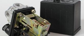
The relay design is a small-sized block equipped with receiving pipes, a sensing element (spring) and a membrane.
Mandatory subassemblies include an unloading valve and a mechanical switch.
The pressure switch sensing unit is made up of a spring mechanism, the compression force of which is changed by a screw.
According to the factory standardized settings, the elasticity coefficient is set to a pressure in the pneumatic chain of 4-6 at, as reported in the instructions for the device.
The degree of rigidity and flexibility of the spring elements is subject to the temperature of the environment, therefore absolutely all models of industrial devices are designed for stable operation in an environment from -5 to +80 ºC.
The reservoir membrane is connected to the relay switch. During movement, it turns the pressure switch on and off.
The unloading element is located between the ejector check valve and the compression block. If the motor drive stops working, the unloading section is activated, through which excess pressure (up to 2 atm) is released from the piston compartment.
Structure of pneumatic relay symbols
The marking of the air pressure switch indicates the entire optional set of the device, design features, including information about the factory settings for the pressure differential.
Let us examine the designations in more detail using the example of devices for air ejectors RDK – (*) (****) – (*)/(*):
- RDK – series of relays for compressors;
- (*) – number of threaded ports: 1 – one port with 1/4”NPT internal thread; 4 – four connectors;
- (****) - type of housing design: T10P - version 10 with a “lever” switch; T10K – “button” switch; T18P – execution 18 with a “switch” switch; T19P - 19 s;
- (*) – factory settings of the threshold response: 1 – 4…6 bar; 2 – 6…8 bar; 3 – 8…10 bar;
- (*) – diameter of the unloading valve: the absence of a symbol means a standardized parameter of 6 mm; 6.5 mm – 6.5 mm.
The difference between the minimum and maximum pressure thresholds is set by the manufacturer and, as a rule, has a value of 2 bar.
However, it is also possible to manually adjust the range of two values – maximum and minimum, but only downward.
Technical specifications
The technical parameters of the control device are designed to visualize the maximum and minimum gas pressure, as well as the flow rate of the working medium. The highest value at the inlet/outlet for a liquefied medium is 250 atm, for liquefied fuel - 25 atm. At the output, the indicator varies between 1−16 atm.
In the design, the 220 V electric gas pressure regulator contains a sensitive mechanism that can compare the signal from the set pointer with the current value and converts the command pulse into mechanical work to move the movable plate to the neutral position. If the switching force is exceeded, the sensing element, or pilot, transmits a command to switch off to the sensors.
The pilot regulator can be astatic, static, isodromic.
Astatic
During operation, an astatic type relay experiences two types of load: active (acting) and passive (reacting). It is recommended to connect the device with a sensitive membrane to the equipment for sampling gas from the central pipeline. A device of this type adjusts the pressure of the system medium according to specified parameters, regardless of the degree of workload on the control element.
Static
The static pressure switch design kit includes process stabilizers that counteract friction and play at the system joints. Static devices form equilibrium indicators that differ from the permissible values of the rated load. The control process is activated by an acting force along a damped amplitude.
Izodromny
The isodromic industrial relay is automatically switched on when the pressure deviates from the set value. The 380 V pilot element reacts to real pressure gauge readings that differ from the permissible norm. To relieve the pressure, the regulating element independently reduces the indicators to the optimal operating parameter.
Types of shutters
Important parts of 220 V throttle bodies are single-seat valves, valve valves, diaphragm valves, butterfly valves, double-seat valves, and hose valves with rigid or elastic seals. If the tightness of unbalanced valves of industrial systems decreases, repair of the 380 V valve is carried out by a mechanical workshop after preliminary diagnosis of all parts and mechanisms.
Maintenance of control devices is carried out in accordance with the plan approved by the product manufacturer and the standards for the gas control unit. Limit adjustment values are determined by technological conditions and the specifics of the operating organization.
Each device has a serial number, a passport, and a certificate of compliance with state standards. All planned manipulations or repair work are displayed in the GRU operational log.