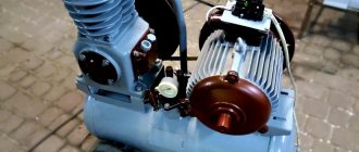
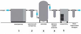
Air compressors are widely used in large and small industries, as well as for domestic purposes. These devices compress air, which is needed for air tools, spray guns, drilling rigs and other purposes. To optimize the process of its use, an air receiver (air exchanger) is used. This is a container for temporary storage under compressed air pressure. However, its capacity is not always enough. Experts advise purchasing an additional receiver for the compressor. Is it really needed? Let's figure it out.
DIY compressor receiver: instructions and assembly rules
To increase the efficiency of working with compressed air, many compressor units use receivers - containers for storing air under pressure. Based on the intensity and volume of work, containers of 50, 100 liters, sometimes more, can be used. In this article we will look at how to make an additional receiver for a compressor with your own hands, why it is needed in general, and what characteristics should be taken into account when assembling it.
Types of receivers and their scope of application
The air collector is used as part of compressor stations (CS), nitrogen, ammonia and refrigerant installations for storing and producing compressed air, nitrogen, oxygen, etc.
Air receivers are:
- linear. They are installed between the control valve and the condenser. Such receivers serve to compensate for differences in the liquid filling of evaporative equipment during heat load surges. By freeing the condenser from liquid, they create a flow of liquid agent moving evenly to the control valve. The refrigerant, maintained at the same level, becomes a hydraulic seal that prevents steam from flowing into the evaporator.
- drainage (RD or RDV). Such receivers are needed to drain liquid refrigerant from pipelines and refrigeration units during their repair and during their operation. circulation (RCZ and RCC). Reservoirs that are filled with liquid refrigerant are designed to ensure continuous operation of the circulation pump that supplies liquid to the evaporators.
- Circulating air receivers are used in pump-circulating units for supplying liquid refrigerant to evaporative systems. Air drainage receivers RD are used as protective, drainage, linear and circulation receivers; RDV vertical air receivers are used as circulation and protective receivers.
protective. They are installed below a certain level where the evaporation system equipment is located. Designed for draining liquid from liquid separators and evaporators in pumpless refrigerant supply systems.
Read also: Operating principle of a Bosch rotary hammer
You can find out the prices for air receivers sold by AIRTECHNO LLC in the price list.
What is the receiver for?
The receiver is required for the compressor to perform the following functions:
- The receiver accumulates compressed air, which helps reduce vibrations in the system. This in turn reduces the load on the base and reduces the noise level from a permanent installation;
- Stabilizes the air pressure supplied directly to the work area. In this case, differences in pressure are inevitable, since the operation of any compressor involves the injection and suction phase of air;
- Air purification from condensate. Otherwise, due to the increased pressure, the air humidity would also increase, which would lead to corrosion of the steel surface of the compressor;
- Provides compressed air supply when connecting an additional consumer, as well as during interruptions in the operation of the compressor.
To obtain large volumes of compressed air, a standard receiver may not be enough. For example, for sandblasting large surfaces, instead of a more powerful compressor, an additional receiver .
In addition, an additional receiver makes it possible to use the compressor less often, thus reducing energy consumption!
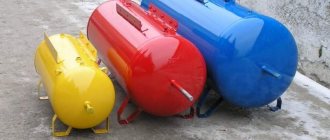
From a design point of view, the receiver is a sealed tank in most cases with a capacity of 50-100 liters. In the case of stationary units, containers up to 500-1000 liters can be used. The device is equipped with condensate drains, air filters and shut-off valves for connection to the working device and the main unit that consumes compressed air, be it a spray gun, nozzle, etc.
The container for compressed air is made of steel - usually from steel 16GA2F or 10HSND, which is resistant to corrosion. However, in the case of low-power compressors, plastic receivers, and even those made of high-strength rubber, can be used.
Paired with the installation, receivers can be equipped both vertically and horizontally. The first is in most cases used in stationary units, the second - in mobile ones. Each type offers its own pros and cons. For example, horizontal receivers require a shorter pipeline because they are more compact, but vertical ones are much easier to drain condensate.
How it works?
Let's look at how the intake manifold receiver works. The fuel injectors or carburetor spray fuel into the receiver's downpipe. Due to electrostatic force, gasoline droplets will collect into larger ones in the air or settle on the walls. These actions are undesirable because they lead to incorrect mixture formation. The better the gasoline is atomized, the more completely and intensely it will burn in the chamber. Therefore, in order to eliminate negative factors and ensure the highest quality spraying, the internal parts of the receiver are made unpolished. At the same time, the surface is not excessively rough, since this can cause greater turbulence and lead to a drop in engine power.
The inlet receiver must have a certain shape, capacity and length. The best option is an equal-length collector. All of the above parameters are calculated when developing a specific power unit. The manifold ends with air channels that direct the flow of oxygen to the internal combustion engine valves. On diesel units with direct injection, the air flow swirls and enters the cylinder. In the latter, mixing with fuel already occurs.
Source
Deciding on the parameters
In addition to capacity, the compressor receiver can be characterized by the following parameters:
- Requirements for the location (within air contaminated with mechanical particles, for example, near circular saws, away from explosive, flammable materials and heat sources).
- Working conditions (relative air humidity should not be more than 75-80 percent, temperature around 15-40 degrees).
- Maximum air humidity levels.
According to the requirements of PB 03-576-03, it is prohibited to use receivers that have defects on the surface, such as corrosion, dents and cracks, as well as those that have not passed the performance test of the container walls.
The characteristics of the receiver for the compressor are selected as follows. The first step is to determine the maximum and minimum pressure values, the duration of operation and the required compressed air consumption. The next step is to find the required data using a table with online calculations, which can be easily found on the Internet upon request. For example, in the case of a maximum/minimum pressure drop of 4/3 atm, a maximum load duration of 5 minutes and an air flow rate of 0.1 m 3 /min, the optimal volume of the receiver tank will be 500 liters.
This method focuses on the time during which the receiver will be completely empty. However, there is a simpler tabular method that allows you to correlate the power consumption of the compressor with the volume of the receiver. Among them, it is worth highlighting the most commonly used ratios:
- Up to 550 liters for compressors up to 20 kW;
- Up to 300 liters for 10 kW models;
- And up to 100 liters for 5 kW products.
If necessary, intermediate values can be calculated by interpolation. There are also experimental dependencies. According to one of them, the capacity of the receiver tank should not be less than the compressor performance during 8 seconds of continuous operation. In this case, the volume of the tank at an air flow rate of 400 l/min can be calculated as follows:
V = (400*8)/60=53.33 l
Rounding up we get 54 liters.
Do-it-yourself additional receiver for a compressor
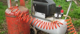
Some work in a workshop or at home may require increased consumption of compressed air, which household compressors are not capable of providing. One possible solution would be to place an additional receiver for the compressor. The cost of such a device, based on volume, will be 12-15 thousand rubles if you buy it in a store, but nothing prevents you from saving money and making the receiver yourself. An additional advantage in favor of the second solution is that most of the models offered in the store are designed for standard compressors, which is why their price is so high!
The connection of the additional receiver is usually carried out in series with the main one, and therefore, depending on the required volume, a regular fire extinguisher body or a cylinder left over from liquefied gas may be suitable for operation.
As in the case of assembling a barbecue from a gas cylinder, making a homemade receiver begins with thoroughly cleaning the cylinder from gas residues. For this purpose, the first step is to remove the input valve. It is important to note that you cannot remove the valve using a power tool , as there may be gas residues inside!
After this, the bottle is filled with water for a day. Next, threaded plugs with gaskets are screwed into the container or tubular splitters for hoses are welded. Finally, the cylinder should be treated with weatherproof paint !
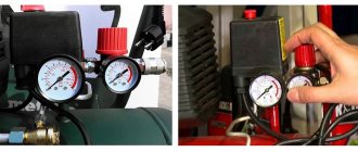
You can install a condensate drain at the bottom of the container; it would also be useful to have a pressure gauge or pressure switch on the receiver. In the case of a condensate drain, its size should be selected based on the dimensions of the connecting thread, operating pressure and compressor performance. The average cost of condensate traps is around 2.5-3 thousand rubles.
Below in the photo you can see the finished additional receiver for the compressor, placed on top of a tripod welded from a steel rod.
When working with a homemade device, you should consider the following points:
- As the pressure decreases, the operating time will have to be reduced from the usual 75-80 percent to 50-60. For lower values, it is not practical to use a self-assembled element;
- Before putting a full load on the compressor electric motor, you should first check the possibility of its operation in tandem with an additional receiver! For this purpose, the compressor drive is started at idle, after which, during prolonged operation (more than 20 minutes), the pressure difference is measured with a flow meter. In this case, the additional receiver is suitable for operation if the pressure during testing does not fall below the minimum value;
- In the case of an additional tank, the installation of a condensate drain is considered mandatory.
Well, now you know what a receiver is for, what it is, what characteristics it has, and also how to install an additional cylinder to the main tank. We hope the tips presented will be useful to you. Good luck!
How to connect an additional cylinder to the compressor receiver. Additional receiver for compressor
25 Jan 2012, 14:12
queens to a
- what's the question?
take it and cut it into the air system. The receiver is vertical. The drain valve is at the bottom, if anything. The entrance is from above, the exit is also from above. Just space it further apart from each other. 25 Jan 2012, 14:58
Vyacheslav
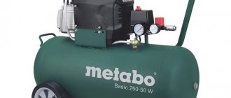
- I want to make an exit through the reducer, through the so-called frog. My compress is similar to the one shown above, when it is filled to 90 points it turns off, and when the pressure drops it turns on. I recently removed the head and cleaned it of paint, for the first time in a year and a half. What to do with the filter, it has a simple foam rubber in it. There is no hood, but it’s in the same place where I paint. I wanted to take the hose from the air vent outside, but the air there is now cold, if you put smaller foam rubber, there will be excess overheating, which means wear and tear on the parts. Here's the problem! and what to do?
26 Jan 2012, 09:49
automaster
- I read somewhere that an additional receiver should have an entrance from below or from the side at the very bottom, and an exit from above and, accordingly, there should be a tap for draining condensate.
26 Jan 2012, 18:59
trin
- so that the air enters in a spiral.
that's right. I heard it too and even saw it. 26 Jan 2012, 21:39
queens to a
- I did this. I modified the compressor head. I screwed in the pipe three quarters. Then the flange connection. I put a stainless steel mesh between the contact planes. Then I put a yellow reinforced hose (it’s being built at the market, where they sell it for water supply). It’s the third part to the muffler can) and then to the street. and the whole thing ends with a filter from a truck. A muffler is required. Otherwise it’s impossible to work. The main noise comes from the disruption of flow at the inlet of the compressor. The compressor is in my basement. And after such modifications I hear noise from the rolling bearings in the electric motor. And on the street you can hear a company smoking a hookah, a dull low gurgling sound. The mesh is needed so that nothing gets into the compressor from the muffler. After all, you know our manufacturers
Jan 29, 2012, 11:54 p.m.
Valera
- about the receiver.
for full painting, at first it seems to help, but the current pressure drops below the required level, and then the chill begins with the expectation of pumping and the desire to continue (with the receiver, the pumping time increases). In my opinion, I need a compressor with the required performance. or one more until needed. more comes out than goes in, which then is the essence of the receiver. the compressor has to move more in the intervals. RECEIVERS ARE INSTALLED TO COOL THE AIR TO REMOVE MOISTURE AND EVERYTHING. I have an old Soviet compressor and it has two small pipes in place of the receiver. there was no automation, I was constantly pumping the HLVP sprayer in my eyes. I installed the automatic system (pumps up to 7 atm and off to 5 drops on. The pipes are probably 10 liters in volume) there were surges in pressure, I installed the receiver at 50 liters, everything was correct, a total of 60 liters in the receiver. compressor output output is like 400 liters, do it yourself 01 Feb 2012, 23:27
queens to a
- a receiver to smooth out pressure surges. And a dehumidifier should cool the air. You have a compressor along the way, like mine, CO. It produces 500 liters per minute. The operating pressure is 6 atm. Spare the valve. And they are afraid of dirt.
01 Feb 2012, 23:31
Valera
- Pressure surges are leveled by a good pressure regulator after all the dryers and separators, and immediately in front of the hose, put 3 points so it will blow out 3, but if it drops below 3, no receiver or regulator will help (you won’t bother with air for the whole painting).
thank you, at least I’ll know what the compressor is called on the Internet, analogue to K24M 01 Feb 2012, 23:43
queens to a
- Do you have an automatic gearbox?
monitors pressure in the receiver? 02 Feb 2012, 03:33
Vyacheslav
- We had the same compress at our station, we used it as a pneumatic tool, it was a beast of a compress. And for the painting room (and we also made plastic windows) they have everything pneumatic, so there was a Russian compressor, a big one with three belts on the engine, a receiver that was probably about a ton liters. In the painting room there was a gearbox, set to 6 points output, on a pulver a sump with a monometer (all the equipment is SATOVSKY and the sprayers too, you set the pressure on them yourself. There were no pressure surges. But I have a weak compress and the pressure drops, it turns out an additional receiver. I don’t need it, but I need a good reducer, right?
02 Feb 2012, 05:27
02 Feb 2012, 09:04
02 Feb 2012, 09:11
Vyacheslav
- Or maybe turn off the shut-off valve altogether, or set it to turn on the compress earlier?
02 Feb 2012, 09:54
queens to a
- if the receiver has 6.5 points and you set 3 points on the reducer, then when the pressure in the receiver drops to 5 points, the pressure on the same reducer will already be 2.5. The compressor should block the air flow.
About the modification of the collector
Tuning the VAZ intake receiver is a very popular topic. This operation has two directions. This is the refinement of the inner surface and overcoming the negative influence of the element’s shape. If the latter is asymmetrical, then most of the air will enter the first cylinder, and less and less oxygen will penetrate into all subsequent ones. But symmetrical also has disadvantages. Here the air will enter in the greatest quantity into the middle cylinders. Modifications to the VAZ-2114 intake receiver in this case consist of replacing the standard manifold with a multi-throttle intake system. Here the air flows no longer depend on each other. Accordingly, the same amount of oxygen enters each cylinder.
You can modify the intake receiver of the VAZ-2112 in another way. So, some grind the inner surface. By eliminating some of the highs and irregularities, you can ensure a more uniform air supply to the engine. But as practice shows, this modification does not bring a significant increase in power. A more effective solution is to install chokes. However, this should only be done when installing a turbine, otherwise tuning will not be justified.