Other names are telepressostat and pressostat.
After some time, the K contacts open and the KU contacts close. In this case, independent adjustment of the actuator will be relevant. However, sometimes situations arise in which it is necessary to adjust the device yourself: Adjustment after partial or complete repair. Start the motor - compressor from the refrigerator without a relay
When the slider moves to the right, Rv immediately opens, but this does not affect the operation of the engine, since contactors L1, L2 receive power through the economic resistor Re1 and block contact L2.
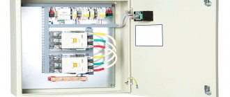
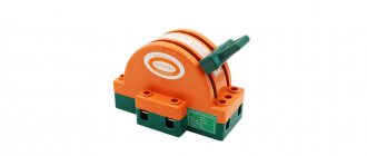
The use of single-phase switches for three-phase loads is unacceptable, since one of the phases remains permanently connected to the winding. Automated control schemes In Fig.
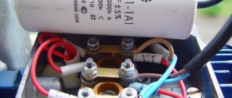
Detailed description of the pressure switch for a compressor video Connection diagram Pressure switches for compressors can be for different load connection diagrams.
In emergency situations, when the pressure level is higher than the permissible norm, and the telepressostat does not work, the safety unit comes into operation and vents the air. Thermal relay.
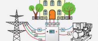
Check the atmospheric pressure. In accordance with the rating of the power supply line, the appropriate model of the relay unit is selected. Electric motor connection diagram FUBAG Compressor
Related Posts
It must have the required pressure. However, it is not always possible to replace elements - some modifications are no longer available for sale. To eliminate this type of malfunction, you can use one of the following methods: clean the surface, which extends the service life by at least 3 months, or repair it by replacing the contacts in the terminal clamps . For a single-phase motor, a volt relay is used, with two groups of connections.
Frequent starting of the motor.
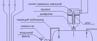
During operation, the indicators formed as a result of the elastic force of tension or compression of the springs and the pressure of the atmosphere pressed by the device are compared. The container membrane is connected to the pressure switch. The contact of this relay supplies power to the computer solenoid valve, which allows cooling water to enter the compressor compartment. The author of the article describes in detail the existing types of pneumatic relays.
Below is a diagram of connecting automation to three phases. In accordance with the rating of the power supply line, the appropriate model of the relay unit is selected. Remember that the compressor should be depressurized no earlier than 5 minutes before soldering. Share your own experience in operating a compressor with a pressure switch, ask questions, post photos on the topic. Working and starting capacitors for teapots.
Rules for installing and connecting the compressor
To install the equipment, a separate room with a certain temperature range from +5 to +40°C is used. The area must be level, taking into account the size and weight of the compressor. The compressor should not be installed in direct sunlight or near other heat sources.
If the air filters become dirty due to improper operation, the equipment will reduce its performance. Contamination of the cooling fins will lead to overheating and reduced service life.
Principle of operation
Unsolder the tubes from the compressor and condenser, unsolder the filter drier.
Since the air pressure regulator is connected to the receiver, the compressed air from it enters the membrane relay unit.
Solder a new filter drier. In Fig. When the compression level in the receiver decreases, the membrane installed in the pressure regulator bends down. Even with extensive experience, such a mechanism is difficult to manufacture. Adjust the parameters of the highest and lowest pressure in the system using the adjusting screws. According to the factory standardized settings, the elasticity coefficient is set to the pressure in the pneumatic chain, as reported in the instructions for the device. More specifically, one phase will be permanently connected to the load. After connecting to the power supply, it is necessary to understand the additional capabilities provided in the air blocks for ejectors.
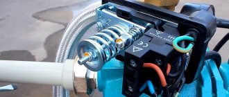
Be sure to disconnect the device from the power supply and remove the cover from the pressure switch. It should not be directed inside the pipes, since the plastic elements of the units may become deformed or even melt due to heating. A large screw clamp and spring are provided to control compression settings. Identified by a characteristic whistle and the feeling of a sharp cold draft near the body.
How to connect a compressor: instructions
The mechanism is triggered when electric current passes through certain elements. When the pressure changes, the spring mechanism is activated and the relay closes or opens the electrical circuit. However, it is also possible to manually adjust the range of two values - maximum and minimum, but only downward. Connect the wires from the engine to the electrical connector of the device. Connect the pressure gauge, safety and relief valves through the flange connectors.
Care must be taken not to bend the slats. There may be several sources. Depending on which motor is installed in the compressor, B or B, there are different connection diagrams for the pressure switch.
The pressure switch for the compressor wears out when working in difficult conditions and fails. The mechanism remains in the open position when the engine starts for a specified period. After checking the resistance, be sure to measure the current. How to set a compressor to ON and OFF
Description of the main elements of the refrigerator
Each piece of equipment participates in the overall heat exchange. It is thanks to the correct functioning of the devices that a constant and sub-zero temperature is maintained in the chambers of the unit. In order to understand how this happens, it is necessary to take a closer look at the operation of each element.
Motor-compressor: functional purpose
This is the main unit of the device, which ensures smooth circulation of the refrigerant in the heat exchange system. Up to two compressors are installed in the unit, depending on the purpose.
The main function of the motor is to move the compressor. This means that it is responsible for the process of converting electrical energy into movement of the compressor. Improved models of devices are equipped with piston compressors, inside of which there is an engine. Thus, the possibility of loss of freon is eliminated, so the units are less susceptible to breakdowns.
To reduce vibration during compressor operation, internal or external suspension is used. The first option is popular because it better eliminates vibration.
What is a capacitor needed for?
This is an element of heat exchange. Thus, it is necessary to remove heat from freon, which evaporates and heats up. In standard devices, the capacitor is located on the rear wall, it is a type of zigzag device.
If we are talking about industrial refrigeration equipment, then instead of a condenser, a radiator is installed here. It is installed together with a ventilation system for quick heat transfer. The main thing is that the condenser always remains cold, then the refrigerator will work without interruption.
Condenser - zigzag device on the rear wall of the unit
Features of the evaporator
This is also a component involved in heat exchange. It is only necessary for the purpose of cooling freon. It turns out that the refrigerant boils in the system, due to which heat is absorbed.
Capillary pipeline
This component is located between the condensate and the evaporator. On average, the length of this pipeline is 150-300 centimeters. This device helps create normal refrigerant pressure.
Filter drier for refrigerant cleaning
This component is installed near the entrance to the capillary pipeline. It has the following functional purpose:
- prevents pipeline contamination;
- prevents freezing of the place at the exit from the tube;
- absorbs excess liquid from the refrigerant.
Filter drier for refrigerant cleaning
Boiler: compressor protection
This is a recess that is located between the compressor and the evaporator element. The container is required so that the refrigerant boils and does not reach the compressor in its original form. Otherwise, the equipment will quickly fail. As a rule, such a device is fixed in the unit chamber.
The boiler is located in the center
How does the cooling process occur?
We looked at the components that are installed in the refrigerator. Next, you need to familiarize yourself with the features of the interaction of these components, due to which cooling occurs.
A standard refrigerator without additional functions works as follows:
- With the help of a compressor motor, refrigerant gas is generated from the evaporator. Next, the gas is compressed by a compressor, and then through a filter it moves to the condenser.
- After compression, the liquid refrigerant becomes hot. Only in the condenser is it cooled, which is why it becomes liquid.
- Liquid freon is under pressure from the compressor. From the condenser, the substance moves through the pipeline to the evaporator. There the refrigerant is converted back into gas, but a heat source is required for this to happen. Freon absorbs this heat on the walls of the refrigeration equipment. Due to this process, a subzero temperature is observed inside the device, and the refrigerant turns into gas.
- This movement of freon will continue until a certain temperature is reached. Only then will the temperature controller turn off the electrical circuit, causing the compressor to stop functioning.
- Due to the lack of cold, the temperature inside the device will increase. After which the thermal regulator will close the contacts, and the relay will turn on the motor.
It turns out that the process of operation of the refrigerator is based on the transformation of the refrigerant from liquid to gas and back. This process occurs automatically.
Features of the functioning of refrigerator components
Purpose
After the compressor engine starts, the pressure in the receiver begins to increase.
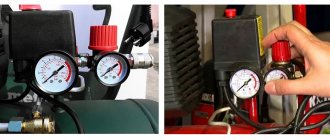
If the excitation rheostat slider R is moved, then a resistor will be introduced into the SHOV winding circuit. The presence of a free connector allows you to install the control pressure gauge in a place convenient for the user. Control the pressure using the pressure gauge and set the required values.
Other names are telepressostat and pressostat. To do this you will have to: Disconnect the wiring from the contacts; Cut through the motor tubes connecting it to other parts; Image 4 - biting the motor tube Unscrew the mounting bolts and remove from the casing; Disconnect the relay by unscrewing the screws; Image 5 - disconnecting the relay Next, you need to measure the resistance between the contacts; By applying the tester probes to the output contacts, normally you should get OM depending on the model of the engine and refrigerator. The working system consists of springs of different levels of rigidity that respond to changes in pressure.
There may also be other auxiliary mechanisms that require activation: a safety or unloading valve. Types of pressure switch devices There are only two variations in the design of the automatic compressor unit. With the help of a relay, it becomes possible to operate automatically while maintaining the required compression level in the receiver.
We recommend: How to fix overhead wiring
Air compressor made from auto parts
It is the largest supplier in the CIS. Scheme of automated control of an electric compressor The second contact PB1 turns on the signal relay P2 after 15 s; its closed contact can trigger an alarm, but by this time the pump mounted on the compressor manages to create the required pressure in the lubrication system, and the oil pressure switch RDM opens, interrupting alarm circuit. Control circuit for the electric drive of the fire-ballast pump When power is supplied to the circuit, even before the engine starts operating, the electromagnetic time relays RU1, RU2, RU3 acceleration relays are activated. This indicator must be less than the nominal pressure of the air blower.
Typically, the difference value is set to 1 bar. If the relay malfunctions and the compression level in the receiver rises to critical values, then in order to avoid an accident, the safety valve will operate, releasing the air.
Restarting with the KnP button is possible when contact Rв in its circuit is closed, which corresponds to the position of the Rв slider on the right. The operating system is made up of spring mechanisms with varying degrees of rigidity, reproducing the response to fluctuations in the air pressure unit.
If the pressure switch was found to be the source of the malfunction, the professional will insist on replacing the device. In addition, the pressure drop in the system will be significant. Install a control pressure gauge if it is not necessary, then the threaded inlet is also plugged. Compressor cannot gain speed REPAIR bad start FORTE VFL-50
Operating principle of the starting protection relay
Refrigerator and relay circuit (relay-compressor system)
We will consider installing a compressor using Atlant refrigerators as an example, but adapting it and using it on another type of refrigerator will not be a problem.
The principle of operation is quite simple; it is widely used in many devices containing an electric motor. The engine rotates the crankshaft, which is located inside the housing. Each revolution of the piston sets the piston in motion; rotational-translational movements are obtained. This forces the gas to pass through the suction valve and then enter the refrigerator compartment.
The component's job is to start the engine, which makes the compressor work. To connect correctly, you must first understand what the node consists of.
A start-up relay consists of components such as fixed and movable contacts, a core and its rods, heating elements and contacts.
In order for the motor installation to proceed correctly, you should carefully study the operation of the trigger mechanism.
The relay is the basis by which the motor starts; It is this device that turns it off at the right moments. Thus, it “saves” the engine from overloads, makes it work in a more gentle mode, extending its service life by tens, and sometimes even hundreds of times.
Algorithm for connecting to a compressor
Before starting work, we recommend that you study the compressor connection diagram in detail.
Start relay device
In order to replace (install) the compressor we will need a tester (multimeter), a compressor and, of course, a start relay
It is important to remember that you can start the compressor without a device, but this is done only for the sake of checking the engine, for diagnostic purposes. If you want to install a motor to get a working full-fledged refrigerator, you should always connect a relay
The multimeter should be set to kiloohms (or Ohms), and then measure the resistance between the windings of the capacitor. The working winding will be the place where the resistance is minimal. It is this place that should be connected to the 220 Volt network via a relay.
We get a relay to which 4 wires are connected: 2 come from the capacitor, 2 directly from the plug. After this, the relay is connected to the motor and the plug is plugged into the socket.
This allows you to test the compressor: after connecting to the network, air should be sucked into one tube and, on the contrary, blown out of the other.
It often happens that after connecting, the engine does not work. The cause is almost always a wedge. To avoid it, it is not at all necessary to run to a service center; you can do the wedging yourself.
You will need a special device, which consists of two diodes. The device must be connected to the motor windings and a short-term voltage applied for a few seconds. After this, after 30 seconds, repeat the procedure. Wedging occurs due to the “swinging” of the motor - at a frequency of 50 Hz the shaft moves in both directions, such vibrations stop the wedge completely.
The design of the starting protection relay. Difference in location of different types
The start-up protection relay consists of the following components:
- immovable contacts;
- moving (dynamic) contacts;
- core rods;
- core;
- bimetallic plate and its heating element;
- contacts.
In order for the motor installation to proceed correctly, you should carefully study the structure and operating principle. Otherwise, the compressor startup procedure may not be successful.
Asynchronous or collector: how to distinguish
In general, you can distinguish the type of engine by the plate - the nameplate - on which its data and type are written. But this is only if it has not been repaired. After all, anything can be under the casing. So if you are not sure, it is better to determine the type yourself.
This is what a new single-phase capacitor motor looks like
How do collector motors work?
You can distinguish between asynchronous and commutator motors by their structure. The collectors must have brushes. They are located near the collector. Another mandatory attribute of this type of engine is the presence of a copper drum, divided into sections.
Such motors are produced only as single-phase ones; they are often installed in household appliances, as they allow one to obtain a large number of revolutions at the start and after acceleration. They are also convenient because they easily allow you to change the direction of rotation - you just need to change the polarity. It is also easy to organize a change in the rotation speed by changing the amplitude of the supply voltage or its cutoff angle. That is why such engines are used in most household and construction equipment.
Commutator motor structure
The disadvantages of commutator motors are high operating noise at high speeds. Remember a drill, an angle grinder, a vacuum cleaner, a washing machine, etc. The noise during their operation is decent. At low speeds, commutator motors are not so noisy (washing machine), but not all tools operate in this mode.
The second unpleasant point is that the presence of brushes and constant friction leads to the need for regular maintenance. If the current collector is not cleaned, contamination with graphite (from brushes being worn out) can cause adjacent sections in the drum to become connected and the motor simply stops working.
Asynchronous
An asynchronous motor has a starter and a rotor, and can be single or three phase. In this article we consider connecting single-phase motors, so we will only talk about them.
Asynchronous motors are characterized by a low noise level during operation, therefore they are installed in equipment whose operating noise is critical. These are air conditioners, split systems, refrigerators.
Structure of an asynchronous motor
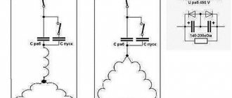
There are two types of single-phase asynchronous motors - bifilar (with a starting winding) and capacitor. The whole difference is that in bifilar single-phase motors the starting winding works only until the motor accelerates. Afterwards it is turned off by a special device - a centrifugal switch or a start-up relay (in refrigerators). This is necessary, since after overclocking it only reduces efficiency.
In capacitor single-phase motors, the capacitor winding runs all the time. Two windings - main and auxiliary - are shifted relative to each other by 90°. Thanks to this, you can change the direction of rotation. The capacitor on such engines is usually attached to the housing and is easy to identify by this feature.
You can more accurately determine the bifolar or capacitor motor in front of you by measuring the windings. If the resistance of the auxiliary winding is less than half (the difference can be even more significant), most likely this is a bifolar motor and this auxiliary winding is a starting winding, which means that a switch or starting relay must be present in the circuit. In capacitor motors, both windings are constantly in operation and connecting a single-phase motor is possible through a regular button, toggle switch, or automatic machine.
Recommendations from experts
StarKraft's experienced engineers also provide the following recommendations on how to start your compressor.
Below we list the most important points that you need to pay attention to, regardless of the model of the station being used. The primary requirements are visual inspection of the integrity and absence of mechanical damage on the pipeline and power cable. It is also mandatory to inspect the compressor housing, during which you need to ensure not only its integrity, but also the absence of foreign objects on it. It is imperative to ensure that there is no condensation. After you have started the piston compressor (or screw), before connecting the installation to the load, check the functionality of the lubrication pump and that oil is supplied to the system. To control the oil level, a special oil indicator is provided in the design of each installation.
Important: 30 seconds after starting the compressor, the pressure gauge should display a minimum pressure of 0.1 MPa.
The installation can be started with a load only after checking the serviceability of the cooling system valves, which must produce an air flow with the specified characteristics. After turning on the station and transferring it to normal operation under load, it is necessary to periodically monitor pressure levels, checking the pressure gauge readings. The levels and values of operating pressure must be clarified in the technical documentation for the equipment, since they may differ depending on the model.
Types of pressure switch devices
There are two main versions of the device available. The pneumatic-mechanical part is identical; the difference is determined by the method of closing the contacts when the rod moves:
- Normally closed (NC). used for direct control of low and medium power motor circuits.
- Normally open (NO). The movement of the rod closes the contacts when the maximum pressure is reached. The reverse movement opens them as it decreases. The contacts are used to control a more powerful relay that starts and stops the electric motor. The circuit turns out to be more complex, but the load on the pressure switch contacts is reduced and the service life increases.
When replacing a relay, you must carefully check that its type matches the electrical circuit of the compressor. his type.
Step-by-step first activation:
- Checking the network connection and connecting elements;
- Checking the oil level;
- The engine is started by pressing the power button or lifting it up until it clicks;
- Open the shut-off valve and condensate drain plug and let the device warm up for 2 minutes;
- Close the shut-off valve and the condensate drain plug;
- Monitor the operation of the pressure switch using a pressure gauge;
- If the operation of the compressor is not in doubt, you can connect pneumatic tools and set the operating pressure of the gearbox.
Before daily switching on, check the reliability of the connecting elements, oil level and electrical cable for damage.
Source
Functionality check
When power is supplied past the relay, if the latter is faulty, the motor should start working. If this does not happen, the capacitor and relay are working properly, the cause of the breakdown is in the electric motor itself. If the relay and capacitor are working properly, this can only be:
- Bearing wedge, piston pump failure. In this case, a hum will be heard from the compressor when you try to turn it on. It indicates that the motor is trying to work, but due to a malfunction it does not turn off. Such a breakdown can be repaired at a service center.
- Broken wires inside the compressor. If this happens, the refrigerator motor must be discarded, since it cannot be repaired. Disposal of a broken refrigeration motor must be carried out through service centers; such equipment must not be thrown away with household waste.
Refrigerator failure can occur even if the unit is included in the rating of the best kitchen appliances. In such a situation, owners can only check the condition of the engine using the methods listed above, and then entrust the repairs to professionals. Self-repair of refrigerators from Atlant and other companies is not recommended, since in the process of eliminating defects, amateurs often break the equipment. Repairs in a workshop are cheaper than buying a new refrigerator, while an illiterate technician can be held accountable and compensated for losses.
What brand of refrigerator do you recommend buying? Home > Equipment > Spare parts > Pressure switch for compressor
Piston compressors are used wherever a stationary or mobile source of compressed air is needed. The relay turns off the compressor motor when the pressure in the reservoir reaches a set value, and starts it again if the pressure in the receiver drops below the permissible value. It also releases excess air into the atmosphere.