Specifications
2.1. Made from carbon and stainless steel, with metric scale. The MG type micrometer head, which carries out the measurement, provides movement in the range of 0-25 mm. The division value is 0.01 mm. The permissible measurement error is ±3 µm. Diameter of the connecting part of the stem, mm – 15h7.
2.2. Technical characteristics are given in table 1.
Table 1 - Technical characteristics of GM micrometric depth gauges
| Model | Measuring range, mm | Reading value, mm | Number of measuring rods, pcs |
| GM-25 | 0-25 | 0,01 | 1 |
| GM -50 | 0-50 | 0,01 | 2 |
| GM -75 | 0-75 | 0,01 | 3 |
| GM -100 | 0-100 | 0,01 | 4 |
| GM -150 | 0-150 | 0,01 | 6 |
| GM -200 | 0-200 | 0,01 | 8 |
| GM -300 | 0-300 | 0,01 | 12 |
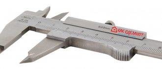
Vernier depth gauges
Depth gauges of this type make readings using a rod with divisions. The division value of the depth gauge can be from 0.05 mm to 0.1 mm. The tool is in many ways similar to a caliper, the difference is that there are no movable jaws on the depth gauge rod. The design of the depth gauge includes a frame with a measuring surface and a rod made of hard alloy with a measuring surface. There is a vernier on the frame, and the rod is equipped with a recessed scale, which virtually eliminates wear of the scale during operation. The coating of the rod and vernier scales is matte chrome; this feature ensures that there is no glare during operation.
The depth gauge works according to the following principle: the working part of the tool rod is inserted into the hole to be measured, the frame is lowered all the way and fixes it, after which the readings are taken. The most widely used instruments among the depth gauges are the ShGTs (digital depth gauges), ShG and ShGK models.
Design and principle of operation
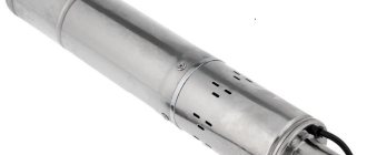
5.1. Micrometric depth gauge is a measuring device used to measure linear dimensions using the contact method. The operating principle of the micrometer head is based on the movement of the screw along the axis as it rotates in a stationary nut. The movement is proportional to the angle of rotation of the screw around the axis. Full revolutions are counted on a scale marked on the stem of the micrometer head, and fractions of a revolution are counted on a circular scale marked on the drum.
5.2. The base of the micrometric depth gauge is placed on the surface from which the size is determined.
Rice. 1. Micrometric depth gauge: 1 - base; 2 - stem; 3 - measuring rod; 4 - drum; 5 - ratchet; 6 - stopper.
5.3. Micrometric depth gauges are equipped with replaceable measuring rods for each measurement range. The readings are measured accordingly on the scale of the micrometer head. The accuracy of the measurements is determined by the accuracy of the measurement using a micrometer head.
5.4. Dimensions are measured based on readings taken from the micrometer head and the replaceable measuring rod.
Description: Micrometric depth gauge type GM GOST 7470-92
The depth gauge is designed to measure the depth of grooves, holes and the height of ledges up to 150mm.
Depth gauges are available with two measurement limits: 0-100 and 0-150mm.
Depth gauges with measurement limits of 0-100 mm are equipped with replaceable measuring rods for measurements in the range of 0-25, 25-50, 50-75, 75-100 mm and two length adjustment measures of 25 and 75 mm.
Depth gauges with measurement limits of 0-150 mm are equipped with replaceable measuring rods for measurements in the range of 0-25, 25-50, 50-75, 75-100, 100-125, 125-150 mm and three length adjustment measures of 25, 75 and 125 mm.
The principle of operation of the depth gauge: by rotating the micrometer head drum, the measuring rod is imparted a translational movement until it comes into contact with the surface being measured. In the range from 0 to 25 mm, measurement is carried out by the direct method using a reading device, in the range from 25 to 150 mm - using installation measures (included in the depth gauge kit), and the depth gauge is set to zero using the installation standards. The depth gauge consists of a base with a rectangular-shaped supporting measuring surface into which a micrometer head is pressed. Replaceable measuring rods are installed in the hole of the micrometer screw, which provide the required measurement range.
Control and measuring instruments (instruments) are equipment without which it is impossible to imagine modern production today. Measurements are required at every production stage and in a wide variety of industrial applications. That’s why the measuring instruments are so diverse, including micrometric depth gauge type GM GOST 7470-92, micrometers, mikators, straight edges and straight edges, pedometers, inclinometers, thickness gauges, hardness gauges, microscopes, calipers, etc.
Operating procedure and maintenance
8.1. During work and at the end of it, wipe the micrometric depth gauge with a cloth soaked in an aqueous-alkaline solution of coolant, and then dry with a clean cloth.
8.2. Upon completion of work, apply a thin layer of any technical oil to the surface of the micrometric depth gauge and place it in the case.
8.3. During operation, do not allow rough impacts or falls to avoid bending and other damage, scratches on the measuring surfaces, and friction of the measuring surfaces against the part being tested.
Setting zero on a micrometer or how to calibrate correctly
Not many people know how to use a micrometer, and even fewer people know that before starting work the device must be set to zero. What does this mean, when and how to do it, we will find out further.
The device must be set to zero when calibration reveals that the device is showing inaccurate data. Zeroing is what calibrates the instrument and is very easy to do. To do this, you need to pick up the device and check that the zero mark on the moving drum matches the central mark on the stem. To perform the test, the paws must be brought together until the ratchet operates. After this we do the following:
- Let's check the match. If the zero does not coincide with the mark on the fixed scale, then we proceed to adjustment manipulations
- To do this, you will need to use a special hex key or do the work manually, which depends on the modification
- First we bring the sponges together
- Using a switch, we fix them in a stationary state with a sponge
- Loosen the ratchet fastening, and then move the drum until zero coincides with the scale on the stem
- Tighten the ratchet while holding the drum in this position
At this point, zeroing the micrometer is considered complete. The video below shows the principle of calibrating a micrometer using a hex wrench. The principle is almost identical, only you need to unscrew the drum mount with a wrench in order to be able to align its zero with the center line.
Storage rules
9.1. Store the micrometric depth gauge in a case in a dry, heated room at an air temperature of +5 to +40˚С and a relative humidity of no more than 80% at a temperature of + 20˚С.
9.2. When storing the product for a long time, in order to avoid corrosion, in addition to lubricating the micrometric depth gauge with oil, it must be wrapped in water-repellent paper.
9.3. The air in the room should not contain admixtures of aggressive vapors and gases.
ACCEPTANCE
3.1. To check the compliance of depth gauges with the requirements of this standard, state tests, acceptance inspections, periodic tests and reliability tests are carried out.
3.2. State tests - according to GOST 8.383* and GOST 8.001*.
* PR 50.2.009-94 applies on the territory of the Russian Federation.
3.3. During acceptance inspection, each depth gauge is checked for compliance with the requirements of paragraphs. 1.8, 1.9, 2.2 - 2.4, 2.6, 2.8, 2.10, 2.11.1 - 2.11.3, 2.12, 2.17 and 2.18.
3.4. Periodic tests are carried out at least once every three years on at least three depth gauges of each type and accuracy class from those that have passed acceptance control for compliance with all the requirements of this standard, except for the requirements of paragraphs. 2.13 - 2.16.
The test results are considered satisfactory if all tested depth gauges meet all tested requirements.
3.5. Confirmation of reliability indicators (clauses 2.13 - 2.16) is carried out at least once every three years according to reliability testing programs developed in accordance with GOST 27.410 and approved in the prescribed manner. It is allowed to combine reliability tests with periodic tests.
Links[ | ]
- Great Soviet Encyclopedia: / Ch. ed. A. M. Prokhorov. — 3rd ed. - M.: Soviet Encyclopedia, 1969-1978.
- GOST 6507-90 “Micrometers. Technical specifications"
| Measuring instruments | |
| |
| Micrometers |
|
Links[ | ]
- Great Soviet Encyclopedia: / Ch. ed. A. M. Prokhorov. — 3rd ed. - M.: Soviet Encyclopedia, 1969-1978.
- GOST 6507-90 “Micrometers. Technical specifications"
| Measuring instruments | |
| |
| Micrometers |
|
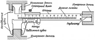
What is the difference between a depth gauge and a caliper?
Structurally, the depth gauge is similar to a caliper, but unlike it, it does not have jaws on the rod. The design of the device includes a rod, a frame with a vernier and a screw. The frame division price is 0.5 mm, for the vernier it is 0.05-0.1 mm (GOST 162-90). The scale on the frame is intended for measuring integers; using a vernier, measurements are taken with an accuracy of hundredths of a millimeter. The vernier is located in the frame slot and has 10, 20, 50 divisions. The frame is secured using a screw while taking measurements. A micrometric pair consists of a screw and a nut.
The interval of one vernier division depends on the modulus value (1, 2, 3, 4, etc.). An increase in the module leads to an increase in the length of the vernier, so most often the tool is made with a module equal to 2. The interval between divisions on the vernier is always a multiple of the interval between divisions of the main scale on the rod. All strokes are applied at the same interval. As you move up the scale, the graduation lines on the vernier begin to lag behind the main scale.
Electronic depth gauge for ice fishing
Those who do not want to make a depth gauge with their own hands can purchase electronic devices. The devices help to quickly determine depth and operate on the same principle as echo sounders. Such depth gauges emit and receive ultrasonic signals that travel through water at a speed of one and a half kilometers per second. The simplest model of the device can determine depths of up to 60 meters.
With the help of electronic depth gauges, depth can also be determined through ice. In addition, they display air and water temperatures. However, searching for fish using such devices is impossible. Therefore, such devices are much cheaper than echo sounders. To determine the depth with an electronic device, you need to lower its sensor into the hole, and then press the button. Next, the device display will display the indicators. Since fish have the ability to pick up ultrasonic signals, it is necessary to measure the depth before you start fishing. Otherwise, there is a chance that the fish will be scared away. Then there can be no talk of any biting.
There are now improved models of depth measuring devices on the market. Such devices are more “prepared” for winter conditions; their housing is waterproof and the display is frost-resistant. They can also act through the ice and turn in different directions.
However, the most optimal device for measuring depth remains an echo sounder. This modern device helps not only to determine the depth and relief, but also allows you to find places where fish are concentrated. As a rule, the design of one echo sounder differs little from another, since the basis of these devices of each device is the same physical characteristics.
The components of the device are:
- Power source - they are either a battery or replaceable batteries.
- Electric pulse generator. A conventional power source does not have enough power to send a signal to great depths. Therefore, it is necessary to convert the weak current of the power supply into much more powerful pulses.
- Emitter with converter. It converts electrical impulses into a sound wave, which is reflected from the bottom, fish and other obstructing elements. The high-frequency signal penetrates to considerable depth, and the low-frequency signal gives a wider viewing angle of the device.
- Information processing device.
- The screen on which information is displayed.
- Other sensors.
Echo sounders for winter fishing are able to withstand low temperatures, and they are also compact, which makes them easy to move. These devices have gained recognition among winter fishing enthusiasts; they can become an indispensable assistant for both beginners and experienced fishermen.
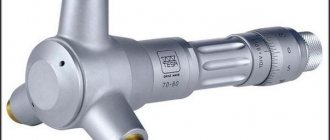
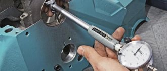
Measurement technology
First of all, it should be noted that two measurement methods have been developed:
- The absolute method consists of determining the distance between given points by placing the device inside.
- With relative technology, a sample is used to obtain the result.
It should be noted that these technologies are suitable for various types of measuring instruments. The first is used for a micrometric bore gauge, and the second for an indicator gauge.
Measurements with a first type device include the following operations:
- The approximate size of the hole being measured is set on the tool.
- The head is placed inside perpendicular to the longitudinal axis of the device.
- On both sides, the measuring surfaces are pressed against the walls by rotating the ratchet and drum.
- Tighten the locking screw and remove the tool.
- To obtain the result, add to the scale value the length of the pressure gauge head, as well as the extension if used.
When working with cylindrical holes, the tool is rocked alternately in the longitudinal and transverse directions in order to determine the maximum and minimum values, respectively.
Measurement with an indicator device also includes several stages:
- First of all, the indicator bore gauge is placed inside the hole with a rod perpendicular to the longitudinal axis of the part being measured, correcting it by gently rocking it.
- The deviation of the arrow to the right indicates a smaller diameter of the hole in comparison with the sample, and to the left indicates a larger one.
- Next, readings are taken using both indicator scales.
- Finally, the diameter of the sample is added to the obtained value.
To measure large holes, indicator bore gauges are equipped with additional extension rods.
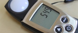
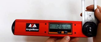
How does an electronic depth gauge work?
In accordance with GOST, a digital depth gauge consists of a rod with a frame. Unlike its mechanical brother, it does not have an additional vernier scale on the frame, but an electronics unit. The liquid crystal display and device control buttons are located on its front surface. Digital devices of the ШГЦ type have autonomous power supply. Varieties that have the function of connecting to an external device may have an independent power source or be connected to the network.
In this case, the device comes with a power supply. The permissible speed of movement of the frame, which does not reduce the accuracy of the measurements taken, must be at least 0.5 m/s. Just like when working with a digital caliper, to measure depths, the tool must be set to zero. Installation is carried out using control buttons anywhere in the measuring range. The origin is set in an absolute coordinate system.
The results obtained are displayed digitally on the display indicating the absolute value, sign, and units of measurement (millimeters, inches). When the device is connected to a computer, measurement data is also displayed on the PC monitor. Electronic devices are professional and are used to automate production processes. Because of this, they must ensure the performance of a number of functions defined by the appendix to GOST 162-90. In addition to the main functions, this list includes:
- storing the results obtained;
- preliminary input of constants;
- comparison of measurement results with established threshold values;
- performing arithmetic operations, etc.
Not all models of depth gauges of the ShGTs type have these functions. The largest number of additional functions of the tool allows for maximum automation of technological processes.
- 5
- 4
- 3
- 2
- 1