There are 2 types of single-phase asynchronous motors - bifilar (with a starting winding) and capacitor. Their difference is that in bifilar single-phase motors the starting winding operates only until the motor accelerates. Afterwards it is turned off by a special device - a centrifugal switch or a start-up relay (in refrigerators). This is necessary because after overclocking it reduces efficiency.
In capacitor single-phase motors, the capacitor winding runs all the time. Two windings - the main and auxiliary, they are shifted relative to each other by 90°. Thanks to this, you can change the direction of rotation. The capacitor on such engines is usually attached to the housing and is easy to identify by this feature.
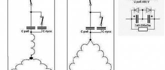
Connection diagram for a single-phase motor via a capacitor
When connecting a single-phase capacitor motor, there are several options for connection diagrams. Without capacitors, the electric motor hums, but does not start.
- 1 circuit - with a capacitor in the power supply circuit of the starting winding - starts well, but during operation the power it produces is far from rated, but much lower.
- 3, the connection circuit with a capacitor in the connection circuit of the working winding gives the opposite effect: not very good performance at start-up, but good performance. Accordingly, the first circuit is used in devices with heavy starting, and with a working capacitor - if good performance characteristics are needed.
- Diagram 2 - connecting a single-phase motor - install both capacitors. It turns out something between the options described above. This scheme is used most often. She's in the second picture. When organizing this circuit, you also need a PNVS type button, which will connect the capacitor only during the start time, until the motor “accelerates”. Then two windings will remain connected, with the auxiliary winding through a capacitor.
Operating principle
The principle of operation of an electric motor demonstrates the simplest experiment that we were all shown at school - the rotation of a frame with current in the field of a permanent magnet.
The frame with current is an analogue of the rotor, the stationary magnet is the stator. If current is applied to the frame, it will turn perpendicular to the direction of the magnetic field and freeze in this position. If you force the magnet to spin, the frame will rotate at the same speed, that is, synchronously with the magnet. We have a synchronous electric motor. But our magnet is a stator, and by definition it is motionless. How to make the magnetic field of a stationary stator rotate?
First, let's replace the permanent magnet with a current-carrying coil. This is the winding of our stator. As is known from the same school physics, a coil with current creates a magnetic field. The latter is proportional to the magnitude of the current, and the polarity depends on the direction of the current in the coil. If we apply alternating current to the coil, we get an alternating field.
A very clear analogy with a clock will help us. What vectors constantly rotate before our eyes? These are the hour hands. Let's imagine that there is a clock hanging in the corner of the room. The second hand rotates one full revolution per minute. An arrow is a vector of unit length.
The shadow that the arrow casts on the wall varies as a sine with a period of 1 minute, and the shadow cast on the floor changes as a cosine. Or a sine phase shifted by 90 degrees. But a vector is equal to the sum of its projections. In other words, the arrow is equal to the vector sum of its shadows.
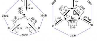
Connection diagram for a three-phase motor via a capacitor
Here, the voltage of 220 volts is distributed into 2 series-connected windings, where each is designed for this voltage. Therefore, the power is lost almost twice, but such an engine can be used in many low-power devices.
The maximum power of a 380 V motor in a 220 V network can be achieved using a delta connection. In addition to minimal power losses, the engine speed also remains unchanged. Here, each winding is used for its own operating voltage, hence the power.
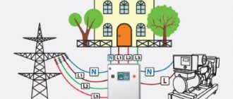
It is important to remember: three-phase electric motors have higher efficiency than single-phase 220 V motors . Therefore, if there is a 380 V input, be sure to connect to it - this will ensure more stable and economical operation of the devices. To start the motor, you will not need various starters and windings, because a rotating magnetic field appears in the stator immediately after connecting to a 380 V network.
Useful: Do-it-yourself grounding in the house: earth circuit diagram for a 220V network
Single-phase electric motor with asymmetric stator magnetic circuit
Stator
Such a single-phase motor is made with pronounced poles on an asymmetrical laminated core. Rotor
— short-circuited “squirrel cage” type.
This electric motor does not require the use of phase-shifting elements to operate. The disadvantage of this engine is low efficiency.
A single-phase motor operates using alternating electric current and is connected to single-phase networks. The network must have a voltage of 220 Volts and a frequency of 50 Hertz.
Electric motors of this type are used mainly in low-power devices:
- Household appliances.
- Low power fans.
- Pumps.
- Machines for processing raw materials, etc.
Models are available with power from 5 W to 10 kW.
The values of efficiency, power and starting torque for single-phase motors are significantly lower than for three-phase devices of the same size. The overload capacity is also higher for 3-phase motors. Thus, the power of a single-phase mechanism does not exceed 70% of the power of a three-phase mechanism of the same size.
device
Device:
- It actually has 2 phases, but only one of them does the work, which is why the motor is called single-phase.
- Like all electric machines, a single-phase motor consists of 2 parts: stationary (stator) and moving (rotor).
- It is an asynchronous electric motor, the stationary component of which has one working winding, connected to a single-phase alternating current source.
The strengths of this type of engine include the simplicity of the design, which is a rotor with a squirrel-cage winding. The disadvantages are low starting torque and efficiency.
The main disadvantage of single-phase current is its inability to generate a magnetic field that performs rotation. Therefore, a single-phase electric motor will not start on its own when connected to the network.
In the theory of electrical machines, the rule applies: in order for a magnetic field to arise that rotates the rotor, there must be at least 2 windings (phases) on the stator. It is also required to shift one winding by a certain angle relative to the other.
During operation, alternating electric fields flow around the windings:
- In accordance with this, the so-called starting winding is located on the stationary section of the single-phase motor. It is shifted 90 degrees relative to the working winding.
- A current shift can be obtained by including a phase-shifting link in the circuit. Active resistors, inductors and capacitors can be used for this.
- 2212 electrical steel is used as the basis for the stator and rotor.
Online calculation of motor capacitor capacity
| Enter data for calculating capacitors - motor power and efficiency |
There is a special formula that can be used to calculate the required capacity accurately, but you can easily get by with an online calculator or recommendations that are derived from many experiments:
The working capacitor is taken at the rate of 0.8 μF per 0.1 kW of engine power; The launcher is selected 2-3 times more.
Capacitors must be non-polar, that is, not electrolytic. The operating voltage of these capacitors must be at least 1.5 times higher than the network voltage, that is, for a 220 V network we take capacitors with an operating voltage of 350 V and higher. To make starting easier, look for a special capacitor in the starting circuit. They have the words Start or Starting in their markings.
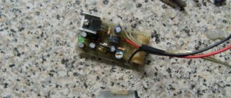
Starting capacitors for motors
These capacitors can be selected using the method from smallest to largest. Having thus selected the average capacity, you can gradually add and monitor the operating mode of the engine so that it does not overheat and has enough power on the shaft. Also, the starting capacitor is selected by adding until it starts smoothly without delays.
During normal operation of three-phase asynchronous electric motors with capacitor start, connected to a single-phase network, it is assumed that the capacitance of the capacitor will change (decrease) with increasing shaft speed. At the moment of starting asynchronous motors (especially with a load on the shaft) in a 220 V network, an increased capacity of the phase-shifting capacitor is required.
Single-phase and three-phase asynchronous motors
We agreed - three-phase commutator motors are difficult to obtain; the current section deals with asynchronous machines. We list the varieties:
- Three-phase asynchronous motors are equipped with a number of outputs from three to six working windings minus various fuses, internal relays, and various sensors. The stator coils inside are connected by a star, making it impossible to directly connect to a single-phase network.
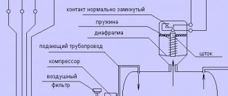
- Single-phase motors equipped with a starting winding are, among other things, equipped with a pair of contacts leading to a centrifugal limit switch. The miniature device breaks the chain when the shaft is untwisted. The starting winding catalyzes the initial stage. Further action will interfere, reducing the efficiency of the engine. The design is usually called bifilar. The starting winding is wound with double wire, reducing reactance. Helps reduce the capacitance of the capacitor - critical. A striking example of single-phase asynchronous motors with a starting winding are the compressors of household refrigerators.
- The capacitor winding, different from the starting winding, operates continuously. We will find the motors inside the floor fans. The capacitor provides a phase shift of 90 degrees, allowing you to choose the direction of rotation and maintain the desired shape of the electromagnetic field inside the rotor. Typically the capacitor is mounted on the motor housing.
- Small asynchronous motors used in hoods and fans can be started without a capacitor at all. The initial movement is formed by the flapping of the blades, or by the curvature of the rotor wiring (grooves) in the desired direction.
Let's learn how to distinguish single-phase asynchronous motors from three-phase ones. In the latter case, there are always three equal windings inside. Therefore, you can find three pairs of contacts that, when examined by a tester, give the same resistance. For example, 9 ohms. If the windings are connected by a star inside, there will be three terminals with the same resistance. Of these, any pair gives identical readings displayed on the multimeter screen. The resistance is equal to two windings each time.
Because current must flow out, sometimes a three-phase motor has a neutral terminal. The center of the star, with each of the other three wires, gives identical resistance, half that shown by the pairwise continuity. The above symptoms speak eloquently: the motor is three-phase, alien to the topic of today’s conversation.
The winding motors discussed in this section contain two. One starting or capacitor (auxiliary). There are usually three or four conclusions. If there is no capacitor decorating the case, you can try to reason, puzzled by the purpose of the contacts, as follows:
- There are four pins - you need to measure the resistance. Usually they ring in pairs. The resistance is lower - we found the main winding, connected to a 230 volt network without a capacitor. Polarity does not matter; the direction of rotation is set by the way the auxiliary winding is turned on, by switching the coils. Simply put, connect a single-phase electric motor of a characteristic type with only one main winding - in the initial period of time the shaft stands upright. Wherever you spin, there will be rotation. Beware of starting with your hand - it will break.
- We see three conclusions. Inside, the ends of the coils are connected to form a star. Neutral (circuit zero) is supplied. Regarding the other two terminals, the pairwise resistance will be the greatest (equal to both windings connected in series). The smallest value, as before, will be the working winding; the starting phase passes through the capacitor. Will provide a shift in the right direction. Typically, such a motor rotates unidirectionally; it is impossible to physically change the polarity of the capacitor. However, there is information (we’ll check the diagrams another time): by feeding the working coil with voltage through a capacitor, turning on the starting coil directly, we will perform a reverse. The possibility of connecting a 3-wire electric motor, implementing reverse rotation, is not mentioned in the literature.