Single-phase asynchronous motors are powered from a conventional 220 V alternating voltage network.
The most common design of such motors contains two (or more) windings - working and phase-shifting. The working one is fed directly, and the additional one is fed through a capacitor, which shifts the phase by 90 degrees, which creates a rotating magnetic field. Therefore, such motors are also called two-phase or capacitor motors.
It is necessary to regulate the rotation speed of such motors, for example, for:
- changes in air flow in the ventilation system
- pump performance control
- changes in the speed of moving parts, for example in machine tools, conveyors
In ventilation systems, this allows you to save energy, reduce the level of acoustic noise of the installation, and set the required performance.
Methods of regulation
We will not consider mechanical methods of changing the rotation speed, for example gearboxes, couplings, gear transmissions. We will also not touch upon the method of changing the number of poles of the windings.
Let's consider methods with changing electrical parameters:
- change in motor supply voltage
- change in supply voltage frequency
Types of commutator motors
At least two types of commutator motors are known. The first includes devices with an armature and an excitation winding on the stator. The second includes devices with an armature and permanent magnets. It is also necessary to decide for what purposes the regulator needs to be designed:
- If it is necessary to regulate with a simple movement (for example, by rotating a grinding stone or drilling), then the speed will need to be changed within the range from some minimum value, not equal to zero, to the maximum. Approximate value: from 1000 to 3000 rpm. A simplified circuit with 1 thyristor or a pair of transistors is suitable for this.
- If it is necessary to control the speed from 0 to maximum, then you will have to use full-fledged converter circuits with feedback and strict control characteristics. Usually, self-taught craftsmen or amateurs end up with commutator motors with an excitation winding and a tachogenerator. Such a motor is a unit used in any modern washing machine and often fails. Therefore, let’s consider the principle of controlling this particular engine, studying its structure in more detail.
DC brushed motor control circuit
A simple DC motor control circuit can be assembled from a field effect transistor. It plays the role of an electronic key that switches the motor power circuit after voltage is applied to the base. The electronic key remains open for a time corresponding to the pulse duration.
The PWM signal is characterized by a duty cycle, which is equal to the inverse of the duty cycle. The duty cycle is equal to the ratio of the pulse duration to the period of its supply
The speed of the motor shaft will be proportional to the duty cycle value. Therefore, if the frequency of the PWM signal is too low to ensure stable operation, the motor shaft will rotate noticeably jerkily. To guarantee smooth regulation and stable operation, the frequency must exceed hundreds of hertz.
Related materials
A three-phase asynchronous electric motor for converting single-phase voltage into three-phase: we get 380 Volts in the garage... I have several machines in my garage: wood and metal lathes, a milling machine and a circular machine. But…
A universal drive with a Pulse-Phase Control System... The regulator serves not only for smooth regulation of the speed of a DC motor, but also...
Single-phase DC drive... The development of the electric drive is based on the principle of operation of a servo drive with a single-circuit system...
Soldering iron heating regulator in the extension cord housing... One of the first circuits for a beginning radio amateur is often a thyristor power regulator...
Wind generator based on an asynchronous motor... The design of this wind generator is quite simple and reliable. This is the first attempt at remodeling...
Atmel U211B - motor speed controller from a washing machine for a home machine... My new Datagor article is devoted to the topic of converting an electric motor from a washing machine into...
Automatic microdrill speed controller from Alexander Savov... Yes, this is my drill and for some reason everyone gets scared when they see it. Well, I feel sorry for the money for a normal one...
Controlling a stepper motor from a PC... A driver for a stepper motor that is controlled from a personal computer. Hi all! Decided…
Two-channel analog cooling controller for video cards, PC or amplifier. LM35, LM358, NE555... I got two inexpensive ATI HD4870 video cards with custom Thermaltake DuOrb cooling...
Power regulator on field-effect transistors with PHI control + device for powering 110-volt equipment from 220 volts... Hello to all Datagorians and guests of Datagoria! I offer a circuit that is easy to manufacture and set up...
A perpetual encoder (valcoder) with stable positions from a stepper motor... A mechanical encoder is an easy-to-use thing, but it has some annoying disadvantages. IN…
Drilling machine for printed circuit boards based on disk drive mechanisms... Nowadays the equipment is quickly becoming obsolete. Everything that remains out of use must be put back into use!…
Regulating the rotation speed of the NV DPT by changing the main magnetic flux
This method of regulation in an independent excitation motor is implemented by means of a rheostat rreg in the excitation winding circuit.
Thus, as the resistance of the rheostat decreases, the magnetic flux of the field winding increases, which is accompanied by a decrease in rotation speed.
As r increases, the rotation frequency increases. The dependence of the rotation speed on the excitation current is expressed by the regulating characteristic
of the motor n=f(IB) at and .
From expression (29.5) it follows that with a decrease in magnetic flux Ф
rotation frequency n increases according to a hyperbolic law (Fig. 29.5,a).
But at the same time, a decrease in Ф
leads to an increase in the armature current Ia = M/(Cm*F). During the flow, the armature current reaches the value , i.e. e. the voltage drop in the armature circuit reaches a value equal to half the voltage supplied to the armature. Under these conditions, the engine speed reaches a maximum nmax. With a further decrease in flow, the engine rotation speed begins to decrease, since due to the intense increase in current Ia, the second term of expression (29.9) increases faster than the first.
With a small load torque on the motor shaft, the maximum rotation speed nmax is many times higher than the rated engine speed nnom and is unacceptable in terms of the mechanical strength of the engine, i.e., it can lead to its “overrunning”. Taking this into account, when choosing a rheostat rreg, it is necessary to ensure that when its resistance is fully introduced, the engine speed does not exceed the permissible value.
For example, for engines of the 2P series, the rotation speed is allowed to exceed the nominal by no more than 2-3 times. It is also necessary to monitor the reliability of the electrical connections in the motor field winding circuit, since when this circuit is broken, the magnetic flux decreases to the value of the residual magnetism flux Fost, at which the rotation speed can reach a dangerous value. The type of adjustment characteristics n = f(Ф) depends on the value of the load torque M2 on the motor shaft: with an increase in M2, the maximum rotation speed nmax decreases (Fig. 29.5, b
)
.
Rice. 29.5. Regulating characteristics of an independent excitation motor
The disadvantage of the considered method of regulating the rotation speed is that when the magnetic flux F
the angle of inclination of the mechanical characteristics of the engine changes.
The considered method of regulating the rotation speed is simple and economical, since in independently excited motors the current IB = (0.01 - 0.07) Ia, and therefore the losses in the control rheostat are small.
However, the control range is usually nMAX/nMIN = 2 - 5. This is explained by the fact that the lower limit of the rotation speed is due to the saturation of the machine, which limits the value of the magnetic flux Ф
, and the upper limit of the frequency is a danger of “spacing” the engine and increasing the influence of the armature reaction, the distorting effect of which, when the main magnetic flux
F
, increases and leads to sparking on the collector or to the appearance of a circular fire.
How to calculate the current and power of an electric motor?
It happens that the current of an asynchronous motor is known (from measurements in nominal mode or from the nameplate), but its power is unknown. How to calculate power in this case? Typically the following formula is used:
P = I (1.73 U cosφ η)
where: P is the rated net power on the motor shaft in W (indicated on the nameplate), I is the motor current, A, U is the supply voltage of the windings (380 V when connected in a “star”, 220 V when connected in a “delta”), cosφ, η – power and efficiency factors to take into account losses (usually 0.7...0.8).
To calculate the current based on known power, use the inverse formula:
I = P/(1.73 U cosφ η)
For motors with a power of 1.5 kW or more, the windings of which are connected in a star (this connection is most often used), there is a simple rule of thumb - to approximately estimate the motor current, you need to multiply its power by 2.
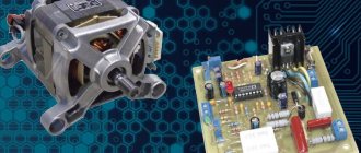
Motor design
Structurally, the engine from the Indesit washing machine is simple, but when designing a controller to control its speed, it is necessary to take into account the parameters. Motors may have different characteristics, which is why the control will also change. The operating mode is also taken into account, which will determine the design of the converter. Structurally, the commutator motor consists of the following components:
- An armature, it has a winding laid in the grooves of the core.
- Collector, a mechanical rectifier of alternating mains voltage, through which it is transmitted to the winding.
- Stator with field winding. It is necessary to create a constant magnetic field in which the armature will rotate.
When the current in the motor circuit, connected according to the standard circuit, increases, the field winding is connected in series with the armature. With this inclusion, we also increase the magnetic field acting on the armature, which allows us to achieve linearity of characteristics. If the field remains unchanged, then it will be more difficult to obtain good dynamics, not to mention large power losses. It is better to use such motors at low speeds, since they are more convenient to control at small discrete movements.
By organizing separate control of the excitation and armature, it is possible to achieve high positioning accuracy of the motor shaft, but the control circuit will then become significantly more complicated. Therefore, we will take a closer look at the controller, which allows you to change the rotation speed from 0 to the maximum value, but without positioning. This may be useful if a full-fledged drilling machine with the ability to cut threads is made from a washing machine engine.
What methods of controlling electric motors are used in practice?
Controlling an electric motor implies the ability to change its speed and power. So, if a voltage of a given magnitude and frequency is applied to an asynchronous motor, it will rotate at the rated speed and will be able to provide power on the shaft no more than the nominal value. If you need to lower or increase the speed of the electric motor, frequency converters are used. The inverter can provide the required acceleration and deceleration modes, and will also allow you to quickly control the operating frequency.
To ensure the required acceleration and deceleration without changing the operating frequency, a soft start device (SPD) is used. If you only need to control engine acceleration, use a star-delta connection circuit.
To start motors without inverters and soft starters, contactors are widely used, which allow remote control of start, stop and reverse.
Implementation of PWM
Many models of modern PLC controllers provide the ability to organize PWM. But sometimes the available channels are not enough and you have to use an interrupt handler.
PWM implementation algorithm:
- At the beginning of each pulse we set one and wait for the value to increase to the specified level.
- Reset the line to zero.
The duration of the pulse is easier to track with a certain periodicity or steps. For example, ten adjustment steps correspond to 10% of the maximum value. First of all, it is necessary to determine the pulse frequency and the number of control stages. Next, the resulting values are multiplied. The result of the product will give the required frequency of timer interrupts.
If desired, you can select the appropriate timer frequency or the number of control stages and, through calculations, find the required pulse frequency.
Also on the topic of regulating the speed of a commutator motor, we offer the article “Control of a commutator DC motor using the PWM method”
What is a frequency converter
The main function of frequency converters is to smoothly regulate the rotation speed of asynchronous motors. For this purpose, a three-phase voltage with variable frequency is created at the output of the device.
Frequency converters are often called inverters. Their basic principle of operation is to rectify the alternating voltage of an industrial network. For this purpose, rectifier diodes are used, combined into a common unit. Current filtering is carried out by high-capacitance capacitors, which reduce the ripple of the incoming voltage to a minimum. This is the answer to the question why a frequency converter is needed.
In some cases, the circuit may include a so-called energy drain circuit, consisting of a transistor and a resistor with high power dissipation. This circuit is used in braking mode to suppress the voltage generated by the electric motor. This prevents capacitors from overcharging and premature failure. As a result of the use of frequency drives, asynchronous motors are successfully replacing DC electric drives, which have serious disadvantages. Despite the ease of adjustment, they are considered unreliable and expensive to operate. During operation, the brushes constantly spark, and electrical erosion leads to wear on the commutator. DC motors are completely unsuitable for explosive and dusty environments.
In contrast, asynchronous motors are much simpler in design and more reliable, due to the absence of moving contacts. They are more compact and cheaper to operate. The main disadvantage is the difficulty of adjusting the rotation speed using traditional methods. To do this, it was necessary to change the supply voltage and introduce additional resistance into the winding circuit. In addition, other methods were used, which in practice turned out to be uneconomical and did not provide high-quality speed control. But, after a frequency converter for an asynchronous motor appeared, allowing smooth speed control over a wide range, all problems were resolved.
Efficiency
DIY making
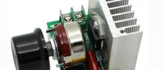
If there is no opportunity or desire to purchase a factory-type regulator, then you can assemble it yourself. Although regulators of the "tda1085" type have proven themselves very well. To do this, you need to familiarize yourself with the theory in detail and start practicing. Triac circuits are very popular, in particular the speed controller of a 220V asynchronous motor (diagram 5). It's not difficult to make. It is assembled using a VT138 triac, which is well suited for these purposes.
Scheme 5 - Simple speed controller on a triac.
This regulator can also be used to adjust the speed of a 12-volt DC motor, as it is quite simple and universal. The speed is regulated by changing the parameters P1, which determines the phase of the incoming signal, which opens the transition of the triac.
The operating principle is simple. When the engine starts, it slows down, the inductance changes downward and contributes to an increase in U in the “R2—>P1—>C2” circuit. When C2 is discharged, the triac opens for some time.
There is another scheme. It works a little differently: by providing a reverse type of energy flow, which is optimally beneficial. The circuit includes a fairly powerful thyristor.
Scheme 6 - Design of a thyristor regulator.
The circuit consists of a control signal generator, an amplifier, a thyristor and a circuit section that functions as a rotor rotation stabilizer.
The most universal circuit is a regulator based on a triac and dinistor (scheme 7). It is able to smoothly reduce the shaft rotation speed, reverse the motor (change the direction of rotation) and reduce the starting current.
The principle of operation of the circuit:
- C1 is charged until U breakdown of dinistor D1 through R2.
- When D1 breaks, it opens the junction of triac D2, which is responsible for controlling the load.
The load voltage is directly proportional to the frequency component when D2 opens, which depends on R2. The circuit is used in vacuum cleaners. It contains universal electronic control, as well as the ability to easily connect 380 V power. All parts should be placed on a printed circuit board made using laser-iron technology (LUT). You can find out more about this board manufacturing technology on the Internet.
Thus, when choosing an electric motor speed controller, you can buy a factory one or make it yourself. Making a homemade regulator is quite simple, since if you understand the principle of operation of the device, you can easily assemble it. In addition, you should follow safety rules when installing parts and when working with electricity.
Smooth engine operation, without jerks or power surges, is the key to its durability. To control these indicators, an electric motor speed controller is used for 220V, 12V and 24V; all of these frequencies can be made with your own hands or you can buy a ready-made unit.
voltage regulation
Just recently (10 years ago), there were a limited number of frequency controllers for motor speeds on the market, and they were quite expensive. The reason is that there were no cheap high-voltage power transistors and modules.
But developments in the solid-state field have allowed electronics to bring power IGBT-like to the market. modules result in the massive appearance on the market of inverter air conditioners, welding inverters, and frequency converters.
At the moment, this frequency conversion is the main method of regulating power, productivity, speed of all devices and the drive of mechanisms in which an electric motor is used.
However, frequency converters are designed to control three-phase single-phase.
Motors can be controlled by electric motors:
- specialized three-phase inverters
- single-phase inverters with the exception of the capacitor
Converters for single-phase motors
Currently, only one manufacturer announces serial production of a specialized inverter for capacitor motors - INVERTEK DRIVES.
This is the model for E2
Optidrive uses special algorithms to ensure stable engine starting and operation.
In this case, it is possible to adjust the frequency upward, but in a limited frequency range, this is prevented by a capacitor installed in the phase-shifting circuit of the winding, as its resistance directly depends on the frequency of the current:
Xc=1/2?fC
f - current frequency
C - capacitor capacity
The output stage uses a bridge with four output IGBT transistors:
Optidrive E2 allows you to control the motor without excluding the circuit, then the capacitor without changing the design of the motor - in some models this is quite difficult to do.
specialized Advantages of frequency converter:
- intelligent control stable
- engine stable engine operation
- huge modern capabilities of the inverter:
- the ability to control the operation of the maintenance engine for certain characteristics (water pressure, air flow, speed under changing load)
- numerous protections (motor and device itself)
- sensor inputs for (digital and analogue)
- various outputs
- communication interface (for control, monitoring)
- preset PID
- speed controller
Disadvantages of using a single-phase inverter:
- frequency limited control
- high price
Use of three-phase emergency conditions for motors
A standard frequency converter has a three-phase voltage output. When connecting a single-phase motor to it, remove the capacitor from it and connect it according to the diagram below:
Geometric arrangement of the windings relative to each other in the stator of an asynchronous motor Phase 90°:
is a three-phase voltage shift of -120°, the consequence of this is that the magnetic field will not be pulsating, but circular and its level will be less than with a power supply with a shift of 90°.
In some capacitor motors, the additional winding is made thinner and the wire has a higher resistance.
operation Without a capacitor this will lead to:
- stronger heating of the winding (service life is possible, short circuits and interturn short circuits are reduced)
- different current in Many
The windings of the inverter have protection against current asymmetry in the windings, if it is impossible to disable this function, the operation of the device according to this circuit will be impossible
more:
- Advantages: low cost compared to specialized inverters
- the choice is huge in terms of power and manufacturers
- wider frequency regulation range
- all the advantages of the inverter (inputs/intelligent, outputs, operating algorithms, communication interfaces)
method Disadvantages:
- the need for preliminary selection of the inverter and motor for joint operation
- pulsating and reduced torque
- increased heating
- no guarantee when leaving three-phase, because Inverters are not designed to work with single-phase Source
Working with the stator
When repairing and rewinding an electric motor, first of all, a diagram of the location and connection of the motor windings is drawn up. In the case of a three-phase motor, a coil diagram is carefully drawn up for each phase. They are usually wound with one wire. Only when the winding connection diagram is well studied and correctly drawn up can they be disassembled and removed. For convenience, we mark the windings with different colors and take photographs. We also check whether everything is clear in the photographs and diagrams.
Before rewinding the stator of the electric motor, we make a template according to its size. The width is equal to the size between the grooves in which the coil will be placed. To insulate the stator from the winding, we insert cardboard or special plastic plates into the grooves. To place the coil in the grooves, use a wooden or plastic spatula - a tamper.
When one coil has been wound, do not bite off the wire, place the coil in the grooves and continue winding it onto the template. We wind all the coils of the same phase using a solid wire, without cutting it. First of all, we rewind all the turns of one phase and lay them out one by one. In a similar way we wind and lay the coils for other phases. The upper part of the winding in the stator slots above the turns is covered with plates made of the same insulation material that is used in the stator slots.
Popular models of speed controllers for single-phase motors
Among the variety of devices that perform the function of controlling an electric motor, there are two main types of speed controller models. These are electronic thyristor single-phase speed controllers that operate by smoothly changing the supply voltage. The second type of speed controller models is a transformer single-phase speed controller. Its work is to change the position of a three-stage cam switch, which changes the switching combination of the windings.
Frequency control for speed control of asynchronous electric motors is a technical standard nowadays. The use of a frequency regulator has replaced many control methods. Symmetrical and asymmetrical voltage control and the use of additional resistances, changing the number of pole pairs are a thing of the past.
Frequency generator, frequency converter 220 - 380 motor speed controller
Watch this video on YouTube
Making homemade relays
Making a homemade speed controller for a 12 V electric motor will not be difficult. For this work you will need the following:
- Wirewound resistors.
- Switch for several positions.
- Control unit and relay.
The use of wirewound resistors allows you to change the supply voltage and, accordingly, the engine speed. Such a regulator provides stepwise acceleration of the engine, has a simple design and can be made even by novice radio amateurs. Such simple homemade step regulators can be used with asynchronous and contact motors.
Operating principle of a homemade converter:
- Power from the network is sent to the capacitor.
- The used capacitor is fully charged.
- The load is transferred to the resistor and the bottom cable.
- The thyristor electrode connected to the positive terminal on the capacitor receives the load.
- A voltage charge is transmitted.
- The discovery of the second semiconductor occurs.
- The thyristor passes the load received from the capacitor.
- The capacitor is completely discharged, after which the half-cycle is repeated.
In the past, the most popular were mechanical regulators based on a variator or gear drive. However, they were not very reliable and often failed.
Homemade electronic regulators have proven themselves to be the best. They use the principle of changing step or smooth voltage, are durable, reliable, have compact dimensions and provide the ability to fine-tune the operation of the drive.
The additional use of triacs and similar devices in electronic regulator circuits allows for a smooth change in voltage power; accordingly, the electric motor will correctly gain speed, gradually reaching its maximum power.
Frequency converter: types, principle of operation, connection diagrams
The frequency converter allows its owner to reduce energy consumption and automate processes in equipment and production management.
The main components of the frequency converter: rectifier, capacitor, IGBT transistors assembled into an output stage.
Thanks to the ability to control the parameters of the output frequency and voltage, a good energy-saving effect is achieved. Energy saving is expressed in the following:
- The engine maintains a constant current torque of the shaft. This is due to the interaction of the output frequency of the inverter converter with the engine speed and, accordingly, the dependence of voltage and torque on the engine shaft. This means that the converter makes it possible to automatically regulate the output voltage when it detects a voltage value that exceeds the norm with a certain operating frequency necessary to maintain the required torque. All inverter converters with vector control have the function of maintaining constant torque on the shaft.
- The frequency converter is used to regulate the operation of pumping units (see page). When receiving a signal from a pressure sensor, the frequency generator reduces the performance of the pumping unit. As the engine speed decreases, the output voltage consumption decreases. Thus, standard water consumption by a pump requires 50Hz industrial frequency and 400V voltage. Using the power formula, you can calculate the ratio of power consumption.
By reducing the frequency to 40Hz, the voltage is reduced to 250V, which means that the number of pump revolutions is reduced and energy consumption is reduced by 2.56 times.
Rice. No. 6. Using a Speedrive frequency converter to regulate pumping units using the CKEA MULTI 35 system.
To increase the energy efficiency of using a frequency converter in electric motor control, you must do the following:
- The frequency converter must match the parameters of the electric motor.
- The frequency generator is selected in accordance with the type of working equipment for which it is intended. Thus, the frequency converter for pumps operates in accordance with the parameters included in the program to control the operation of the pump.
- Precise settings of control parameters in manual and automatic mode.
- The frequency converter allows the use of energy saving mode.
- Vector control mode allows automatic adjustment of engine control.
Using Pulse Width Modulation
To control and adjust the speed of rotation of an asynchronous type electric motor, you can use a pulse regulator-voltage stabilizer (inverter). It will act as a power source. It is based on the use of a TL494 pulse PWM regulator. The supply voltage of the electric motor, coming out after the PWM controller, will change in accordance with the change in rotation speed. Using this method, a greater economic effect is achieved, the device is quite simple and at the same time increases the efficiency of regulation.
The figure above shows a diagram of using a PWM controller for a three-phase asynchronous motor connected through a capacitor to a single-phase network.
This method, despite its effectiveness, has two significant drawbacks:
- impossibility of reverse motor control without the use of additional switching devices;
- frequency converters used in the regulator are high cost and are produced by a limited number of manufacturers.
Features of speed control
It is important to know that each motor, when rotating, consumes not only active, but also reactive power. In this case, the reactive power level will be higher, which is due to the nature of the load
In this case, the task of designing devices for regulating the rotation speed of commutator motors is to reduce the difference between active and reactive powers. Therefore, such converters will be quite complex, and it is not easy to make them yourself.
You can construct only some semblance of a regulator with your own hands, but there is no point in talking about saving power. What is power? In electrical terms, it is the current drawn multiplied by the voltage. The result will give a certain value that includes active and reactive components. To isolate only the active one, that is, to reduce losses to zero, it is necessary to change the nature of the load to active. Only semiconductor resistors have these characteristics.
Therefore, it is necessary to replace the inductance with a resistor, but this is impossible, because the motor will turn into something else and obviously will not set anything in motion. The goal of lossless regulation is to maintain torque, not power: it will still change. Only a converter can cope with such a task, which will control the speed by changing the duration of the opening pulse of thyristors or power transistors.
Types of adjustment
There are quite a few options for adjusting the speed. Here are the main ones:
- Power supply with adjustable output voltage.
- Factory adjustment devices that initially come with the electric motor.
- Push-button regulators and standard regulators that simply limit the voltage.
These types of adjustments are bad because as the voltage decreases or increases, the power also drops. In some power tools this is acceptable, but, as practice shows, in most cases this is unacceptable due to a strong drop in power and, accordingly, efficiency.
The most acceptable option would be a regulator based on a triac or thyristor. Not only does such a regulator not reduce power when the voltage decreases, it also allows for smoother starting and speed control. In addition, such a scheme can be made with your own hands. Below is a picture of the speed control with power maintenance. The circuit is assembled on the basis of a BTA 41,800 V triac.
All ratings of electrical elements are indicated in the diagram. This is the circuit after assembly, it works quite stably and provides smooth adjustment of the brushed motor. When the output voltage decreases, the power does not decrease, which is a significant plus.
If desired, you can assemble the speed controller of a 220 V brushed motor with your own hands. This circuit is assembled on the basis of a VTA26-600 triac, which must first be installed on a radiator, since this element gets quite hot under load.
The diagram looks like this.
It can successfully cope with the adjustment of power tools such as a drill, grinder, circular saw, and jigsaw. If desired, you can use the circuit as a power regulator for heating elements, heaters, and as a dimmer. The disadvantages include the impossibility of adjusting the power of devices powered by direct current.
https://youtube.com/watch?v=vVeR4jVfTIg
Difficulties in PWM speed control of a DC motor
PWM is a popular method for regulating analog voltage in various circuits. When using this control method, the user may experience unpredictable motor behavior. For example, the shaft may begin to rotate in the opposite direction. This occurs at low capacitive loads. In commutator motors, the armature windings are constantly switched during operation. When the regulator is connected, the power switches off and on at a certain frequency. Additional commutation in combination with a commutator can lead to problems with engine operation. Therefore, control devices with PWM motor control must be carefully thought out and designed.
Also, the cause of unstable operation of the electric motor may be the fact that the current strength influences the rotor rotation speed, which depends on the level of applied voltage. Problems may arise when operating motors at low speed relative to the rated speed.
For example, the user has a motor that, at rated voltage, rotates the rotor at a speed of 10 rpm. To reduce the speed to 1 rps, it is not enough to simply reduce the voltage to 1V. It is difficult to select the appropriate value of the supplied voltage, and even if the user succeeds, with a slight change in operating conditions, the speed will change again.
The solution to the problem is to use an automatic control system or briefly turn on the electric motor at full power. The rotor will move jerkily, but with the correct frequency and duration of the applied pulses, the rotation can be made more stable. Thus, they achieve stable movement of the electric motor shaft at any speed that will not change depending on the load.
Single-phase frequency converter
The compact frequency conversion device is used to control single-phase electric motors for household equipment. Most frequency converters have the following design capabilities:
- Most models use the latest vector control technologies in their design.
- They provide improved torque for single-phase motors.
- Energy saving is set to automatic mode.
- Some models of frequency converters use a removable control panel.
- Built-in PLC controller (it is indispensable for creating data collection and transmission devices, for creating telemetry systems, and integrates devices with various protocols and communication interfaces into a common network).
- Built-in PID controller (monitors and regulates temperature, pressure and technological processes).
- The output voltage is adjusted automatically.
Fig. No. 7. Modern Optidrive converter with basic functional features.
The frequency converter does not serve for double voltage conversion; due to the presence of a PWM regulator in the design, it can increase the voltage value by no more than 10%.
The main task of a single-phase frequency converter is to provide power to both single- and three-phase electric motors. In this case, the motor current will correspond to the connection parameters from a three-phase network and remain constant
Frequency controller structure
Currently, two main topologies of multilevel frequency converters have been developed in detail and are widely used. These are cascade and converters based on multi-level frequency voltage inverters.
Rice. No. 3 Block diagram of a high-voltage multilevel frequency converter, built on the basis of air- or water-cooled IGBT transistors.
The device includes a multi-winding transformer. Features of the circuit include the presence of power cells with a serial connection, due to which a total high voltage is obtained at the output of the device. Such a circuit serves to obtain an output voltage shape that is almost close to an ideal sine wave. The presence of cells that are shunted at the time of malfunction determines the high reliability of the circuit.
As a continuation of the previous circuit, we will consider a converter circuit based on a transformer multilevel voltage inverter with pulse width modulation using IGBT modules. The device is characterized by a fixed PWM frequency of 3 kHz. The structure of the device includes a protection system using a microprocessor.
Rice. 4 Block diagram of the converter.
The diagram shows that all blocks are functionally interconnected. The diagram shows how a frequency regulator works for an asynchronous motor, its structure and principle of operation.
The first block contains an input transformer; the block transmits electricity from a three-phase high-voltage power source. From the multi-level transformer, the reduced voltage is distributed into the inverter cabinet to the multi-level inverter.
The inverter cabinet includes a multi-level three-phase inverter consisting of converter cells. Each contains a six-pulse filter for rectifying the DC link and a bridge voltage inverter based on IGBT transistors. According to the circuit, the input alternating current is rectified, which, thanks to the inverter, is changed into alternating current with adjustable frequency and voltage.
The control protection cabinet contains a microprocessor unit with multifunctional capabilities and a power supply system from the converter TSN, a converter input device and primary sensors indicating the operating modes of the converter.
The microprocessor is used to generate inverter control signals depending on the designated operating algorithm. It is used to process information collected from voltage and current sensors. The microprocessor generates signals to control protections and emergency control buttons, and adjusts the control algorithm.
Fiber optic cable is used to transmit information and communication. For uninterrupted operation there is an independent built-in power supply. Parameter editing is performed using the remote control.
For reliable shutdown and safe performance of various types of work, the converter is equipped with a linear disconnector.
Rice. No. 5 Generalized diagram of the converter cell
Controlled alternating voltage sources form a voltage phase to perform their series connection. The output circuit of the supply network of an asynchronous motor occurs according to the “Star” winding connection diagram. The voltage in a three-phase inverter is distributed according to the circuit.
Rice. No. 6 Voltage distribution diagram in the inverter into three phases.
System design
The commutator type motor consists mainly of a rotor, a stator, as well as brushes and a tachogenerator.
- The rotor is part of the rotation, the stator is an external type of magnet.
- Brushes, which are made of graphite, are the main part of the sliding contact, through which voltage is applied to the rotating armature.
- A tachogenerator is a device that monitors the rotation characteristics of a device. If there is a violation in the regularity of the rotation process, then it adjusts the voltage level entering the engine, thereby making it smoother and slower.
- Stator. Such a part may include not one magnet, but, for example, two pairs of poles. At the same time, instead of static magnets, there will be coils of electromagnets. Such a device is capable of performing work both from direct current and alternating current.
Voltage regulation
Speed regulation in this way is associated with a change in the so-called sliding motor - the difference between the rotation speed of the magnetic field created by the stationary stator of the motor and its moving rotor:
S=(n1-n2)/n2
n1 - magnetic rotation speed
n2 — rotor rotation fields
In this case, sliding energy is necessarily released - which is why the windings of the motor heat up more.
This method has a small regulation range, approximately 2:1, and can only be carried out downwards - that is, by reducing the supply voltage.
In order to control the speed control voltage in this way, it is necessary to install motors with increased power.
But despite this, this method is used quite often in low-power engines with a fan load.
In practice, various Autotransformer circuits are used for this.
regulators voltage regulation
An autotransformer is an ordinary transformer, but with one winding and with taps from the Pri part. There is no galvanic isolation from this turns, but the network is not needed in this case, so savings are achieved due to the absence of a secondary winding.
The diagram shows the autotransformer T1, the switch SW1, which receives different voltages from the taps, and the motor M1.
Adjustment is usually obtained in a stepwise manner, no more than 5 steps of regulation are used.
Advantages of this scheme:
- undistorted pure output waveform (sinusoid voltage)
- good overload capacity Disadvantages
transformer:
- large mass and dimensions of the transformer (power depends on the load motor)
- all the disadvantages of regulation inherent in voltage
Thyristor speed controller for this
In the motor circuit, switches are used - two switched on, thyristors are counter-parallel (the voltage is alternating, each thyristor therefore transmits its half-wave or) voltage triac.
The control circuit regulates the opening and closing moment of the thyristors relative to the phase one through the zero transition; accordingly, a piece is “cut off” either at the beginning, less often at the end of the voltage wave.
Thus, the root mean square value of the voltage changes.
This circuit is quite widely used for active load control - incandescent lamps and all kinds of heating devices (so-called dimmers).
Another way of regulation is to skip half-cycles of the wave at a voltage frequency of 50 Hz for the engine, this will be noticeable - noise and jerking at For.
When controlling motors, regulators are modified due to the inductive characteristics of the load:
- install protective LRCs for the power switch protection circuit (capacitors, chokes, resistors)
- add a capacitor at the output to shape the voltage wave correction
- limit the minimum regulation of voltage power - for a guaranteed start they use
- motor thyristors with a current several times higher than the electric motor current
Advantages of thyristor regulators:
- low cost
- low weight and dimensions
Flaws:
- Can be used for low power engines
- during operation there may be noise, crackling, jerking when
- motor using triacs, the motor receives DC voltage
- all the disadvantages of voltage regulation
It is worth noting that in most modern air conditioners of the highest and mid-level, the fan speed is regulated in this way.