The number of repetitions of any events or their occurrence in one timer unit is called frequency. This physical quantity is measured in hertz – Hz (Hz). It is denoted by the letters ν, f, F, and is the ratio of the number of repeating events to the period of time during which they occurred.
Rotation of planets around the Sun
When an object rotates around its center, we can talk about such a physical quantity as rotation frequency, the formula:
ν = N/t,
Where:
- N – number of revolutions around an axis or in a circle,
- t is the time during which they were completed.
In the SI system it is denoted as – s-1 (s-1) and is referred to as revolutions per second (rps). Other units of rotation are also used. When describing the rotation of planets around the Sun, they speak of revolutions in hours. Jupiter rotates once every 9.92 hours, while the Earth and Moon rotate every 24 hours.
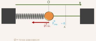
Linear speed
Each point on the circle moves at a certain speed. This speed is called linear. The direction of the linear velocity vector always coincides with the tangent to the circle.
For example, sparks from under a grinding machine move, repeating the direction of instantaneous speed.
Consider a point on a circle that makes one revolution, the time spent is the period T
. The path that a point travels is the circumference.
Torque
This term has several synonyms: torque, motor torque, torque, torque. All of them are used to denote one indicator, although from the point of view of physics these concepts are not always identical.
In order to unify terminology, standards have been developed that bring everything to a single system. Therefore, in technical documentation the phrase “torque” is always used. It is a vector physical quantity that is equal to the product of the vector values of force and radius. The radius vector is drawn from the axis of rotation to the point of applied force. From a physics perspective, the difference between torque and torque lies in the point at which the force is applied. In the first case it is an internal effort, in the second it is an external one. The value is measured in newton meters. However, in the electric motor power formula, torque is used as the main value.
It is calculated as
M = F × r, where:
M — torque, Nm;
F is the applied force, H;
r—radius, m.
To calculate the rated torque of the drive, use the formula
Mnom = 30Рnom ÷ pi × nnom, where:
Rnom - rated power of the electric motor, W;
nnom - nominal speed, min-1.
Accordingly, the formula for the rated power of the electric motor should look like this:
Pnom = Mnom * pi*nnom / 30.
Usually all characteristics are indicated in the specification. But it happens that you have to work with completely new installations, information about which is very difficult to find. To calculate the technical parameters of such devices, data from their analogs is taken. Also, only the nominal characteristics that are given in the specification are always known. Real data must be calculated independently.
Centripetal acceleration
When moving in a circle, the acceleration vector is always perpendicular to the velocity vector, directed towards the center of the circle.
Using the previous formulas, we can derive the following relationships
Points lying on the same straight line emanating from the center of the circle (for example, these could be points that lie on the spokes of a wheel) will have the same angular velocities, period and frequency. That is, they will rotate the same way, but with different linear speeds. The further a point is from the center, the faster it will move.
The law of addition of speeds is also valid for rotational motion. If the motion of a body or frame of reference is not uniform, then the law applies to instantaneous velocities. For example, the speed of a person walking along the edge of a rotating carousel is equal to the vector sum of the linear speed of rotation of the edge of the carousel and the speed of the person.
Rotation angle and period of revolution
Consider point A on an object rotating around its axis. When circulating over a certain period of time, it will change its position on the circle line by a certain angle. This is the rotation angle. It is measured in radians, because the unit is a segment of a circle equal to the radius. Another value for measuring the angle of rotation is a degree.
Current frequency
When, as a result of the rotation, point A returns to its original place, it means that it has completed a full rotation. If its movement is repeated n times, then we speak of a certain number of revolutions. Based on this, you can consider 1/2, 1/4 turn and so on. A striking practical example of this is the path that a cutter takes when milling a part fixed in the center of the machine spindle.
Attention! The rotation angle has a direction. It is negative when the rotation occurs clockwise and positive when it rotates counterclockwise.
If a body moves uniformly around a circle, we can talk about a constant angular velocity during movement, ω = const.
In this case, the following characteristics are used:
- period of revolution – T, this is the time required for a full revolution of a point in a circular motion;
- circulation frequency – ν, this is the total number of revolutions that a point makes along a circular path in a unit time interval.
Interesting. According to known data, Jupiter revolves around the Sun every 12 years. When the Earth makes almost 12 revolutions around the Sun during this time. The exact value of the round giant's orbital period is 11.86 Earth years.
Connection to Newton's second law
According to Newton's second law, the cause of any acceleration is force. If a moving body experiences centripetal acceleration, then the nature of the forces that cause this acceleration may be different. For example, if a body moves in a circle on a rope tied to it, then the acting force is the elastic force.
If a body lying on a disk rotates with the disk around its axis, then such a force is the friction force. If the force stops its action, then the body will continue to move in a straight line
Types of electric motors
Based on the power source, drives are divided into those powered by:
- Direct current.
- Alternating current.
According to the principle of operation, they, in turn, are divided into:
- Collector.
- Valve.
- Asynchronous.
- Synchronous.
Valve motors are not classified as a separate class, since their design is a variation of a commutator drive. Their design includes an electronic converter and a rotor position sensor. They are usually integrated together with a control board. Due to them, coordinated commutation of the armature occurs.
Synchronous and asynchronous motors operate exclusively on alternating current. The speed is controlled using sophisticated electronics. Asynchronous are divided into:
- Three-phase.
- Two-phase.
- Single-phase.
Theoretical formula for the power of a three-phase electric motor when connected in a star or delta
P = 3 * Uph * Iph * cos(alpha).
However, for linear values of voltage and current it looks like
P = 1.73 × Uph × Iph × cos(alpha).
This will be a real indicator of how much power the engine takes from the network.
Synchronous are divided into:
- Stepper.
- Hybrid.
- Inductor.
- Hysteretic.
- Reactive.
Stepper motors have permanent magnets in their design, so they are not classified as a separate category. The operation of the mechanisms is controlled using frequency converters. There are also universal motors that operate on direct and alternating current.
Movement along a cycloid*
In the reference frame associated with the wheel, the point rotates uniformly along a circle of radius R with a speed that changes only in direction. The centripetal acceleration of a point is directed radially towards the center of the circle.
Now let's move to a stationary system connected to the ground. The total acceleration of point A will remain the same both in magnitude and direction, since when moving from one inertial reference system to another, the acceleration does not change. From the point of view of a stationary observer, the trajectory of point A is no longer a circle, but a more complex curve (cycloid), along which the point moves unevenly.
Instantaneous speed is determined by the formula
Cyclic speed (reversal)
Mechanical Power Formula - Average and Instantaneous Power
A scalar quantity that measures the frequency of rotational motion is called cyclic speed. This is the angular frequency, which is not equal to the angular velocity vector itself, but to its magnitude. It is also called radial or circular frequency.
Cyclic rotation frequency is the number of body revolutions in 2*π seconds.
For AC electric motors, this frequency is asynchronous. Their rotor speed lags behind the rotation speed of the stator magnetic field. The value that determines this lag is called slip - S. During the sliding process, the shaft rotates because an electric current arises in the rotor. Slip is permissible up to a certain value, exceeding which leads to overheating of the asynchronous machine, and its windings may burn out.
The design of this type of motor differs from the design of DC machines, where a current-carrying frame rotates in the field of permanent magnets. The armature contained a large number of frames, and many electromagnets formed the basis of the stator. In three-phase AC machines the opposite is true.
When an asynchronous motor operates, the stator has a rotating magnetic field. It always depends on the parameters:
- mains frequency;
- number of pole pairs.
The rotation speed of the rotor is in direct relation to the speed of the stator magnetic field. The field is created by three windings, which are located at an angle of 120 degrees relative to each other.
Determining the speed
There are several ways to measure motor speed. The most reliable is to use a tachometer - a device designed specifically for this purpose. However, not every person has such a device, especially if he does not work with electric motors professionally. Therefore, there are several other options that allow you to cope with the task “by eye”.
The first involves removing one of the motor covers to reveal the winding coil. There may be several of the latter. The one that is more accessible and located in the visibility zone is selected. The main thing is to prevent the integrity of the device from being damaged during operation.
When the coil is revealed to the eye, you need to carefully examine it and try to compare the size with the stator ring. The latter is a stationary element of the electric motor, and the rotor, being inside it, rotates.
The second method is related to the windings inside the stator. The number of slots occupied by one section of a coil is calculated. The grooves are located on the core, their number indicates the number of pairs of poles. 3000 rpm will be if there are two pairs of poles, with four - 1500 rpm, with six - 1000.
The answer to the question of what the number of revolutions of an electric motor depends on is the following statement: the number of pole pairs, and this is an inversely proportional dependence.
On the body of any factory engine there is a metal tag on which all the characteristics are indicated. In practice, such a tag may be missing or erased, which slightly complicates the task of determining the number of revolutions.
Operating principle
If we explain the principle of operation of a frequency converter, then we can say that the use of this device allows you to effectively and efficiently control the operation of powerful asynchronous electric motors.
The equipment is a variable frequency drive (VFD), due to which the technical characteristics of machines and mechanisms have been improved. To change the speed of the motor shaft, it is necessary to adjust the amplitude of the voltage and frequency. The operating principle of the frequency converter is based on two methods:
Scalar control - allows adjustment according to a linear law, when the amplitude and frequency depend proportionally on each other. That is, a change in frequency affects the amplitude of the incoming voltage, which affects the torque and power factor of the mechanism
It is very important that the load torque on the motor shaft remains the same, and the ratio of voltage to output frequency remains unchanged. Vector regulation - allows you to maintain a constant load at any frequency changes. Provides more precise control and the drive responds more smoothly to changes in power output
It should be taken into account that the rotation torque is affected by the magnitude of the stator current, or more precisely, by the magnetic field that it creates.
Industrial voltage is supplied to a rectifier, which smoothes out the sinusoids, leaving a ripple in the signal. To eliminate them and smooth out the shape of the output voltage, capacitors with inductance are provided in the design.
To ensure smooth braking of rotation, an adjustable transistor with powerful resistance is built into the design. A frequency converter for an electric motor works on this principle.
Types of devices
Depending on the design features, the main types of frequency converters 220/380 are distinguished - induction and electronic. The first option includes asynchronous types of electric motors, the peculiarity of which is the use of a wound-rotor circuit.
But the electronic version can be used both in the operation of asynchronous engines and synchronous modifications. Motors are controlled in several fundamentally different ways:
Through scalar control, based on linear patterns. In this case, the proportional dependence of amplitude on frequency is taken into account. If the frequency changes, the amplitude of the input voltage will also change. As a result, torque, efficiency, and power levels are affected.
Setting the uniformity of the load torque is ensured by a constant ratio of the amplitude to the output frequency. The transforming device forms the specified equilibrium.
With the vector approach, the load torque is constant at any range of frequency changes. This allows for greater control accuracy. The flexibility of the electric drive's response to surges in the output load also increases. The frequency converter for an asynchronous motor provides constant control over the torque.
It is important to remember that the phase of the stator current, which changes under the influence of the magnetic field, is the current vector. It controls the torque
Thus, in this case, an amplitude or pulse width signal control system is used.
Voltage regulation
Speed control in this way is associated with a change in the so-called engine slip - the difference between the rotation speed of the magnetic field created by the stationary engine stator and its moving rotor:
n1—magnetic field rotation speed
n2—rotor rotation speed
In this case, sliding energy is necessarily released - which causes the motor windings to heat up more.
This method has a small control range, approximately 2:1, and can also only be carried out downwards - that is, by reducing the supply voltage.
When regulating speed in this way, it is necessary to install oversized motors.
But despite this, this method is used quite often for low-power motors with a fan load.
In practice, various regulator circuits are used for this.
Autotransformer voltage regulation
An autotransformer is an ordinary transformer, but with one winding and taps from some of the turns. In this case, there is no galvanic isolation from the network, but in this case it is not needed, so savings are achieved due to the absence of a secondary winding.
The diagram shows autotransformer T1, switch SW1, which receives taps with different voltages, and motor M1.
The adjustment is done in steps; usually no more than 5 steps of regulation are used.
Advantages of this scheme:
- undistorted output voltage waveform (pure sine wave)
- good overload capacity of the transformer
Flaws:
- large mass and dimensions of the transformer (depending on the power of the load motor)
- all the disadvantages inherent in voltage regulation
Thyristor engine speed controller
This circuit uses keys - two thyristors connected back-to-back (the voltage is alternating, so each thyristor passes its own half-wave of voltage) or a triac.
The control circuit regulates the moment of opening and closing of the thyristors relative to the phase transition through zero; accordingly, a piece is “cut off” at the beginning or, less often, at the end of the voltage wave.
This changes the rms voltage value.
This circuit is quite widely used to regulate active loads - incandescent lamps and all kinds of heating devices (so-called dimmers).
Another method of regulation is to skip half-cycles of the voltage wave, but at a network frequency of 50 Hz this will be noticeable for the motor - noise and jerking during operation.
To control motors, regulators are modified due to the characteristics of the inductive load:
- install protective LRC circuits to protect the power switch (capacitors, resistors, chokes)
- add a capacitor at the output to adjust the voltage waveform
- limit the minimum voltage regulation power - for guaranteed engine start
- use thyristors with a current several times higher than the electric motor current
Advantages of thyristor regulators:
Flaws:
- can be used for low power engines
- During operation, noise, crackling, and jerking of the engine may occur.
- when using triacs, a constant voltage is applied to the motor
- all the disadvantages of voltage regulation
It is worth noting that in most modern mid- and high-level air conditioners, the fan speed is adjusted in this way.
Transistor voltage regulator
As the manufacturer himself calls it, an electronic autotransformer or PWM regulator.
The voltage is changed using the PWM (pulse width modulation) principle, and transistors are used in the output stage - field-effect or bipolar with insulated gate (IGBT).
The output transistors are switched at a high frequency (about 50 kHz); if you change the width of the pulses and pauses between them, the resulting voltage at the load will also change. The shorter the pulse and the longer the pause between them, the lower the resulting voltage and power input.
For a motor, at a frequency of several tens of kHz, a change in the pulse width is equivalent to a change in voltage.
The output stage is the same as that of a frequency converter, only for one phase there is a diode rectifier and two transistors instead of six, and the control circuit changes the output voltage.
Advantages of an electronic autotransformer:
- Small dimensions and weight of the device
- Low cost
- Clean, undistorted current output waveform
- No hum at low speeds
- 0-10 Volt signal control
Weak sides:
- The distance from the device to the engine is no more than 5 meters (this disadvantage is eliminated when using a remote controller)
- All the disadvantages of voltage regulation
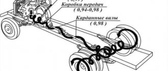
How to calculate gear ratio
The gear and wheel have a different number of teeth with the same module and proportional diameters. The gear ratio shows how many revolutions the driving part will make to turn the driven part a full circle. Gears have a rigid connection. The transmitted number of revolutions in them does not change. This negatively affects the operation of the unit under conditions of overload and dust. The tooth cannot slip like a belt on a pulley and breaks.
Calculation without resistance
When calculating the gear ratio, the number of teeth on each part or their radii are used.
u12 = ± Z2/Z1 and u21 = ± Z1/Z2,
Where u12 is the gear and wheel gear ratio;
Z2 and Z1 are the number of teeth of the driven wheel and drive gear, respectively.
The “+” sign is placed if the direction of rotation does not change. This applies to planetary gearboxes and gears with teeth cut along the inner diameter of the wheel. If there are parasites - intermediate parts located between the drive gear and the ring gear, the direction of rotation changes, as with an external connection. In these cases, “–” is placed in the formula.
When two parts are externally connected by means of a parasite located between them, the gear ratio is calculated as the ratio of the number of teeth of the wheel and gear with the “+” sign. The parasite does not participate in the calculations, it only changes the direction, and accordingly the sign in front of the formula.
Typically, the clockwise direction of movement is considered positive. The sign plays a big role in the calculations of multi-stage gearboxes. The gear ratio of each gear is determined separately according to the order in which they are located in the kinematic chain. The sign immediately shows the direction of rotation of the output shaft and the working unit, without additional diagramming.
Calculation of the gear ratio of a gearbox with several gears - multi-stage, is defined as the product of gear ratios and is calculated by the formula:
u16 = u12×u23×u45×u56 = z2/z1×z3/z2×z5/z4×z6/z5 = z3/z1×z6/z4
The gearing is rigid. The parts cannot slide relative to each other, as in a belt drive, and change the ratio of the number of rotations. Therefore, the output speed does not change and does not depend on overload. The calculation of the angular speed and the number of revolutions turns out to be correct.
Gear efficiency
To actually calculate the gear ratio, additional factors must be taken into account. The formula is valid for angular velocity; as for the moment of force and power, they are much less in a real gearbox. Their value is reduced by the resistance of transmission moments:
- friction of contacting surfaces;
- bending and twisting of parts under the influence of force and resistance to deformation;
- losses on keys and splines;
- friction in bearings.
Each type of connection, bearing and assembly has its own correction factors. They are included in the formula. Designers do not make calculations for the bending of each key and bearing. The directory contains all the necessary coefficients. If necessary, they can be calculated. The formulas are no different from simplicity. They use elements of higher mathematics. The calculations are based on the ability and properties of chromium-nickel steels, their ductility, tensile strength, bending, fracture and other parameters, including the dimensions of the part.
As for bearings, the technical reference book from which they are selected contains all the data for calculating their operating condition.
When calculating power, the main indicator of gearing is the contact patch, it is indicated as a percentage and its size is of great importance. Only drawn teeth can have an ideal shape and touch throughout the entire involute. In practice, they are manufactured with an error of several hundredths of a mm. When the unit operates under load, spots appear on the involute in places where the parts interact with each other. The more area on the tooth surface they occupy, the better the force is transmitted during rotation.
All coefficients are combined together and the result is the gearbox efficiency value. The efficiency is expressed as a percentage. It is determined by the ratio of power on the input and output shafts. The more gears, connections and bearings, the less efficiency.
What does the converter provide?
The need to use an electric motor speed controller in the case of asynchronous models is as follows:
Significant savings in electrical energy are achieved. Since not all equipment requires high rotation speeds of the motor shaft, it makes sense to reduce it by a quarter.
Reliable protection of all mechanisms is provided. The frequency converter allows you to control not only temperature, but also pressure and other system parameters. This fact is especially important if a pump is driven by a motor.
A soft start is performed. Thanks to the regulator, the need to use additional electronic devices is eliminated. The frequency converter is easy to set up and get the desired effect.
Maintenance costs are reduced because the regulator minimizes the risk of damage to the drive and other mechanisms.
Thus, electric motors with speed control turn out to be reliable devices with a wide range of applications.
It is important to remember that the operation of any equipment based on an electric motor will only be correct and safe when the rotation speed parameter is adequate to the conditions of use.