To understand what a single-stage gearbox is, you must first determine what the device is in its classic version. A gearbox is a mechanism consisting of clutch gears that transmit working motion to each other. Due to their simplicity, high efficiency and low cost, gearboxes are widely used in mechanical engineering to create a variety of interconnected mechanisms.
The gearbox housing contains worm or gear drives, which are mounted by welding or other immobilizing methods on shafts or axles. The former are pressed into bearings, which are located in holes specially made for them in the housing. Such a transmission can be mounted directly on a unit that produces mechanical movement, but installed in a separate housing (gearbox) it has a number of advantages. In particular these are:
- guarantee of high accuracy of mechanism assembly;
- increased efficiency;
- better lubrication of gearbox parts;
- reduced wear;
- increased level of protection against the entry of harmful saws and dirt.
It consists of a welded steel or cast iron body. It houses shafts, axles, gears, worm gears, bearings and other elements. Some gearboxes contain special devices that provide lubrication of gearbox elements. For example, it may be equipped with an oil pump or a device that provides cooling for this unit (a coil with coolant is often mounted in a worm gearbox).
Gearboxes are different. At the same time, they differ not only in types, but also in individual characteristics, so gearboxes are designed for specific equipment or unit, depending on the need, gear ratio and torque that needs to be transmitted to the receiving device.
Main types of gearboxes
- By type of transfer connection to:
- toothed;
- worm;
- combined.
- Depending on the shape of the gears on;
- cylindrical;
- conical and others.
- According to the location of the shafts in space on:
- vertical;
- horizontal.
- Depending on the characteristics of the kinematic system that underlies a particular mechanism on:
- expanded;
- with double stage, etc.
- By the number of steps:
- single stage;
- two-stage.
Recommendations for selection
How to choose a gearbox instead of a broken one, for existing equipment and when creating mechanisms yourself. The main thing is the power on the output shaft. It is calculated based on engine speed by gear ratio.
You should pay attention to the location of the shafts; in cylindrical models it can be in one direction.
Fastening is carried out using a flange directly to the motor shaft and is installed on the platform using holes in the sole.
The marking indicates the center-to-center distance between the shafts. This size has a design significance when installing the unit and connecting it to the engine and the shaft of the working mechanism.
You should look at which pair is the first in the gearbox, its gear ratio, gearing. The choice of gearbox also includes the location of the shafts in space. They can be located at right angles and be in different planes. The type of bearings is indicated in the technical documentation. There is also a table of service life of different components.
When designing a machine, the selection of a worm gearbox is carried out based on power and gearing location. With lower engagement, the pair is well lubricated, does not require additional cooling and can operate for a long time
You should pay attention to the operating mode. The node is not always able to work for several hours continuously
The worm joint overheats quickly.
Single stage helical gearboxes
This type of gearbox differs from others in the position of the shafts in the housing and the number of stages. Single-stage helical gearboxes can be vertical or horizontal. The gears of these devices can have oblique and straight teeth, as well as chevron teeth. The housings are made from steel by welding or from cast iron by casting. Shafts are often mounted in plain or rolling bearings. The former are often installed in heavy gearboxes.
The composition and layout capabilities of a single-stage gearbox are limited. The main feature that distinguishes them from each other is the location of the shafts and axes in space. Moreover, the gear ratio of these units ranges from 1.6 to 6.3. The inclination angle of gears made using helical gears ranges from 8 to 200 degrees.
The maximum gear ratio that the unit can provide is 12.5, but gearboxes with maximum gear ratios are rarely used. Often those that have a gear ratio not exceeding 6 are used.
Which gearbox arrangement should I choose - vertical or horizontal? It all depends on the need for convenience in the overall layout of this transmission device. In particular, it matters how the unit that produces the mechanical movement is located, its working shaft, etc.
To create such a device, you first need to make its circuit. We propose to study one of the options for a single-stage gearbox with horizontal axes.
Defects in the gearbox
How to determine the rear axle gearbox of a VAZ
Increased play in the RZM can be formed due to wear of the differential pinion pin - if you grab the driveshaft and rotate it clockwise and counterclockwise, this play can be felt. Also, increased clearance can be formed due to wear of the splines inside the differential housing itself.
If the gaps in the main pair of gearboxes are not adjusted, a characteristic noise occurs when the car moves:
- when the load increases (sharp acceleration), a characteristic howl is heard in the bridge;
- When I let off the gas the noise goes away.
The engine can hum in a different way, but the characteristic feature described above can most often be heard on VAZ classic cars. Worn teeth of the main pair are clearly visible on the planetary gear - they become rounded, and they often show traces of rust.
Operating principle of a single-stage gearbox
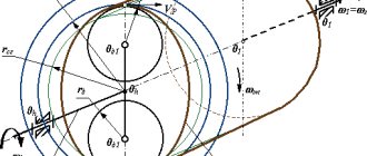
It's simple enough to understand. In such a mechanism, through a smaller sprocket located on one shaft to a larger one installed on another shaft, rotational motion is transmitted through the teeth. The effect of reducing the number of revolutions per minute is achieved due to the difference in the diameter of the sprockets. The length of the circle that the first one outlines during movement is significantly less than the one that the second one outlines, so the large asterisk rotates more slowly.
In this case, reverse-acting devices are created that do not reduce the number of revolutions per unit of time, but rather increase them.
This type of gearbox is the simplest. It differs from others in that motion is transmitted through one link, and not through several, while the incoming and outgoing rotations have opposite directions.
Read also: How an intercom circuit works
Torque can also be transmitted using a worm mechanism, but the gear ratio is affected by the diameter of the “worm”.
Design specifics of the rear axle gearbox
Wheels with meshing teeth that transmit torque to the driven shafts from the drive shaft are called gears. Due to the fact that the shafts are located at different angles, the teeth of the wheels are made of a special shape - this is the so-called. bevel gears.
Thanks for subscribing!
The cone shape, in addition to its main purpose of transmitting torque, also provides a low noise level, which is an advantage in terms of ease of operation of a passenger car.
The drive wheel must be of a different size than the driven ones - only in this case will a reduction in gear be ensured. If this requirement is met, several full rotations of the driven shaft will correspond to one full revolution of the driving shaft - in other words, there is a decrease (reduction) in the rotation speed. There are a number of vehicles (all-terrain vehicles, for example), where a serious reduction in rotation speed is applied in the gearbox - thus ensuring a very low pace of movement so as not to get bogged down.
Where and for what are single-stage horizontal gearboxes used?
They find their use:
- where constant or variable load, reversible and one direction is required;
- to ensure continuous work or with short breaks;
- to ensure rotation of the shafts in different directions.
They cannot or are dangerous to use if the shaft rotation speed exceeds 1800 revolutions per minute, as well as when the air dust content is higher than 10 mg per cubic meter. meter and atmosphere of the first and second types in accordance with GOST 15150-69.
Types of cases
The most common cases are made of high-strength cast iron, steel or metal alloys with reduced weight. They are mass-produced by casting in standard sizes. Steel and cast iron housings are characterized by increased strength. But if it is necessary to significantly reduce the weight of the mechanism, then aircraft aluminum can be used.
In case of single production or the need to manufacture devices in non-standard dimensions, the housings are manufactured by welding. This allows you to implement the required engineering ideas.
The cases are equipped with places for reliable fixation in the “la” or “ears” type. They help secure the device in accordance with the designed diagram. Seals must be provided at the outlet of the outer shafts. Their task is to prevent lubricant (oil) from leaking out. If necessary, there are injectors on the outside; they reduce the pressure generated inside the protective housing.
Design Process of Single Stage Helical Gearbox
Before starting to manufacture this device, a design calculation is made:
- selection of materials;
- selection of the maximum permissible rolling voltage;
- calculation of net useful shaft torsion.
As part of the work, the preliminary design of the gearbox is prepared.
The calculation of the shaft dimensions of this device is carried out in 2 stages:
- approximate calculation of the number of revolutions of pure torsion;
- accurate calculation of strength indicators of bending and torsion stress.
For the production of such units, it is recommended to use heat-treated alloy steel. The calculation of shafts when drawing up a project is carried out depending on the torsional stress, stress concentration, and its cycles. If you plan to install high-speed shafts, then smaller values are taken into account for the calculation, while low-speed shafts - larger ones.
At the final design stage, an assembly drawing of this device is created. It includes all previously developed drawings of each of the gearbox elements separately. In this case, a drawing of the finished device is created, in longitudinal and transverse sections.
To achieve balance and coaxiality in the arrangement of the various elements of this device, kinematic diagrams of single-stage gearboxes are being developed. They are images in different sections of the body and parts that make up the gearbox, reflecting their relative position, proportions, mating points, etc.
The layout of a single-stage gearbox can be different. It may have additional elements that significantly improve its performance. For example, an oil pump that provides forced lubrication in places where liquid does not enter when the sprocket flywheel rotates or in a worm-type gearbox.
You can create such a device yourself, but to do this you will need to purchase the necessary spare parts. An important element of the gearbox, which affects its characteristics, is the housing and the size of the sprockets, the diameter of the worm mechanism. For a person who does not have experience in this matter, patience and diligence will be required, but it is still possible to achieve the desired goal - to create a gearbox with the necessary parameters.
Assembling the device in this matter is the easiest job, and the most important and difficult is the design and selection of the necessary elements, spare parts and parts.
A helical gearbox is a mechanical device designed to reduce rotation speed and increase torque on the output shaft. It is used in electric, pneumatic and hydraulic drives of industrial equipment for various purposes. It is considered one of the most common types of gearboxes, characterized by high efficiency and simplicity of gear design.
What to do if the gearbox is noisy: advice from car owners
- When it howls under load. “Have you noticed that the gearbox is humming? All you can do in this case is tighten the shank nut. For more complex manipulations, you should contact a car service. But finding an experienced master is also not easy. The young specialist will at most disassemble and reassemble the mechanism. At the same time, they will also intimidate you that everything is really bad so that they can charge more for repairs. On my car, a hum appears when I press on the gas. But as soon as the load becomes less, there are no extraneous sounds. This indicates that a new master pair should be installed. Of course, nothing good, but it will have to be repaired.”
- It's expensive to change, but necessary.
“It is useless to make repairs when the main steam is humming. The hum still won't go away. The main thing here is not to confuse the failure of the bearings and the main pair, because the sound is almost the same. The difference is that in the second case, the hum appears under load, when the car picks up speed of 60–80 km/h. If the bearings are faulty, the hum will be continuous.However, there are exceptions. Therefore, a replacement still needs to be done, even though it will cost you money. The cost of a new gearbox today ranges from 100,000 rubles and more. You can, of course, buy from an old batch, maybe someone will sell it cheap, because the demand for such products is small. In any case, we will have to change, there are no options here.”
We recommend
“Lubricants for cars: main types and nuances of application” Read more
- The problem may be with the bearings.
“When an extraneous sound appears in a horizontal spur gearbox, most likely the main pair has broken. There is only one solution: replacement. However, if the bearings fail, you can also install new ones, saving a lot of money. There was a strong hum in my car. There was no buzzing on N. At that moment I did not think that the reason could be in the bearings. I bought a used part from a wrecking yard, installed it, and the noise seemed to go away. However, after some time the sound appeared again. In the end, it turned out that the reason was not in the gearbox, but in the rear wheel bearing.” - The easiest way is to go to the service center.
“Is there a hum from the horizontal spur gearbox? If you do not have experience in performing complex repair work, I advise you to immediately go to a specialized car service center. There the technician will carry out diagnostics and determine what the problem is: in the gearbox, suspension or wheel bearing. Has the horizontal spur gearbox failed? This means there is only one solution - repair. You will pay a maximum of 40,000–45,000 rubles for the work if you need to change the main pair.” - There are several options.
“Why is there a hum? Firstly, due to the fact that the main pair has worn out. Secondly, the bearings became unusable. Thirdly, the shank nut is unscrewed. And finally, fourthly, the adjustment was made incorrectly. In each case, the hum is specific, and it occurs in different driving modes. Remember only one thing: if a hum occurs, it will not be possible to restore a cylindrical horizontal gearbox using traditional methods. There is no need to pour in an additive, a high-viscosity lubricant, sprinkle molybdenum, sawdust, and so on. Once a part is worn out, it can no longer be repaired, no matter what you do.”
Operating principle and scope
A spur gearbox includes one or more mechanical transmissions connected in series, consisting of gears and gears located on shafts. When torque is applied to the input shaft, it begins to rotate, driving the gear placed on it. Thanks to the engagement with the gear, which has a larger diameter, the shaft on which it is placed begins to rotate. In this case, the angular velocity decreases, and the torque increases proportionally.
In the case of a multi-stage gearbox circuit, torque is transmitted to the intermediate and then to the final shaft. All structural elements are placed in a single housing filled with lubricants that reduce friction forces between gears.
The main area of application of helical gearboxes is drives of the following industrial mechanisms:
Automation and control systems.
Lifting and traction equipment.
Drives of construction machines and mechanisms.
Conveyor transport and pumping units.
Due to their high efficiency, helical gearboxes can be used in drives of almost any equipment, but only if strict size requirements are not imposed, since installations of this class have impressive dimensions.
Read also: Speed controller for brushed motor with power maintenance
Scope of application
Cylindrical gear mechanisms are the most commonly used in their category and are widely used in various fields of industry, construction, and mechanical engineering. They are the main working parts of industrial grinders, woodworking machines, concrete mixers, crane trolleys, conveyor, construction, general industrial systems, and are indispensable in metal cutting. The main reason is the high efficiency, which makes its operation profitable from an economic point of view.
Advantages and disadvantages
The design of the helical gearbox determined a number of advantages of the mechanism, namely:
The ability to transmit high power with virtually no losses and create high torque.
It has one of the best efficiency indicators among other gearboxes. The efficiency can reach 98%.
Possibility of operation with uneven load, with frequent starts and stops, in long-term operation.
Lack of self-braking effect, allowing you to turn the output shaft manually when the engine is turned off.
Low heating of the housing and main structural elements during operation.
Relatively small play of the output shaft, ensuring high kinetic accuracy of the spur gearbox.
High reliability and corresponding working life of the mechanism, which can exceed 25 thousand hours.
The high variability of the main working units allows you to select or assemble a spur gearbox for almost any task.
For the sake of objectivity, we note the disadvantages of mechanisms of this class:
Low gear ratio of the gearbox stage. The maximum value cannot exceed 1 to 6.3. To increase the indicator, the implementation of a multi-stage reduction scheme will be required.
Units with high gear ratios have significant overall dimensions.
During operation, the helical gearbox creates significant noise.
The lack of self-braking also somewhat limits the scope of application or requires the use of special braking devices.
It should be said that due to the simplicity of the design, the spur gearbox has a very low cost.
Operating principle and characteristics
When rotation is applied to the input shaft, the working part, like the gear with teeth attached to it, begins to move. The cylindrical gear directs the force from the wheels of the input shaft to the wheel that is in clutch with it. Wheels can have different diameters and number of teeth. In this case, the element with a smaller set of teeth is called a gear, and the one with a larger set is called a wheel. The rotational torque goes to the intermediate shaft, and then is transmitted from it to the output shaft (if the gearbox is two-stage).
Operating parameters of gearboxes:
- rotational speed of the shaft parts;
- efficiency;
- power;
- transmission ratio;
- Type of gear;
- number of steps.
The gear ratio is the ratio of the specified rotation speed of the two main shafts.
The efficiency of a gearbox is defined as the ratio of the power of two shafts. Calculation:
Main types of helical gearboxes
Depending on the purpose and required technical characteristics, a spur gearbox can be equipped with several transmission stages with gears of various types. Most often, straight, helical and bevel gears are used in the mechanism. By design, there are several main types of mechanisms that are used in various types of drives.
Helical coaxial gearboxes
For gearboxes of this class, the input and output shafts are on the same axis. This greatly simplifies the drive layout. Note that coaxial helical gearboxes are never single-stage. A minimum of 2 gear stages are required to return the output shaft to the input axis.
Manufacturers offer a large list of modifications of varying power from a few tenths of a watt to hundreds of kilowatts. Thanks to this, coaxial gearboxes are widely used both in automation and telecontrol systems, and in powerful industrial drives of production and lifting equipment.
Helical bevel gearboxes
This type of mechanism is used when it is necessary to ensure the intersection of the axes of the input and output shafts. Typically these elements are located at an angle of 90 degrees. Manufacturers offer modifications in horizontal and vertical versions.
The bevel helical gearbox has a multi-stage design. Moreover, it is the bevel gear that acts as the first stage. This ensures greater smoothness of operation when converting high angular velocity and torque transmitted from the drive motor.
It should be noted that it is completely interchangeable with worm-type gearboxes, which significantly expands the scope of application of the device.
Single-stage mechanisms
The simplest type of helical gearboxes, characterized by a low gear ratio. As already mentioned, the maximum value is limited to 1/6.3, so the scope of application of this equipment is limited. Used in drives that do not require significant reduction in output shaft speed.
Equipment can be supplied with different shaft arrangements, but a gearbox of this class cannot be coaxial. The single-stage scheme is not used in bevel cylindrical gearboxes. The simple design of the mechanism greatly simplifies maintenance and increases the service life of the equipment.
Two-stage installations
Two-stage helical gearboxes are most widespread. This design allows you to increase the gear ratio of the mechanism without significantly increasing the dimensions. Consists of 3 shafts with gears. In the first high-speed stage, helical gears are most often used, which makes it possible to increase the reliability of the mechanism due to a larger clutch area.
Design features
The basis of any gearbox is a gear that transmits torque and changes the number of shaft revolutions. Cylindrical gears are characterized by the ability to rotate in both directions. If necessary, the driven shaft with the wheel is connected to the engine and becomes the drive shaft. In this design they are located parallel, horizontally and vertically. The design of helical gearboxes can be very different, but it necessarily includes in its design:
- leading;
- driven shaft;
- gear;
- wheel;
- bearings;
- frame;
- covers;
- lubrication system.
In the simplest single-stage gearbox, one pair is in mesh - a gear and a wheel. If there are 2 or more steps, the number of parts increases accordingly. Intermediate axes appear. To change the direction of rotation, the kinematic diagram includes a parasitic gear, an intermediate gear with the same number of teeth as the drive gear.
The body and cover are cast from cast iron or welded from low-carbon sheet with a thickness of 4 - 10 mm, depending on the size and power of the unit. Small gearboxes are welded. The rest have a strong cast body.
Characteristics of helical gearboxes
The number of gears, the type of tooth and the relative position of the shafts for all types of equipment are described by GOST Helical gearboxes. It indicates the standard sizes of all parts that can be used in spur gearboxes with different numbers of stages. The maximum gear ratio of one pair is 6.5. The total number of multi-stage gearboxes can be up to 70.
A worm gear can have a greater gear ratio than a spur gear, it can reach 80. At the same time, they are compact, but are rarely used due to low efficiency. Single-stage helical gearboxes have an efficiency of 99–98%, the highest of all types of gears. Worm and helical gearboxes differ in the arrangement of their shafts. If for cylindrical ones they are parallel, then the worm is located at an angle to the wheel. Consequently, the drive and driven shafts exit from the perpendicularly located side walls of the housing.
Helical gearboxes are the noisiest; when the teeth touch, the surfaces hit each other. This eliminates strong friction and overheating.
For lubrication, it is enough to pour oil into the pan so that the lower gears are partially immersed in it. As the teeth rotate, they capture oil and spray it onto other parts.
Design and calculation procedure
The calculation of the future gearbox begins with determining the transmission torque and selecting it from standardized pairs. After this, the diameters of the parts and the center distance of the shafts are specified. A kinematic diagram is drawn up, the optimal shape of the body and cover, and bearing numbers are determined. The assembly drawing includes a kinematic diagram of a two-stage gearbox, a lubrication system and methods for its control, types of bearings and their installation locations.
GOST 16531-83 describes all possible types and sizes of gears that can be used in spur gearboxes, indicating the module, number of teeth and diameter. The shaft is selected according to the size of the gear. Its strength is calculated taking into account the torque for torsion and bending. The minimum size is determined and multiplied by the strength coefficient. The nearest larger normalized shaft size is then selected. The key is calculated only for shearing and is selected in the same way.
The bearing is selected based on the diameter of the shaft. Its type is determined by the direction of the tooth. For helical gears, they use persistent, more expensive gears. The spur gear does not load them in the axial direction, and single row ball bearings last for several thousand hours.
The assembly diagram is indicated in the drawing below and is described in detail in the technological documentation, which is issued to production along with the drawings. On the main drawing with a general view, the table indicates the technical characteristics of the gearbox, which are then transferred to the passport:
- number of steps;
- gear ratio;
- number of revolutions of the drive shaft;
- output power;
- efficiency;
- dimensions;
- weight.
What to look for when choosing helical gearboxes
When choosing helical gearboxes, pay attention to the following characteristics:
Rated torque at the output shaft.
Dimensions and weight.
Required shaft arrangement.
When installing drives in work areas, it is a good idea to pay attention to the level of noise generated during operation.
As a result of studying, the student should know:
– purpose, scope of application; – main types of gearboxes.
9.1 General information. Purpose of gearboxes
Gearbox
- this is a mechanism consisting of gear or worm gears, enclosed in a separate closed housing and operating in an oil bath.
The purpose of the gearbox
is to reduce the rotation speed and, accordingly, increase the torque of the driven shaft compared to the drive shaft. Gearboxes are widely used in various sectors of the national economy, and therefore the number of types of gearboxes is large.
Read also: Icm7555 datasheet in Russian
The gearbox consists of a housing (cast iron or welded steel), in which transmission elements are placed - gears, shafts, bearings, etc.
Gearbox housings must be strong and rigid. For ease of assembly, the gearbox housings are detachable. The gearbox shafts are supported, as a rule, by rolling bearings. Gearboxes are lubricated by immersion in an oil bath, bearings are lubricated by splashing or grease.
A gearbox is designed to drive a specific machine. On kinematic diagrams, the letter B indicates the input (high-speed) shaft, and the letter T indicates the output (low-speed) shaft.
The main energy characteristic of a gearbox is the permissible torque T on its driven shaft at a constant load.
9.2 Main types of gearboxes
The type of gearbox is determined by the composition of the gears, the order of their placement in the direction from the drive - high-speed shaft to the driven - low-speed shaft and the position of the wheels in space. Gearboxes are classified according to the following main characteristics:
1) by type of transmission - gear, worm, gear-worm; 2) by the number of stages - single-stage, two-stage, etc.; 3) by type of gears - cylindrical, bevel, bevel-cylindrical, etc.; 4) according to the relative location of the shafts in space - horizontal, vertical.
The design of the gearbox is determined by the gear ratio, the shape of the shaft ends and the assembly option.
Helical gearboxes
have become widespread in mechanical engineering due to a wide range of transmitted powers, durability, and ease of manufacture.
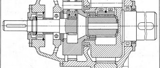
Horizontal single-stage helical gearboxes fig. 2.8.1 and vertical Fig. 2.8.2 have, as a rule, helical gearing. Gear ratio of such gearboxes u
Figure 2.8.1 Single-stage horizontal helical gearboxes
Figure 2.8.2 Single-stage helical gearbox vertical
Two-stage helical gearboxes
fig.2.8.3 – horizontal, fig. 2.8.4 – vertical. Gear ratio u = 8…40
Figure 2.8.3 Two-stage helical gearbox horizontal
Figure 2.8.4 Two-stage helical gearbox vertical
Three-stage helical gearboxes. These gearboxes are made primarily on the basis of a horizontal design. Range of gear ratios u = 31.5…180.
Bevel gearboxes Fig. 2.8.5 are used when it is necessary to transmit torque between shafts with mutually perpendicular axes. The gear ratio of such gearboxes is u ;
Figure 2.8.5 Bevel gearboxes
Bevel-helical gearboxes
Fig. 2.8.6, regardless of the number of stages and layout, is performed with a high-speed conical stage. Gear ratio u = 8…31.5.
Figure 2.8.6 Bevel-helical gearboxes
Worm gearboxes
Due to low efficiency and shorter service life than gear reducers, it is not recommended to use them in continuous machines.
The layout possibilities are limited and are reduced to three main gearbox designs: with a lower, upper and side worm arrangement (Fig. 2.8.7). The choice of gearbox design is usually dictated by the convenience of the drive layout as a whole. Range of gear ratios u = 8…80, recommended u
Figure 2.8.7 Worm gearboxes
Helical-worm two-stage gearbox
Fig. 2.8.8 has a high-speed worm stage and one worm-cylindrical or two worm-cylindrical stages with the gearbox parameters of an expanded circuit. The gearboxes have a large gear ratio and low noise level. The worm is usually located at the bottom, which is caused by the lubrication conditions of the gear, the location of the worm bearings and the assembly conditions.
Figure 2.8.8 Helical-worm two-stage gearbox
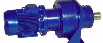
Geared motors
They are a unit that combines an electric motor and a gearbox. This is done in order to reduce the dimensions of the drive and improve its appearance.
Planetary gearboxes
allow you to obtain a large gear ratio with small dimensions. They are more complex in design than the gearboxes described above. The most common is a simple planetary gear reducer (Fig. 2.8.9.
Figure 2.8.9 Planetary gearbox
Wave reducers
are a type of planetary gearbox. Capital letters of the Russian alphabet are used to designate gears: C – cylindrical, K – conical, Ch – worm, P – planetary, V – wave.
If the gearbox has two or more identical gears, then the corresponding number is placed after the letter. Example: C (Fig. 2.8.1, 2.8.2); C2 (Fig. 2.8.3); CC (Fig. 2.8.6); H (Fig. 2.8.7); TsCh 9 (Fig. 2.8.8). If all the gearbox shafts are in a vertical plane, then the index B is added to the designation. If the axis of the low-speed shaft is vertical, then the index T is added, if the axis of the high-speed shaft is vertical, then the index B. KTst, KB Ts (Fig. 2.8.6).
Possible problems with a car gearbox and their solution
Working components fail most often in a horizontal cylindrical gearbox. After all, they wear out the most. The main reason for failure is high loads, as well as oil starvation for a long time. This can happen if there is no lubrication at all or there is not enough of it.
How to understand that a helical horizontal gearbox has failed? The main symptom is extraneous noise, hum, vibration, clicking in the areas where the bearings meet the gears. If the oil seal breaks, oil will begin to leak, it will come out through small cracks.
The housing may also be damaged and the fasteners may break. Such a malfunction occurs quite rarely, but can lead to expensive repairs. This breakdown occurs after the car hits an obstacle. Most often, after this, cracks appear in the area where the housing is attached. At first it may seem that nothing bad has happened, however, when dirt and dust particles penetrate into them, all this leads to contamination of the lubricant.
As a result, the transmission fluid loses its lubricating properties and cannot cool the parts. The mechanism begins to overheat, wear out faster, and the teeth may break. Have you noticed that the housing of the horizontal spur gearbox is damaged? Most likely, there will be a strong hum. As a result, the overall noise level will increase and driving such a car will become uncomfortable. In the area where the housing is damaged, lubricant will leak.
What to do if the horizontal spur gearbox breaks down? Strict adherence to the manufacturer's recommendations will help to avoid its complete failure. You should carry out regular maintenance of the car, pour new lubricant into the transmission on time - preferably every 100 thousand kilometers.
In what other cases is it necessary to change the oil? This should definitely be done if you are installing new oil seals. Even automakers are warning about this.
Have you noticed that the box is not working properly? Do you suspect that the breakdown occurred in a horizontal spur gearbox? Don't delay visiting the service station. Only there specialists will be able to diagnose the mechanism. If you carry out restoration work on time, you can save on the cost of repairs and maintenance.