u h1 w = z 1 × z g / / ( z 1 × z g - z m × z z )
If z m = z 1, then u h1 f = - z g / ( z f - z g)
Kinematics of the wave mechanism Let us consider an ideal frictional wave transmission. In this transmission, the contacting surfaces of the flexible and rigid wheels will correspond to the initial surfaces of the gears. We assume that the thickness of the flexible wheel is infinitesimal. Then the middle surface of the flexible wheel coincides with its initial surface. We assume that the middle surface of the flexible wheel is inextensible, that is, its length before and after the wheel is deformed by the wave generator remains unchanged.
The following notations are used in Fig. 18.8:
r wу — radius of the initial circle of a conditional wheel; r wzh is the radius of the initial circle of the rigid wheel; r d is the radius of the deforming disk; r сг is the radius of the median circle of the flexible wheel; r су — radius of the median circle of a conventional wheel; w 0 is the radial deformation of the flexible wheel.
Let us consider the movement of the links of the differential wave mechanism relative to the wave generator. Then the angular velocities of the links will change as follows:
Table 18.2
| Link | Link h | Link 0 | ||
| relative to the rack | w g | w _ | w h | w 0 =0 |
| relative to the wave generator | w * g = w g - w h | w * w = w w - w h | w h — w h =0 | — w h |
In the movement of the links relative to the wave generator, the velocities of the links are equal to the angular velocities in movement relative to the rack minus the angular speed of the generator. The speed of the rigid wheel point coinciding with the engagement pole V Pl = ( w
zh -
w
h) Ch r wzh, and the speed of the point coinciding with the pole on the flexible wheel is V Pg = (
w
g -
w
h) Ch r wg
There is no slip at the engagement pole and V Pg = V Pg, and since we consider the middle surface of the shell to be inextensible, then V Pg = V C. Then for motion relative to the wave generator
V Pzh = ( w
w -
w
h ) Х r wж ;
V C = ( w
g -
w
h ) H r wg
V Pzh = V S Yu ( w
w -
w
h ) Х r wж = (
w
g -
w
h ) Х r wг
( w
w -
w
h )/ (
w
g -
w
h ) = r wg / r wg = z g / z f ,
| z z h w w + (z g - z z ) h w h - z g h w g = 0. |
For wave gear reducer (1):
- with a braked rigid wheel w
= 0
| u hg = w h / w g = - z g / (z g - z g) |
- with a braked flexible wheel w
g = 0
| u hzh g = w h / w f = z f / (z f - z g ) |
Calculation of the geometry of wave gearing There are two main approaches to calculating the geometry of wave gearing. In the first method (2), the relative motion of the teeth is studied and, based on this, recommendations are developed for the selection of geometric parameters of engagement. The second method (3) is based on the use of the calculated internal engagement of a rigid wheel with a conditional design wheel. This wheel fits into the deformed flexible wheel in the area of possible engagement. The advantage of the first method can be considered relative versatility, which allows the deformation of both flexible and rigid wheels under load to be taken into account when calculating the geometry. However, it is difficult to develop recommendations even for a small number of CDW designs. The second method allows you to use the standard calculation of internal involute gearing for a pair of wheels z w and z y to calculate the geometry. The number of teeth of a conditional wheel is calculated using the following formula:
| zy = z g / ( 1 ± kb × mw ) |
mw = w 0 / r сг - relative deformation of the flexible wheel. kb is the coefficient determined by the angle bb is the angular coordinate of the section of constant curvature of the deformed curve of the flexible wheel.
1. Define wave gearing (page 1)
2. Is the CDW a type of planetary mechanism or is it a special type of gear? (p. 1)
3. Explain the advantages and disadvantages of VZP (p. 3)
4. What are the design features of the VZP for converting movement through a sealed wall? (p. 2)
5. How is the gear ratio of a wheel drive with movable flexible and rigid wheels determined? (pp. 7-8)
6. Draw block diagrams of CDW with U?300 and U?2500 (p. 6)
Source
Design Features
The design of a wave gearbox depends on the scope of its application. The main purpose for which this mechanism is used is to convert the input rotational motion of the motors into:
- output progressive;
- output rotational.
In their design, they are similar to planetary mechanisms since there are several contact zones with a flexible wheel. Ensures simultaneous cam contact. It has several protrusions that form waves when rotated. In this case, the load is distributed evenly over all meshed teeth. In the production of wave gearboxes, the number of teeth on the wheels varies from 100 to 600.
The place where the top of the wave of the deformable element comes into contact with another gear is called the meshing zone.
Based on the number of such zones, a gearbox with a flexible element can be:
- single-wave;
- two-wave;
- three-wave.
More waves are extremely rare.
Common faults
Gearbox failure can be avoided with proper operation and regular maintenance. You should carefully study your passport. It specifies the types of maintenance and their frequency. It is necessary to change the oil regularly and constantly top it up. Compliance with the operating mode will keep the unit intact.
The main gearbox malfunction is associated with its overheating. This happens in the absence of lubrication and the use of oils of other brands. Otherwise, the unit will overheat and the gear may jam.
Bearings have their own safety margin. Their service life is indicated in the passport. If you do not replace them with new ones in time, the nodes begin to crumble. The balls will fall out and the shaft will begin to rotate with great effort and jerking.
Between the body and the covers: top and side, along the plane of the connector, a sealant is laid during assembly. It prevents oil from leaking out. If it is not changed in time, liquid will leak from all connectors.
Overloads and sudden switching on lead to tooth destruction. When the transmission mechanism does not match the engine, it will not last long.
Principle of operation
Wave gearboxes have the following operating principle:
- A non-deformable wheel with internal teeth is mounted in the housing.
- A flexible gear with thin walls is mounted on the wave generator.
- When rotating, the wave generator deforms the flexible wheel, thereby moving the contact points of the outer and inner gears.
Smooth running is ensured by the fact that the flexible wheel has fewer teeth.
Application of equipment for different types of gas
According to the type of gas being reduced, reducers are divided into the following types:
- acetylene;
- hydrogen;
- oxygen;
- propane-butane;
- methane.
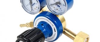
The figure shows different types of gearboxes
At the same time, all options can be divided into devices for flammable and non-flammable gases. Cylinders with a flammable gas mixture have a left-hand thread, while containers for inert gases and oxygen are equipped with a right-hand thread. This is done in order to prevent accidental connection of a reducing element, intended, for example, for methane, to an oxygen cylinder. By the way, you will find more information about autonomous gasification in this section.
For liquefied hydrocarbon gases, the design of gas reducers may have one design feature. In order to prevent freezing of the gas at the outlet, the body of the device is made with developed fins.
The quality of the gas plays a big role in the longevity of the gearbox. Therefore, tanks must be refilled from reliable ones, where, in addition to good service, you can get professional advice on working with any gas equipment.
Source
Types of Wave Reducers
Among the variety of devices of this type. The most widespread are wave geared motors. The design of such a mechanism consists of an electric motor and the wave transmission itself. Key features to look for before purchasing:
- dimensions;
- power;
- efficiency;
- maximum load.
The advantages of such devices over other types of motors:
- smaller sizes;
- low noise and vibration levels;
- resistance to loads.
The main method of lubrication of such devices is the standard supply of oil to the contacting elements. However, some situations require sealed mechanisms without the use of coolant. The flange wave reducer with a pneumatic motor operates without lubrication. In such a device, the elements are cooled using compressed air.
The worm wave gearbox has two types of placement of the worm in the housing - upper and lower. This mechanism has found application in the space industry, where tightness is required.
Used in the design of a space winch.
Wave gear transmission appeared relatively recently, but has already proven itself on the positive side. It provides greater wave deformation, thereby increasing the gear ratio. Among the advantages, it is also worth highlighting high efficiency, small size and low weight.
Maintenance and repair
The complexity of the mechanism under consideration determines that there is a need for timely maintenance and repairs.
To begin with, let us pay attention to how the calculation of a planetary gearbox is carried out. Among the features of this process, we note the following points:
The required number of transmission stages is determined. For this, special formulas are used. The number of teeth and the calculation of the satellites are determined. Gears can have a wide variety of teeth
In the case under consideration, their number is quite large, which is the determining factor. Attention is paid to choosing the most suitable material, since the main operational characteristics of the device depend on its properties. The indicator of the interaxial distance is determined. A verification calculation is made. It eliminates the possibility of making mistakes at the initial design stage. Bearings are selected
They are designed to ensure smooth rotation of the main elements. When choosing a bearing, attention is paid to the load they are designed for. In addition, it is not recommended to use this element without lubrication, as this leads to significant wear. The optimal wheel thickness is determined. Too high an indicator causes an increase in the weight of the structure, as well as costs. A calculation is made of where exactly the gear axes should be located. This is done taking into account the size of the gears and some other points. As a rule, a drawing is used as a basis, which can be downloaded from the Internet. It is quite difficult to independently develop a project for the manufacture of a planetary gearbox, since you need to have the skills of an engineer to carry out the appropriate calculations and design.
It is quite difficult to make the design in question yourself, as is repairing planetary gearboxes. Among the features of this procedure, we note the following:
- The procedure is quite complex, since the mechanism consists of a large number of different elements. An example is that immediately after disassembly, all the needles can fall out almost instantly.
- Many experts recommend entrusting the work in question exclusively to professionals, since mistakes made cause rapid wear and failure of the mechanism.
- Repairs often involve replacing gears that wear out over time. An example is abrasion of the teeth, changes in the size of the seat and many other defects. It is almost impossible to make such products yourself, since this requires special equipment.
Most often, maintenance involves adding oil. Lubrication of the planetary gearbox can significantly extend the service life of the structure, since contact and friction of the metal causes abrasion. It is recommended to lubricate the mechanism periodically, since the oil also acts as cooling. There are special lubricants on sale that are characterized by certain performance properties.
Today, gearbox repairs are carried out by companies that specialize in providing relevant services. A sign that the mechanism is beginning to fail is the appearance of strong noise, vibration, jerking, heating and much more. Over time, the wear process accelerates significantly, as the metal in the oil gets caught in the gears. In most cases, repairs involve replacing all elements with new ones.
In conclusion, we note that the planetary gearbox is characterized by very attractive properties. An example is the absence of a large number of fasteners, as well as uniform distribution of the load. As previously noted, the gearbox is used to create various vehicle components.
Wave reducer application
Due to a number of features that are not available to other mechanisms of this type, the drive with a wave gearbox has become widespread in many industries. Such a device can be found:
- in astronautics and aircraft manufacturing;
- in shipbuilding and submarines;
- in the oil production and oil refining industry;
- in chemical production;
- in nuclear power plants;
- in robotics and automated systems;
- in mining.
The tightness of the device allows it to be used in difficult climatic conditions, in vacuum and under water. Resistance to heavy loads and difficult operating conditions has found application for these devices in nuclear power and places with the possibility of explosions and earthquakes. The accuracy of the transmitted movements allows them to be used in machines with numerical control. A high safety margin and long service life allow the gearbox to be used in any production, introduced into the technological process, and used in the operation of a conveyor, automated systems and other equipment.
The simple design allows you to assemble such a mechanism with your own hands, but if the purpose of use involves the use of a gearbox in a complex technological process, it is worth purchasing professional equipment. Its cost will be significantly higher, but the manufacturer provides a guarantee for the equipment and the performance of all assigned tasks.
Wave gearboxes have many advantages, for which they are widely used. They have high efficiency, many gear ratio options, small size, high precision and smooth operation of moving parts. The high cost of such devices in comparison with other gearboxes pays off in a long service life and inexpensive maintenance.
Disadvantages of worm gearboxes and drives built on them
1. The efficiency of a worm gearbox is lower than the efficiency of a cylindrical gearbox. Moreover, the efficiency decreases with increasing gear ratio. This entails energy losses - a factor that in the modern world cannot be discounted under any circumstances. For example, the efficiency of a Russian-made Ch-80 worm gearbox with a 1:80 gear ratio is 58%. The remaining 42% are losses due to irreversible energy dissipation. This disadvantage is due to the increased sliding friction of the worm turns on the teeth of the worm wheel compared to other types of gears. In this sense, a worm gear is similar to a “sliding screw-nut” gear, which is also not characterized by high efficiency. During the running-in period under load for 200...250 hours, the efficiency can be 90% of the nominal.
2. Heating. This is a consequence of the previous shortcoming. That kinetic energy that was not transferred by the worm gear is converted into heat. It’s not for nothing that the housings of worm gearboxes have ribs that make them look like central heating radiators. Some large worm gearboxes are supplied with fan impellers on the free end of the high-speed shaft. In other cases, it is necessary to organize forced oil circulation in the gearbox housing. The above applies to gearboxes with high transmitted power (over 4...5 kW). In lower power applications, additional heat dissipation measures are generally not required. However, heating of the worm gear housing during its operation always occurs.
3. Self-braking (for more details, see paragraph 5 “advantages”). Its appearance is sometimes harmful - in cases where the output shaft needs to be turned without turning on the worm gear drive.
4. Limitations on transmitted power. Technical literature does not recommend using a worm gear with a transmitted power of more than 60 kW (source - Handbook of mechanical engineering designer V.I. Anuryev, vol. 2, p. 606, 2001 edition). Worm gearboxes for higher power, however, do exist. These are mainly globoid worm gearboxes used in special cases (for example, elevator and hoist drives). And yet, when choosing a gearbox for such power, it is recommended to give preference to cylindrical types of gearboxes. As far as I know, leading foreign manufacturers of worm gearboxes mostly produce worm gearboxes for power transmission up to 15 kW.
5. Output shaft play. Such play exists in any type of gearbox, however, in worm gearboxes its value is usually greater and increases with wear.
6. The service life of worm gearboxes is generally considered lower than that of cylindrical gearboxes. This is a very conditional statement, but due to the presence of increased sliding friction in the mesh compared to other types of gearboxes, wear does occur. Russian manufacturers of gearboxes provide the following data on the operating life parameters of gearboxes with different types of gears:
7. Operation of the worm gearbox under conditions of uneven loads on the output shaft, as well as with frequent starts and stops, is not recommended.
Purpose of the cylinder propane reducer BPO 5-2
The BPO 5-2 propane reducer is used to reduce and stabilize the pressure of household gas supplied from standard cylinders to consumers such as welding torches and cutters, heaters and a large number of other types of consumers.
Design and principle of operation of the propane reducer BPO 5-2
This propane reducer is built according to a single-chamber design; at the inlet it has a pipe with a threaded union nut for connection to the cylinder. The body is cast from aluminum alloy, the body cover is made of polyamide.
https://youtube.com/watch?v=eXophZ3QC3M
A special feature of the propane reducer is its small size and weight, which makes the BPO 5-2 convenient for transportation and storage.
Technical characteristics of propane reducer BPO 5-2
The propane reducer is produced by the oldest manufacturer of gas equipment in the country -:
Technical characteristics of gearboxes
- Weight 0.34 kg.
- Length × width × height 135 × 105 × 96mm.
- Operating temperature -15+45˚С.
- Maximum inlet pressure 25 kg/cm3.
- Working pressure 3 kg/cm3.
- Maximum gas consumption, 5 m3/hour.
- Connection method W 21.8-14 threads per 1″ LH.
- Working connection M16x1.5 LH.
Complete set of propane gas reducer BPO 5-2
Package Included:
- Propane reducer assembly.
- Technical certificate.
- Nipple for sleeve 6.3 or 9 mm.
- Package.
Safety precautions when working with propane reducer BPO 5-2
Propane is a source of increased danger. In order to consciously follow safety requirements, you need to understand exactly what threats the gas itself and the devices that use it pose:
Safety precautions when working with propane reducer BPO 5-2
- First of all, propane is flammable. Improper handling can cause a serious threat to the life and health of people, as well as material values.
- You can't breathe propane. A person dies in a propane atmosphere. If small amounts are inhaled, it causes poisoning, causing headaches and vomiting.
- Propane is explosive under certain conditions; when a certain concentration of propane in the air is reached, a volumetric explosion occurs. An explosion also occurs when the temperature in the cylinder rises sharply.
- When propane quickly leaks from a cylinder into the atmosphere, a strong drop in temperature occurs, which can lead to severe and deep frostbite.
Rules for working with a propane cylinder
To avoid these unpleasant consequences, the following rules must be observed when working with propane:
- Do not handle propane near open flames or high heat.
- Do not bring other flammable substances into the work area.
- Do not use materials that are chemically incompatible with propane, such as nitrates and perchlorates, near propane.
- Do not use gas equipment and fittings that have visible mechanical damage and signs of gas leakage.
Operating rules for propane reducer BPO 5-2
The operating rules contain, first of all, requirements for strict compliance with the safety measures listed above.
Each time before starting operation, it is necessary to inspect the propane reducer, connecting fittings, and supply hoses for mechanical damage and visible and audible signs of leakage. If such signs are detected, it is unacceptable to begin operation; damaged equipment must be repaired or replaced.
Rules for operating a propane reducer
If the pressure gauge needle does not move or, on the contrary, jumps at a constant gas flow rate, it is faulty and must be replaced.
It is also necessary to carefully monitor the timing of the scheduled verification of the pressure gauge of the propane reducer for compliance with the passport technical requirements. Such verification must be carried out by a special certified organization at least once every five years.
In addition, it is necessary to follow the procedure for connecting the propane reducer to the cylinder and to consuming devices. At least once a month you need to check the condition of the filter and clean it if necessary.
Operating principle
The operation of such a gearbox is based on the principle of equalizing the forces of the diaphragm and the tuning spring. When you open a tap in the water supply, the output pressure of the reducer decreases, which leads to a decrease in pressure on the diaphragm. In this case, the spring force turns out to be large, and, leveling it, it simultaneously opens the working valve until the operating pressure at the outlet becomes equal to the specified value. In this case, the pressure at the inlet of the gearbox, as well as its surges, do not in any way affect the opening or closing of the valve. A reducer installed on the inlet pipe reduces to the required level and stabilizes the pressure in the entire water supply system of a house or apartment. If this was not done when installing the system, then you can install the reducer separately on a boiler, dishwasher or washing machine, which are usually not designed for high pressure
It is especially important to do this if there is a pump in the system, when turning it on and off a water hammer occurs.
Conditions of use:
- Aqueous medium free of oil and compressed air.
- Maximum pressure no more than 16 bar.
- Maximum temperature no more than 70 °C.
Which gearbox should I choose?
If you are working on a machine that needs to perform precise work at an intense pace, a planetary gearbox is better suited for the task. It removes vibration well, is capable of high-quality splitting of the pitch and practically reduces the load on the engine.
The belt reducer is not intended for precise, almost jewelry reduction, so it is used in industries where detailed work on all the parameters of the torque and the engine that creates it is not required.
Purpose and principle of operation of wave transmissions.
Wave transmissions are based on the principle of transmitting rotational motion due to the traveling wave deformation of one of the gears.
This transmission was patented by the American engineer Masser in 1959.
Wave transmissions have smaller mass and dimensions, greater kinematic accuracy, less backlash, high vibration strength due to damping (energy dissipation) of vibrations, and create less noise.
If necessary, such transmissions make it possible to transmit movement into a sealed space without the use of sealing seals, which is especially valuable for aviation, space and underwater equipment, as well as for chemical industry machines.
Kinematically, these gears are a type of planetary gear with one flexible gear.
Basic elements of wave transmission:
- fixed wheel with internal teeth,
- rotating elastic wheel with external teeth,
- drove.
What parameters should you pay attention to when choosing a gearbox?
Before choosing a gearbox for a CNC machine, you need to understand what operating parameters you expect from the transmission. Calculation of the loads that the gearbox will encounter will be an important factor when analyzing the overload coefficient permissible for the mechanism.
Conclusion
The conditions in which the machine will operate (humidity, temperature) and the availability of free space in the working area are also of great importance. The more information the client provides to the service, the more accurately it will be possible to determine the ideal reduction device for the machine.
Classification according to main characteristics
Modern engineering and technical standards provide for the classification of gearboxes according to the following criteria:
- design of the transmission used;
- spatial arrangement of elements;
- design.
Based on the spatial arrangement of key elements, these devices are divided into vertical and traditional horizontal gearboxes. The design provides two additional types: a pure mechanical gearbox, and a gearbox with a propulsion system (geared motor). However, the generally accepted classification of gearboxes is considered to be based on the type of transmission unit (gear) used.