Advantages and disadvantages
Worm gears, due to their design features, have both advantages and disadvantages.
Among the advantages, it is worth noting the smooth running, self-braking effect, low noise level, large gear ratio using only two parts.
Among the disadvantages, attention should be paid to the relatively low efficiency, increased wear, jamming, and high heat generation due to friction forces. Low efficiency determines the use of such mechanisms when transmitting relatively small powers up to 100 kW. To prevent rapid wear and jamming, it is necessary to comply with the requirements for assembly accuracy and adjust the mechanisms. High heat generation requires special installations to remove excess heat.
The difference between gearboxes mainly comes down to the differences in the worms and gears from which a given worm gearbox is assembled.
Worms are divided into types according to the following characteristics:
- by number of thread starts: single-start, multi-start
- in the direction of thread cutting: right, left
- according to the shape of the screw on which the thread is cut: cylindrical, globoid
- according to the shape of the thread profile: with a convolute profile, with an Archimedean profile, with an involute profile
- Gears are divided into types according to the following characteristics:
- by wheel type: wheel itself, gear sector, degenerate sector
- according to the profile of the teeth: straight, concave, roller (a rotating roller is used instead of teeth)
Worm gearboxes with a built-in motor are called worm gearmotors. In gearboxes, the motor shaft is most often located at right angles to the movable one. The layout of the worm gearbox is selected based on the specific requirements for the devices. The engine can be located either on top of the driven wheel, or below and on the side. When positioned sideways, the engine is installed vertically. Due to the vertical location, the process of lubrication of the shaft bearings, as well as cleaning of external elements, is complicated.
Various technologies are used to increase the gear ratio, but the most effective is the use of a larger number of stages.
To soften friction forces and increase resistance to seizing, special viscous lubricants or oils are used. At low rotation speeds, lubrication is carried out using special oil baths or using special devices that spray lubricant into areas of high friction. For worm gearboxes, the rotation speed of which is high, the use of baths is impractical, and forced lubrication with cooled lubricants is used.
The main advantages of a worm gearbox over gears are that the initial contact of the links occurs not at a point, but along a line. Also, the input and output shafts can cross at different angles, but most often this angle is 90 degrees. Also, a worm gear takes up much less space than a toothed gear with the same large gear ratio.
In addition to the worm gearbox, the worm gear is also used in regulation and control systems for various devices. Thanks to self-braking, precise position fixation is ensured, and a large gear ratio (up to 1000) allows you to most accurately adjust the position, or use low-power motors. Also, worm gears and worm gearboxes are excellent for installation as a transmission mechanism in lifting and winching mechanisms due to their design features.
Some technical characteristics of industrially produced and widely used worm gearboxes.
The most common are single-stage geared motors.
| Type | Gear ratio | Output shaft rotation speed rpm | Rated output torque Nm | |
| gearbox | gear motor | |||
| Ch-20 | MCH-20 | 5 — 50 | 28 — 300 | 4 |
| Ch-25 | MCH-25 | 6 | ||
| Ch-31.5 | MCh-31.5 | 8 | ||
| 2H-40 | MCH-40 | 5 — 80 | 9,37 — 300 | 28 — 37 |
| Ch-50 | MCH-50 | 50 — 70 | ||
| 1Ch-63, 2Ch-63 | MCH-63 | 5 — 80 | 7,5 — 300 | 95 — 135 |
| 1Ch-80, 2Ch-80, Ch-80 | MCH-80 | 150 — 280 | ||
| Ch-100 | MCH-100 | 315 — 570 | ||
| Ch-125 | MCH-125 | 615 — 1000 | ||
| Ch-160 | MCH-160 | 1100 — 1900 | ||
| Ch-200 | MCH-200 | 1600 — 3100 | ||
| Ch-250 | MCH-250 | 2700 — 5700 | ||
| Ch-320 | MCH-320 | 4400 — 10000 | ||
| Ch-400 | MCH-400 | 6500 — 19000 | ||
| Ch-500 | MCH-500 | 8200 — 33000 | ||
| RCHN-180 | MRCHN-180 | 12,5 — 50 | 20 — 90 | 1300 — 1800 |
| RChP-300 | MRChP-300 | 16, 25, 50 | 20 — 40 | 4200 |
A worm gearbox is a transmission mechanism that serves to reduce angular speed and increase torque. In this case, in a worm gear, motion is transmitted between shafts intersecting at right angles.
Single-stage worm gearboxes find their use in the range of gear ratios u = 8...80 (and in non-power transmissions up to 200 or more). If one gear is not enough to provide the required gear ratio, another worm gear is mounted in the gearbox housing or together with the worm gear of another type (cylindrical, conical).
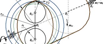
From the point of view of geometry and kinematics, worm gears combine the properties of gear transmissions and screw pairs. The combination of features of various mechanisms determines the characteristics of the worm gear and approaches to transmission design.
FEATURES AND MAIN PARAMETERS OF WORM GEARS
The worm gear consists of two links. The driving link is worm 1, the driven link is worm wheel 2.
The interaction of the elements of a worm pair is similar to the principle of operation of a screw mechanism, in which the worm is a screw, and the worm wheel is a narrow sector of a long nut, bent in a ring with teeth outward around an axis perpendicular to the axis of the screw.
The main advantages of worm gears include:
• the ability to implement large gear ratios (usually from 8 to 63, and in non-power transmissions up to 200 or more) in one stage with relatively small dimensions;
• High smoothness of engagement and quiet operation;
• High kinematic accuracy;
• The impossibility of transmitting movement in the opposite direction (from the wheel to the worm) due to self-braking of the transmission (as a result, for example, there is no need to use braking devices in lifting mechanisms).
The main disadvantages of worm gears, which significantly limit the scope of application of the gears (in particular, in terms of transmitted power - usually no more than 50 - 60 kW), are considered to be:
• Low efficiency (η ≤ 0.92) due to large power losses due to the relative sliding of the mating surfaces of the worm and worm wheel under load;
• Increased heating and wear;
• The need to use expensive antifriction materials;
• Increased requirements for the accuracy of mechanism assembly and the need to adjust the gearing.
The noted advantages and disadvantages are due to the peculiarities of the geometry and kinematics of the engagement (a combination, as already noted, of the characteristics of transmission by engagement and a screw pair).
It is customary to consider two main factors that determine the properties of a worm gear:
1 – high relative sliding speed in contact between the surfaces of the worm turns and the teeth of the worm wheel, which determines large power losses due to friction and, as a consequence, increased heating and low transmission efficiency;
2 – unfavorable conditions for the formation of an “oil wedge” in the contact between the worm and the worm wheel, which, together with heating, makes the transmission prone to jamming, wear and the need to use expensive antifriction materials.
Note: By “oil wedge” we mean the creation of increased oil pressure in the wedge gap between the contacting surfaces.
Attempts to improve the quality performance of worm gearboxes have led to the emergence of various types of worm gears.
Gears are divided according to the shape of the worm surface on which the turns are cut: gears with cylindrical and globoid worms.
Globoid worm gears have a higher load capacity, but are more difficult to manufacture, install and operate, and also heat up more during operation. They require high production standards and are used in critical mechanisms.
Cylindrical worm gears, based on the shape of the helical surface of the worm turns, are divided mainly into gears with an Archimedean worm, involute and convolute. It is almost impossible to determine the difference in the types of helical surface of worms by external signs without special instruments, therefore the task of determining the shape of the worm surface is not set in this laboratory work.
All cylindrical worm gears are characterized by the same set of geometric parameters and their dimensions are determined by the same ratios. The main geometric parameters of the worm gear, which make it possible to calculate the main dimensions of the worm and worm wheel, select tools and set up a machine for cutting a worm pair, include:
Module m , mm - is defined as the ratio of the axial pitch of the worm to the number π (m = р/π). By axial step p we mean the distance between the same points of two adjacent profiles, measured in the direction of the worm axis. The size of the module must correspond to the standard series (GOST 2144-76*);
The number of turns (approaches) of the worm z1 is taken depending on the gear ratio: z1 = 4 at u = 8...15, z2 = 2 at u = 15..30 and z1 = 1 at u ≥ 30.
Number of wheel teeth z2 . From the condition of not cutting the teeth of the worm wheel during cutting, z2 ≥ 28 is taken. Z2 = 32…63 is considered optimal for power transmissions;
Worm diameter coefficient q is defined as the ratio of the pitch diameter of the worm d1 to the module (q = d1/m). The value of q must correspond to the standard (GOST 2144-76*) series and be combined with the module.
The need to standardize the values of the module and diameter coefficient is due to the desire to reduce the range of cutting tools, since the worm cutters used in most cases for cutting worm wheels must fully correspond to the worm that engages the wheel in gear, i.e., have the same module and pitch diameter;
Worm displacement coefficient x . The offset is mainly used to fit the gear into the standard center distance.
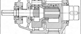
DESIGN FEATURES OF WORM REDUCERS
The design of worm gearboxes as a whole and their individual components is determined by the layout of the transmission mechanism and the characteristics of the gearing.
Housing design. The most widely used designs are worm gearboxes with a housing split along the axis of the worm wheel. This simplifies the assembly of the shaft kit with bearings and worm wheel. The worm usually has a small outer diameter of the turns, which allows it to be installed in the housing through the holes of the bearing seats.
Small gearboxes (à ≤ 120 mm) are often made without a connector with removable side covers. According to the assembly conditions, the holes for the centering protrusions of the covers must slightly exceed the outer diameter of the wheel, and the overall dimensions of the internal cavity must allow the worm and wheel shafts to move apart during installation and dismantling.
Cooling. Due to the high friction in the meshing, the operation of the gearbox is accompanied by significant heating, therefore, for better cooling of the gearboxes, the housings are usually made with ribs (increasing the heat transfer surface), and if this is not enough, artificial cooling is used (forced ventilation, oil cooling inside or outside the gearbox).
Worm location. In mechanical engineering, gearboxes with different arrangements of the worm relative to the wheel are used: with the bottom, with the top, with the side horizontal and the side vertical. The upper location is usually used at high speeds of rotation of the worm shaft, and the lower one, respectively, at low speeds, but more often the choice of the worm position is determined by the layout of the mechanism.
Design of gear elements
Worms are most often made together with a shaft, using carbon or alloy steels with surface or bulk hardening to high hardness (more than 45 HRC).
Worm wheels are usually made of composite wheels, which reduces the cost of transmission. The wheel hub is made of gray cast iron (less commonly, steel), and the ring gear is made of antifriction material (bronze, brass, cast iron). The choice of the type of crown material depends on the sliding speed in the mesh and the duration of operation. The higher the sliding speed, the higher the anti-friction and extreme-scuff properties the wheel tooth material should have.
The following typical worm wheel designs are used in mechanical engineering: banded, bolted and bimetallic. The latter is the most rational; it is used in mass-produced machines.
Construction of supports. The worm shaft is subject to radial and very significant axial loads, so tapered roller bearings are usually used as supports, and at high rotation speeds (over 1500 rpm), it is possible to use angular contact ball bearings (which have less rotational resistance).
Relatively short worm shafts are usually installed according to the “off-the-cuff” scheme, in which the left bearing prevents the shaft from moving to the left, and the right one, respectively, to the right.
Long worm shafts (l / d > 6, where l is the distance between the supports, d is the diameter of the shaft) are installed in bearings so that one of the supports (fixing) takes axial loads acting in both directions, and the second (floating) can to move freely in the axial direction in the housing. This makes it possible to eliminate the selection of axial clearances and jamming of bearings when the shaft length increases due to heating.
The axial position of the wheel must be maintained during operation under load, therefore, in power transmissions, the wheel shaft is usually installed on tapered roller bearings with increased rigidity.
ADJUSTING THE WORM REDUCER
Traditional technologies for manufacturing worm gearboxes require its adjustment during the assembly process.
The need to adjust the worm gear during the assembly process is due to the limited accuracy of the axial linear dimensions of the gearbox parts, which, as a rule, does not allow knowingly ensuring during assembly the correct axial position of the wheel relative to the worm, as well as the clearance in the bearings necessary for normal operation.
The discrepancy between the average plane of the wheel and the axis of rotation of the worm leads to a displacement of the contact patch in engagement to the edge of the tooth, which creates unfavorable conditions for the operation of the gear.
With out-of-adjustment bearings, two situations are possible:
1. If there is excess clearance in angular contact tapered bearings, radial and axial mobility (play) of the shaft during operation is inevitable, which negatively affects the operation of the transmission and the bearings themselves;
2. If there is no clearance or, even worse, excessive tightening of the bearings (with tension), during operation of the gearbox (when it heats up and the inevitable elongation of the shafts), overload of the bearings may occur, their heating with subsequent failure of the bearings themselves and, consequently, the mechanism as a whole.
When adjusting the gearbox, there are two stages: adjusting the bearings and adjusting the gearing.
Worm shaft. Only the bearings are adjusted. The axial position of the worm does not affect the operation of the transmission. Adjustment is carried out by selecting the appropriate number of steel gaskets for the flanges of the bearing caps.
To determine the total thickness bΣ of the gasket set it is necessary:
• Press one of the worm shaft bearing caps against the gearbox housing, tightening the bolts firmly;
• Tighten loosely (without force) the two bolts securing the second shaft cover located on the opposite side of the housing;
• Measure the gap between the flange of the second cover and the body;
• Select a set of gaskets with a thickness equal to the measured gap;
• Divide the resulting set of gaskets into two approximately equal parts, install them under the bearing caps and tighten the cap bolts to the calculated torque.
At the same time, easy (without effort) rotation of the shaft is achieved. The permissible axial play is in the range of 20-40 microns (depending on the size and design of the unit). The absence of backlash is undesirable, since during operation of the gearbox, due to thermal elongation of the worm shaft, the gaps decrease, disappear, or even the appearance of interference in the bearings with their subsequent jamming.
Note: the optimal bearing adjustment is when the gearbox, heated to operating temperature, has a bearing clearance close to zero.
Worm wheel shaft. Adjustment of the axial position of the worm wheel can be done according to two schemes:
1. Axial displacement of the shaft with a wheel attached to it, followed by fixation of the shaft;
2. Axial movement of the wheel along a stationary shaft with subsequent fixation of the wheel.
In cases where there is one wheel on the shaft, the position of which needs to be adjusted, the first scheme is used. In accordance with this scheme, the worm wheel shaft is adjusted in two stages. First, the shaft bearings are adjusted (see worm shaft), during which
the total thickness of the gasket set bΣ is determined.
Then the gearing is adjusted in the following sequence:
• Divide the set of shims selected during bearing adjustment into two approximately equal parts and install them under the worm wheel shaft bearing caps;
• Cover the turns of the worm with a thin layer of paint (for example, a mixture of linen blue and machine oil);
• Assemble the gear and rotate it by the worm, braking the end of the wheel shaft;
• Establish (visually through the inspection hatch) the quality of engagement by the position, shape and size of the contact patch on the gear teeth; in case of an unsatisfactory result, determine the direction of the required axial shift of the worm wheel with the shaft;
• Axial displacement of the wheel shaft is carried out by shifting spacers from one side of the housing to the other, towards which it is necessary to shift the worm wheel.
Note: the given sequence (except for the first point) should be repeated until satisfactory quality of engagement is obtained.
24.06.2021
Types of worm gearboxes
Worm gearboxes can vary significantly depending on the application of the mechanism.
The main differences that can be used in the design:
- Different number of visits;
- Part material;
- Thread direction;
- Thread profile;
- Types of screw used.
These differences may be present in various combinations. The engineer decides what types of worm gearboxes to use at the design and development stage of devices and mechanisms that use these types of torque transmission.
Disadvantages of worm gearboxes and drives built on them
1. The efficiency of a worm gearbox is lower than the efficiency of a cylindrical gearbox. Moreover, the efficiency decreases with increasing gear ratio. This entails energy losses - a factor that in the modern world cannot be discounted under any circumstances. For example, the efficiency of a Russian-made Ch-80 worm gearbox with a 1:80 gear ratio is 58%. The remaining 42% are losses due to irreversible energy dissipation. This disadvantage is due to the increased sliding friction of the worm turns on the teeth of the worm wheel compared to other types of gears. In this sense, a worm gear is similar to a “sliding screw-nut” gear, which is also not characterized by high efficiency. During the running-in period under load for 200...250 hours, the efficiency can be 90% of the nominal.
2. Heating. This is a consequence of the previous shortcoming. That kinetic energy that was not transferred by the worm gear is converted into heat. It’s not for nothing that the housings of worm gearboxes have ribs that make them look like central heating radiators. Some large worm gearboxes are supplied with fan impellers on the free end of the high-speed shaft. In other cases, it is necessary to organize forced oil circulation in the gearbox housing. The above applies to gearboxes with high transmitted power (over 4...5 kW). In lower power applications, additional heat dissipation measures are generally not required. However, heating of the worm gear housing during its operation always occurs.
3. Self-braking (for more details, see paragraph 5 “advantages”). Its appearance is sometimes harmful - in cases where the output shaft needs to be turned without turning on the worm gear drive.
4. Limitations on transmitted power. Technical literature does not recommend using a worm gear with a transmitted power of more than 60 kW (source - Handbook of mechanical engineering designer V.I. Anuryev, vol. 2, p. 606, 2001 edition). Worm gearboxes for higher power, however, do exist. These are mainly globoid worm gearboxes used in special cases (for example, elevator and hoist drives). And yet, when choosing a gearbox for such power, it is recommended to give preference to cylindrical types of gearboxes. As far as I know, leading foreign manufacturers of worm gearboxes mostly produce worm gearboxes for power transmission up to 15 kW.
5. Output shaft play. Such play exists in any type of gearbox, however, in worm gearboxes its value is usually greater and increases with wear.
6. The service life of worm gearboxes is generally considered lower than that of cylindrical gearboxes. This is a very conditional statement, but due to the presence of increased sliding friction in the mesh compared to other types of gearboxes, wear does occur. Russian manufacturers of gearboxes provide the following data on the operating life parameters of gearboxes with different types of gears:
- Worm drives - at least 10,000 hours;
- Helical gearboxes - at least 25,000 hours (data, St. Petersburg).
7. Operation of the worm gearbox under conditions of uneven loads on the output shaft, as well as with frequent starts and stops, is not recommended.
Worm Gear Design
It is almost impossible to make a worm gearbox with your own hands. The calculation of the worm gear must be carried out by a qualified specialist. When the drawing is made, all parts according to it are made only from materials of proper quality, otherwise the gear mechanism may fail after a short period of work. The assembly of the worm gearbox should also be carried out by an experienced craftsman. Failure to comply with this rule can significantly reduce the service life of the part, because in addition to the correct installation of the shafts, careful adjustment of the worm mechanism will be required.
If it is necessary to use a worm gear in order to install a homemade torque transmission mechanism, then in this case it is better to use ready-made used products from equipment that uses a similar type of torque transmission. In the case when independent development of new devices that will be patented is carried out, the design of a worm gearbox should be ordered from a design bureau engaged in such developments.
Principle of operation
The basis of the entire transmission mechanism is a worm-shaped drive screw, in honor of which these types of gearboxes got their name. The worm screw interacts with a gear whose axial shaft is located at a right angle. As a result of this coupling, a high rotation speed of the input shaft with low torque is transformed into rotation of the output shaft with a low frequency but much greater force. The layout of the worm gearbox can be different. If the worm gear shaft rotates at a speed below 5 m/s, then the worm is located at the bottom, if the speed is higher, then a gearbox with an upper worm is installed.
Most mechanisms of this type are used with a single gear stage, but sometimes a two-stage worm gearbox can be used to control the ratio.
If the shaft rotation speed is more than 10 m/s, the bearings and hypoid gears must be lubricated under pressure. If the engine is low-speed, then natural oil circulation when the gear rotates is sufficient.
Oil for worm gearboxes must be of high viscosity, otherwise the wear process of the most loaded parts of the gearbox will be significantly accelerated.
Worm gear cutting technology
The worm gear model is created during the product design process. Based on the diagram, you can determine the cutting method:
- end;
- cutter feed from below.
Face cutting of worm wheels requires a tool completely similar to a worm. The device allows processing with high precision. It is difficult to insert the cutter from below. It is necessary that its position relative to the shaft exactly matches the worm.
On the crown, teeth are cut using cutters having the same outer diameter as the worm. The tool follows the shape of the leading element, but the line is not continuous, instead there are rows of cutters.
The configuration of the cutting plate must exactly replicate the thread, and it must be wider by the amount of the gap. As a result, the shape of the worm wheel is precisely similar to the shape of the thread. Its depressions completely coincide with the protrusions of the threads.
The cutter is positioned in the axial plane of the worm, touching the surface of the product. The rotation of the ring gear occurs around its own shaft or vertical mandrel. This ensures tangential feed of the outer surface along the axis of the cutter.
The cutting of worm gears is carried out in synchronous movement of the part and the tool, turning around their own axes. The rotation speed is set by the gear ratio. Each revolution of the crown moves it closer to the rotating cutter.
The cutting tool is fed both from above and from below. In practice, preference is given to radial cutting. The method is the most convenient and highly accurate.
Repair cutting is performed when it is necessary to make one part for replacement in the gearbox. It is not always possible to find a cutter of the required diameter in workshops. When using a larger tool, the fit will become worse and the contact patch will decrease. Cutting with a smaller diameter cutter will increase the load on the upper part of the thread. In both cases, a wheel repaired in this way will have high wear and friction. The efficiency will also drop. Therefore, cutting must be done with cutters with exactly the same diameter.
Steering
It is used in cars not only in axles, but also in the steering system. In fact, the liquid steering gear is the oldest system that has gone through many changes, but its technical principle has remained the same.
The steering gear in a car is used to make it easier to turn the steering wheel, even in a car without power steering.
The steering gearbox has a number of advantages, the main one being the large energy transfer ratio. We can say that the advantages include the low noise of the gearbox and smooth operation. The steering gear also has disadvantages, the main of which is rapid wear of the chain mechanism and excessive heat generation. The drive for the steering energy converter is the steering wheel.
Gearbox lubrication system
Each such vehicle unit has a lubrication system. Oil is supplied under pressure to the bearings and chain mechanism. In addition to its direct responsibility, the lubrication system cools and removes excess wear elements from the gearbox housing, which can render the chain gears unusable. These elements leave the system with the oil and are retained by the filter.
To prevent oil from leaking out of the gearbox housing, special seals are required. Special oil seals in the car are not only in this system. These seals are found wherever a seal is required. In order for the seals to create a tight seal, the seals must be installed correctly. Replacing oil seals is the same complex procedure as repairing a gearbox. The first reason that oil seals need to be replaced is a trace of oil on the housing.
Operating principle
The main feature of the worm system - self-braking - makes it especially relevant for completing production and industrial (professional) equipment. Due to self-braking, the gear begins to move under the influence of the screw (worm), but it itself does not rotate the screw.
The principle is based on the interaction of two functional elements:
- The leading worm receives rotational energy from the motor and converts it. It has the shape of a screw.
- The driven wheel receives the converted energy from the worm and “spins” the output shaft.
Gearbox repair
Simple worm gear repairs can be done on your own. If the motor and drive are combined in one housing, then the mechanism should be carefully disassembled.
The part of the common crankcase in which the drive is located must also be disassembled. If the worm drive design is made for a high-speed motor, then before proceeding with disassembling the gearbox, it is necessary to drain the transmission oil from the housing.
This type of gearbox uses high-quality bearings, so most often the need for repair occurs if the gear and worm are worn beyond the limit values. The working pair must always be simultaneously replaced with a complete repair kit, which, before entering the distribution network, must be correctly selected and tested on a special stand.
If the wear of the worm pair is insignificant, then the gap can be eliminated using special spacer washers on the driven shaft.
The design of the worm gear also allows for adjustment of the engagement of the gear with the worm without disassembling the housing. For this purpose, a bolt is used that is built into the housing. If you have a drawing of the device, you can easily determine where the gear is adjusted. If there is no drawing, then an indirect sign of the adjusting bolt will be the presence of a lock nut on it, which is used to fix the adjusted gap between the worm and the gear. It is extremely rare that gearbox bearings require replacement. Typically, the drive is equipped with high-quality ball bearings that do not require replacement or repair throughout the entire service life of the part. Bearings can only be damaged if the drive has been used for a long time without lubrication or with the use of low-quality lubricants.
Basic data
The worm gear is the main transmission component. It is a conical, cylindrical disk with teeth located on its upper plane. With the help of the latter, during rotation, the gear engages with the worm, which allows the rotational moment to be transferred from the shaft with the gear to another spindle.
The teeth of one element push counterparts on the other, which drive their axis. The shaft on which the worm is located begins to rotate and transmit movement to other structural elements. The device or installation begins to function and perform its tasks.