GOST 18360-93
INTERSTATE STANDARD
SHEET GAUGES-STAPPS FOR DIAMETERS FROM 3 to 260 mm
DIMENSIONS
INTERSTATE COUNCIL FOR STANDARDIZATION, METROLOGY AND CERTIFICATION
Minsk
Preface
1. DEVELOPED by Gosstandart of Russia
INTRODUCED by the Technical Secretariat of the Interstate Council for Standardization, Metrology and Certification
2. ADOPTED by the Interstate Council for Standardization, Metrology and Certification on October 21, 1993.
The following voted for adoption:
| State name | Name of the national standardization body |
| Republic of Kyrgyzstan | Kyrgyzstandard |
| The Republic of Moldova | Moldovastandard |
| Russian Federation | Gosstandart of Russia |
| The Republic of Tajikistan | Tajikstandard |
| Turkmenistan | Turkmen State Inspectorate |
| Ukraine | State Standard of Ukraine |
3. By Decree of the Committee of the Russian Federation on Standardization, Metrology and Certification dated June 2, 1994 No. 160, the interstate standard GOST 18360-93 was put into effect directly as a state standard of the Russian Federation on January 1, 1995.
4. INSTEAD OF GOST 18360-73, GOST 18361-73, GOST 18362-73, GOST 18363-73, GOST 18364-73
5. REPUBLICATION. September 2005
INTERSTATE STANDARD
| SHEET GAUGES-STAPPS FOR DIAMETERS FROM 3 to 260 mm Dimensions Plate snap-guages for diameters from 3 to 260 mm. Dimensions | GOST 18360-93 |
Date of introduction 01/01/95
This standard applies to smooth sheet single-sided and double-sided double-sided clamp gauges for testing shafts with diameters from 3 to 260 mm.
Clip gauges for diameters from 3 to 180 mm are designed to control shafts with tolerances according to the ESDP of the 6th and rougher grades and according to the OST system of the 2nd and rougher accuracy classes; for diameters over 180 to 260 mm - for monitoring shafts with tolerances according to the ESDP of the 8th and rougher grades and according to the OST system of the 3rd and rougher accuracy classes.
The requirements of this standard are mandatory, except for paragraphs. (notes), (last paragraph), .
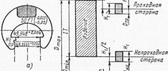
1. The design and main dimensions of one-sided staple gauges must correspond to those indicated in Figure 1 and Table 1, double-sided staple gauges - in Figure 2 and Table 2.
Single-sided clamp gauges for diameters from 3 to 10 mm
* Recommended sizes.
Single-sided staple gauges for diameters St. 10 to 100 mm
* Recommended sizes.
Single-sided staple gauges for diameters St. 100 to 260 mm
1
- frame;
2
— handle-plate according to GOST 18369
Picture 1
Notes
1. Gauge gauges with a diameter of up to 20 mm inclusive are manufactured without handles.
2. It is allowed not to make holes with a diameter of 3 - 5 mm in gauges-staples to control the diameters of the St. 3 to 100 mm.
Table 1
Dimensions, mm
| D nom | D 1 | N | h | l | l 1 | l 2 | s | Weight, kg, no more |
| From 3 to 10 | 38 | 36 | 15 | — | 6 | 3 | 4 | 0,03 |
| St. 10 to 20 | 60 | 55 | 24 | 18 | 11 | 5 | 0,09 | |
| St. 20 to 30 | 75 | 68 | 30 | 20 | 13 | 0,14 | ||
| St. 30 to 40 | 95 | 82 | 37 | 22 | 0,20 | |||
| St. 40 to 56 | 120 | 100 | 44 | 25 | 15 | 6 | 0,36 | |
| St. 56 to 70 | 140 | 118 | 50 | 28 | 17 | 4 | 0,47 | |
| St. 70 to 85 | 160 | 135 | 55 | 32 | 20 | 0,58 | ||
| St. 85 to 100 | 180 | 150 | 59 | 36 | 21 | 6 | 0,70 | |
| St. 100 to 120 | 215 | 170 | 65 | 40 | 24 | 7 | 1,00 | |
| St. 120 to 140 | 240 | 185 | 70 | 1,16 | ||||
| St. 140 to 160 | 265 | 200 | 75 | 8 | 1,57 | |||
| St. 160 to 180 | 285 | 215 | 80 | 1,73 | ||||
| St. 180 to 205 | 320 | 245 | 85 | 50 | 27 | 10 | 2,09 | |
| St. 205 to 230 | 350 | 265 | 90 | 2,36 | ||||
| St. 230 to 260 | 380 | 280 | 95 | 2,64 | ||||
| Note - For boundary size intervals D nom | ||||||||
Double-sided staple gauges for diameters from 3 to 10 mm
* Recommended sizes.
Figure 2
Note - It is allowed not to make holes with a diameter of 3 - 5 mm.
table 2
Dimensions, mm
| D nom | d | L | l | l 1 | N | Weight, kg, no more |
| From 3 to 6 | 8 | 40 | 10 | 8 | 25 | 0,03 |
| St. 6 to 10 | 12 | 50 | 12 | 10 | 32 | 0,04 |
2. Designation of one-sided clamp gauges for diameters of St. 10 to 260 mm - in accordance with the table.
Table 3
| Designation of staple gauges | Applicability | D nom, mm | Designation of staple gauges | Applicability | D nom, mm |
| 8113-0101 | 10,5 | 8113-0147 | 65,0 | ||
| 8113-0102 | 11,0 | 8113-0164 | 67,0 | ||
| 8113-0103 | 11,5 | 8113-0149 | 70,0 | ||
| 8113-0104 | 12,0 | 8113-0165 | 71,0 | ||
| 8113-0105 | 13,0 | 8113-0150 | 72,0 | ||
| 8113-0106 | 14,0 | 8113-0151 | 75,0 | ||
| 8113-0107 | 15,0 | 8113-0152 | 78,0 | ||
| 8113-0108 | 16,0 | 8113-0153 | 80,0 | ||
| 8113-0109 | 17,0 | 8113-0154 | 82,0 | ||
| 8113-0110 | 18,0 | 8113-0155 | 85,0 | ||
| 8113-0111 | 19,0 | 8113-0156 | 88,0 | ||
| 8113-0112 | 20,0 | 8113-0157 | 90,0 | ||
| 8113-0113 | 21,0 | 8113-0158 | 92,0 | ||
| 9113-0114 | 22,0 | 8113-0159 | 95,0 | ||
| 8113-0115 | 23,0 | 8113-0160 | 98,0 | ||
| 8113-0116 | 24,0 | 8113-0161 | 100,0 | ||
| 8113-0117 | 25,0 | 8113-0201 | 102,0 | ||
| 8113-0118 | 26,0 | 8113-0202 | 105,0 | ||
| 8113-0119 | 27,0 | 8113-0203 | 108,0 | ||
| 8113-0120 | 28,0 | 8113-0204 | 110,0 | ||
| 8113-0121 | 29,0 | 8113-0205 | 112,0 | ||
| 8113-0122 | 30,0 | 8113-0206 | 115,0 | ||
| 8113-0123 | 31,0 | 8113-0207 | 120,0 | ||
| 8113-0124 | 32,0 | 8113-0208 | 125,0 | ||
| 8113-0125 | 33,0 | 8113-0209 | 130,0 | ||
| 8113-0126 | 34,0 | 8113-0210 | 135,0 | ||
| 8113-0127 | 35,0 | 8113-0211 | 140,0 | ||
| 8113-0128 | 36,0 | 8113-0212 | 145,0 | ||
| 8113-0129 | 37,0 | 8113-0213 | 150,0 | ||
| 8113-0130 | 38,0 | 8113-0214 | 155,0 | ||
| 8113-0131 | 39,0 | 8113-0215 | 160,0 | ||
| 8113-0132 | 40,0 | 8113-0216 | 165,0 | ||
| 8113-0133 | 41,0 | 8113-0217 | 170,0 | ||
| 8113-0134 | 42,0 | 8113-0218 | 175,0 | ||
| 8113-0135 | 44,0 | 8113-0219 | 180,0 | ||
| 8113-0136 | 45,0 | 8113-0301 | 185,0 | ||
| 8113-0137 | 46,0 | 8113-0302 | 190,0 | ||
| 8113-0138 | 47,0 | 8113-0303 | 195,0 | ||
| 8113-0139 | 48,0 | 8113-0304 | 200,0 | ||
| 8113-0140 | 50,0 | 8113-0305 | 205,0 | ||
| 8113-0141 | 52,0 | 8113-0306 | 210,0 | ||
| 8113-0162 | 53,0 | 8113-0307 | 215,0 | ||
| 8113-0142 | 55,0 | 8113-0308 | 220,0 | ||
| 8113-0163 | 56,0 | 8113-0309 | 225,0 | ||
| 8113-0143 | 58,0 | 8113-0310 | 230,0 | ||
| 8113-0144 | 60,0 | 8113-0311 | 240,0 | ||
| 8113-0145 | 62,0 | 8113-0312 | 250,0 | ||
| 8113-0146 | 63,0 | 8113-0313 | 260,0 |
3. Designation of staple gauges for diameters from 3 to 10 mm in accordance with the table.
Table 4
| Designation of staple gauges | Applicability | D nom, mm | ||
| unilateral | bilateral | unilateral | bilateral | |
| 8113-0001 | 8102-0201 | 3,0 | ||
| 8113-0002 | 8102-0202 | 3,2 | ||
| 8113-0003 | 8102-0203 | 3,4 | ||
| 8113-0004 | 8104-0204 | 3,5 | ||
| 8113-0005 | 8102-0205 | 3,6 | ||
| 8113-0006 | 8102-0206 | 3,8 | ||
| 8113-0007 | 8102-0207 | 4,0 | ||
| 8113-0008 | 8102-0208 | 4,2 | ||
| 8113-0009 | 8102-0209 | 4,5 | ||
| 8113-0010 | 8102-0210 | 4,8 | ||
| 8113-0011 | 8102-0211 | 5,0 | ||
| 8113-0024 | 8102-0224 | 5,3 | ||
| 8113-0025 | 8102-0225 | 5,6 | ||
| 8113-0014 | 8102-0214 | 6,0 | ||
| 8113-0015 | 8102-0215 | 6,3 | ||
| 8113-0016 | 8102-0216 | 6,5 | ||
| 8113-0026 | 8102-0226 | 6,7 | ||
| 8113-0017 | 8102-0217 | 7,0 | ||
| 8113-0027 | 8102-0227 | 7,1 | ||
| 8113-0018 | 8102-0218 | 7,5 | ||
| 8113-0019 | 8102-0219 | 8,0 | ||
| 8113-0020 | 8102-0220 | 8,5 | ||
| 8113-0021 | 8102-0221 | 9,0 | ||
| 8113-0022 | 8102-0222 | 9,5 | ||
| 8113-0023 | 8102-0223 | 10,0 | ||
| Notes 1. Dimensions D Nom are accepted according to the Ra 40 series of normal linear dimensions in accordance with GOST 6636. 2. Designation of staple gauges of intermediate sizes D - in accordance with that accepted by the manufacturer. 3. When designating the body of the caliber-clip (item 1), the numbers 001 are added to the main designation of the caliber-clip, for example, for D nom. = 10.5 mm: 8113-0101/001. | ||||
An example of a symbol for a smooth double-sided sheet staple gauge with a diameter of D
nom = 3.4 mm for testing a shaft with tolerance range h9:
Caliber-bracket 8102-0203 h9 GOST 18360-93
The same, for checking a shaft with tolerance range C3:
Caliber-clip 8102-0203 C
3
GOST 18360-93
The same, for the receiving clamp gauge P-PR:
Caliber-clip 8102-0203 C
3
P-PR GOST 18360-93
4. Design dimensions of clamp gauges for shafts with tolerances according to ESDP - according to GOST 21401, with tolerances according to the OST system - depending on the accuracy class of the controlled shaft - according to OST 1203, OST 1205, OST 1208, OST 1209, OST 1219, OST 1220, OST NKM 1221.
5. Overlay handles are required only for clamp gauges for controlling shafts with diameters of St. 20 to 180 mm with tolerances according to the ESDP of the 6th and 7th qualifications and 2nd and 2a accuracy classes according to the OST system; for monitoring shafts with diameters of St. 180 to 260 mm - with tolerances according to the ESDP of the 8th and 9th qualifications and 3rd accuracy class - according to the OST system.
Handles depending on D
nom - in accordance with the table.
Table 5
| D nom., mm | Designation of handles (part 2) according to GOST 18369 |
| St. 20 to 56 | 8056-0013 |
| St. 56 to 100 | 8056-0015 |
| St. 100 to 160 | 8056-0018 |
| St. 160 to 260 | 8056-0020 |
It is possible to attach the handles by gluing or by hot molding. The adhesive seam must ensure a permanent connection. Shear strength - no less than 4 MPa (40 kgf/cm2).
6. Technical requirements - according to GOST 2015.
7. Marking - according to GOST 2015 with the addition of the decimal designation of the staple gauge according to this standard.
8. The design and dimensions of the caliper-clip body are indicated in the appendix.
GENERAL TECHNICAL REQUIREMENTS
INTERSTATE
STANDARD
DOCUMENT STAPLE TOOLS
General technical requirements
Means of stapling documents.
General technical requirements
MKS 35.260 97.180
Date of introduction 07/01/90
This standard applies to staplers (hereinafter referred to as staplers) intended for fastening documents with metal staples.
CLASSIFICATION
According to their design, staplers are divided into: manual document staplers (MDS), including micro staplers (MSDR); desktop document staplers (SDN), including micro staplers (MSDN); wide-grip document staplers (WDS); reinforced document staplers (SDU);
electrified document staplers (SDE), including those with an autonomous power source (SDEA).
TECHNICAL REQUIREMENTS
2.1. Staplers should be manufactured in accordance with the requirements of this standard, technical specifications or technical description of a sample for a specific type of stapler according to working drawings approved in the prescribed manner.
2.2. The main indicators of crosslinkers must correspond to the values given in table. 1.
1. Height of the staple leg, mm
2. Capture width (distance from the edge of the paper to the place of fastening), mm, not less
Official publication Reproduction prohibited
© Standards Publishing House, 1989 © Standartinform, 2007
End of table 1
3. Weight, kg, no more, with magazine capacity:
100 staples and document grip width 50 mm
4. Number of types used
1. Specific values for and. 1 for desktop, wide-grip and heavy-duty staplers, etc. 4 for reinforced staplers is installed at the request of the consumer.
2. At the consumer's request, the stapler must have a staple remover.
3. For electrified staplers with an autonomous power source, the weight values are set without taking into account the power source.
4. When expanding the functionality of staplers, except for SDR, MSDR and MSDN, it is allowed to set weight values more than those established by this standard.
5. For staplers other than MSDR, MSDN and SDEA, the greatest thickness of stapled documents is determined as the height of the staple leg minus 3 mm.
2.3. The thickness of the block of stapled documents for MSDR, MSDN and SDEA, productivity and power consumption for electrified ones, and the grip width for reinforced staplers are set in the technical specifications for staplers of a specific type.
2.4. The force applied when stapling a block of documents of the greatest thickness must be established in the technical specifications for staplers of a specific type.
2.5. The design of the stapler should ensure that the staple legs bend inward or outward.
2.6. The design of the stapler in one working stroke should ensure the capture (pushing out) of only one staple, piercing a block of documents of the greatest thickness, bending the ends of the staple and returning the moving parts to their original position.
2.7. In terms of resistance to environmental climatic factors, staplers must comply with the UHL design, placement category 4.2 GOST 15150.
2.8. Crosslinkers in transport containers must withstand temperatures from minus 50 °C to plus 50 °C and relative humidity (95 + 3)% at a temperature of plus 35 °C.
2.9. Staplers in transport containers must withstand shaking with an acceleration of 30 m/s 2 at a blow frequency of 80 to 120 per minute.
2.10. The external surfaces of staplers with paint coatings must have a coating class of at least IV for external surfaces, and not lower than V for internal surfaces according to GOST 9.032. The operating conditions for paint and varnish coatings of stitchers are U4 according to GOST 9.104. Requirements for crosslinker surfaces with metallic and non-metallic inorganic coatings are in accordance with GOST 9.301.
2.11. Electrical safety requirements for electrified staplers are in accordance with GOST 12.2.007.0.
2.12. The noise level created by an electrified stapler at the workplace should not exceed the values established by GOST 12.1.003.
2.13. The established trouble-free operating time is 4000 stitches, for electrified staplers with an autonomous power supply - 3000 stitches from one set of batteries, for microstitchers - 2000 stitches. Non-compliance with pi requirements is taken as a failure criterion. 2.4 and 2.6.
2.14. The stapler symbol must contain: type designation;
numerical value of the working width; model serial number; designation of technical conditions.
Examples of symbols:
Manual document staplers type SDR with a working width of 10 mm, model 3;
Desktop document staplers type SDN with a working width of 50 mm, model 1:
Geometric parameters of rigging brackets
The dimensions of fasteners are regulated by the provisions of GOST 25573-82. This standard regulates the thickness of products used in conjunction with slings from 2 SK, as well as the distance between the grip and the section of the rope branch.
The most important role is played by such parameters as the length of the element, its height to the axis of the clamp, and the fastening mouth. After their detailed consideration, a conclusion is made about the admissibility of using this or that type of bracket in practice.
If the rigging is multi-armed or the distance for installing the securing bolt is not enough, then the best solution would be an omega-shaped fastener. In other cases, preference is usually given to direct models.
You also need to select the standard size, taking into account the type of material being lifted. Speaking about the metal used for the production of rigging fasteners, rolled steel is most often used, less often cemented steel. You can also find stainless steel products on the construction market.
Table of contents
2 Technical requirements
Appendix Nomenclature of the main indicators required when developing technical specifications, technical conditions or technical description of the sample
| Date of introduction | 01.07.1990 |
| Added to the database | 01.09.2013 |
| Update | 01.01.2019 |
This GOST is located in:
- Ecology section
- Section 35 INFORMATION TECHNOLOGY. OFFICE MACHINES
- Section 35.260 Office machines
- Electricity section
- Section 35 INFORMATION TECHNOLOGY. OFFICE MACHINES
- Section 35.260 Office machines
- Ecology section
- Section 97 HOUSEHOLD APPLIANCES AND TRADE EQUIPMENT. REST. SPORT
- Section 97.180 Miscellaneous Appliances and Commercial Appliances
- Electricity section
- Section 97 HOUSEHOLD APPLIANCES AND TRADE EQUIPMENT. REST. SPORT
- Section 97.180 Miscellaneous Appliances and Commercial Appliances
Organizations:
| 21.06.1989 | Approved | USSR State Committee for Standards | 1797 |
| Published | Standardinform | 2007 | |
| Published | Publishing house of standards | 1989 | |
| Designed by | Ministry of Instrument Making, Automation and Control Systems of the USSR |
Means of stapling documents. General technical requirements
- GOST 15150-69 Machines, instruments and other technical products. Versions for different climatic regions. Categories, operating, storage and transportation conditions regarding the impact of environmental climatic factors
- GOST 12.1.003-83 System of occupational safety standards. Noise. General safety requirements. Replaced by GOST 12.1.003-2014.
- GOST 9.032-74 Unified system of protection against corrosion and aging. Paint and varnish coatings. Groups, technical requirements and designations
- GOST 9.104-79 Unified system of protection against corrosion and aging. Paint and varnish coatings. Groups of operating conditions. Replaced by GOST 9.104-2018.
- GOST 9.301-86 Unified system of protection against corrosion and aging. Metallic and non-metallic inorganic coatings. General requirements
- GOST 12.2.007.0-75 System of occupational safety standards. Electrical products. General safety requirements
Kinds
During your work you may need fasteners of different functionality. Therefore, manufacturers produce it in 4 versions:
- G-209 : omega-shaped with internal thread.
- G-210 : straight with internal thread.
- G-2130 : omega-shaped, bolt-nut.
- G-2150 : straight, bolt-nut.
Connections with a larger diameter are threaded into the arch of the bracket, those with a smaller diameter are hung on the fastener pin.
GENERAL TECHNICAL REQUIREMENTS
INTERSTATE
STANDARD
DOCUMENT STAPLE TOOLS
General technical requirements
Means of stapling documents.
General technical requirements
28161-89
MKS 35.260 97.180 OKP 42 6345
Date of introduction 07/01/90
This standard applies to staplers (hereinafter referred to as staplers) intended for fastening documents with metal staples.
CLASSIFICATION
According to their design, staplers are divided into: manual document staplers (MDS), including micro staplers (MSDR); desktop document staplers (SDN), including micro staplers (MSDN); wide-grip document staplers (WDS); reinforced document staplers (SDU);
electrified document staplers (SDE), including those with an autonomous power source (SDEA).
TECHNICAL REQUIREMENTS
2.1. Staplers should be manufactured in accordance with the requirements of this standard, technical specifications or technical description of a sample for a specific type of stapler according to working drawings approved in the prescribed manner.
2.2. The main indicators of crosslinkers must correspond to the values given in table. 1.
1. Height of the staple leg, mm
2. Capture width (distance from the edge of the paper to the place of fastening), mm, not less
Official publication Reproduction prohibited
© Standards Publishing House, 1989 © Standartinform, 2007
End of table 1
3. Weight, kg, no more, with magazine capacity:
100 staples and document grip width 50 mm
4. Number of types used
1. Specific values for and. 1 for desktop, wide-grip and heavy-duty staplers, etc. 4 for reinforced staplers is installed at the request of the consumer.
2. At the consumer's request, the stapler must have a staple remover.
3. For electrified staplers with an autonomous power source, the weight values are set without taking into account the power source.
4. When expanding the functionality of staplers, except for SDR, MSDR and MSDN, it is allowed to set weight values more than those established by this standard.
5. For staplers other than MSDR, MSDN and SDEA, the greatest thickness of stapled documents is determined as the height of the staple leg minus 3 mm.
2.3. The thickness of the block of stapled documents for MSDR, MSDN and SDEA, productivity and power consumption for electrified ones, and the grip width for reinforced staplers are set in the technical specifications for staplers of a specific type.
2.4. The force applied when stapling a block of documents of the greatest thickness must be established in the technical specifications for staplers of a specific type.
2.5. The design of the stapler should ensure that the staple legs bend inward or outward.
2.6. The design of the stapler in one working stroke should ensure the capture (pushing out) of only one staple, piercing a block of documents of the greatest thickness, bending the ends of the staple and returning the moving parts to their original position.
2.7. In terms of resistance to environmental climatic factors, staplers must comply with the UHL design, placement category 4.2 GOST 15150.
2.8. Crosslinkers in transport containers must withstand temperatures from minus 50 °C to plus 50 °C and relative humidity (95 + 3)% at a temperature of plus 35 °C.
2.9. Staplers in transport containers must withstand shaking with an acceleration of 30 m/s 2 at a blow frequency of 80 to 120 per minute.
2.10. The external surfaces of staplers with paint coatings must have a coating class of at least IV for external surfaces, and not lower than V for internal surfaces according to GOST 9.032. The operating conditions for paint and varnish coatings of stitchers are U4 according to GOST 9.104. Requirements for crosslinker surfaces with metallic and non-metallic inorganic coatings are in accordance with GOST 9.301.
Recommendations for use
Before purchasing such products, you need to carefully check:
- correspondence between the body and the pin (all parameters are taken into account);
- no damage to the threaded part;
- the presence of an adjustable cotter pin;
- no signs of wear or deformation;
- quality of the fastening surface.
You also need to make sure that the staples are not exposed to thermal effects - this negatively affects the maximum load capacity. In addition, it must be remembered that it is prohibited to change the shape of fasteners using welding, bending or heating.
A rigging shackle is a necessary thing. It will be useful in any household. Especially if you often do construction work.
Choosing this product requires a responsible approach. You should buy staples only from trusted manufacturers. A well-known brand will serve as a kind of guarantee of quality. Advice from experienced specialists will also be useful.