Terms of use
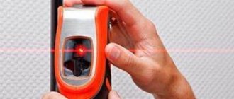
When working with such devices, certain rules must be followed. Thus, it is strictly unacceptable to direct the laser beam towards a person. Getting it into the eyes can lead to irreparable consequences, including loss of vision.
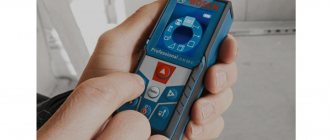
Taking measurements in bright sunlight can be difficult because the laser marker may be difficult to see. In this case, it is necessary to use special glasses through which it will be immediately visible.
Laser photography on location
When taking measurements outdoors, especially over long distances, it is necessary to use a plate called a visor.
Additional functions
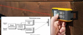
The microelectronics used in laser rangefinders allows not only direct measurements. Many devices of this type have some additional functions, which include:
- Continuous measurement function. When operating in normal mode, the rangefinder, when you press a button on the remote control, records the result and displays it on the monitor. But quite often, there is a need to constantly measure the distance, for example, from a wall to a future partition. To do this, the device is switched to continuous measurement mode. In this mode of operation, the device independently takes measurements at a certain frequency and displays their results on the monitor. The measurement takes place in real time.
- Determination of the greatest and smallest distance. This function is useful when determining the diagonal in a room. The fact is that it is not so easy to measure it and you can simply miss when directing the laser beam and, as a result, inaccurate results will be obtained. After setting the minimum distance on the device, it will record only those measurements that are greater than the set one.
Post scriptum
If you found the article useful and informative, you can kindly support the project by making a contribution to its development. If you didn’t like the article, but you have thoughts on how to make it better, your criticism will be accepted with no less gratitude.
Please remember that this article is subject to copyright. Reprinting and quoting are permissible provided there is a valid link to the source, and the text used must not be distorted or modified in any way.
Source
Components used
Parts List:
1 x Arduino NANO 1 x Module with VL53L0X sensor 1 x Boost converter 1 x Stepper motor 1 x Stepper motor driver on A4988 chip 1 x Slip ring for 6 wires. Diameter 12.5mm, length 15mm or less 1 x 6710ZZ bearing 1 x Hall sensor 49E 1 x Development board 1 x 100uF electrolytic capacitor 1 x 5mm x 1mm neodymium magnet
You will also need a 10K resistor, some M3 screws, nuts, insert nuts, a bezel and a 3D printed case, solder and a soldering iron.
3D printable files can be downloaded from the following link. PLA plastic was used for printing. Instead of a steel bearing, you can use a printed one (steel balls are sold in bags, for example, as spare ones for linear guides). You can draw a model for printing yourself or try searching on the website Thingiverse, Cults, etc., for example, by entering “parametric bearing” into the search. Instead of a bearing, you can simply print a plastic ring, for example, made of PLA, PETG, nylon or PET. If the plastic you are using does not slide enough or you are worried that it will wear out over time due to friction, you can stick adhesive tape or a ring of some material on top and bottom (films for lamination, films for laser printing, packaging for felt-tip pens, thin-walled boxes, etc.) .d.).
A boost stabilizer is needed for a stepper motor. Such motors usually consume a maximum of hundreds of milliamps. It is advisable to take a stabilizer with a reserve, say 1A or more. The output supply voltage of the stabilizer is 12V or more. When choosing a stabilizer, also keep in mind that they should not be too large, otherwise it cannot be placed inside the case.
Translator's afterword
One cannot help but pay tribute to the author’s ingenuity, although the literary side of the article, of course, leaves much to be desired.
It is not entirely clear to me how changing pupil size can affect the distance between the pupils. Obviously, the author does not mean the distance between the centers of the pupils, but rather the distance between their medial edges. In my opinion this is not entirely correct. In the end, the optical axis of the eye passes through the center of the pupil, and therefore for our purposes it is the distance between the centers of the pupils that is important, which does not depend on their diameter. True, when the pupil dilates (mydriasis), the depth of sharply imaged space decreases, as a result of which out-of-focus objects (including the double triangle of the rangefinder) will look somewhat blurrier. This slightly reduces the accuracy of the measurement, but not so much that this fact is worth paying special attention to.
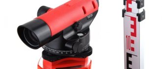
| Fig.4 This is what a metric rangefinder looks like. |
The precision of rangefinder calibration empirically, i.e. literally by eye, also raises certain doubts in me. The measurement method is too inaccurate (especially for long distances) to be used when marking a reference scale. In my opinion, it is better to calculate the location of the horizontal marks on the rangefinder scale. I even came up with an algorithm that can make this task easier. All you need is to ask someone to measure the distance between the centers of your pupils (with your eyes looking into the distance), as well as the distance from the eyes to the rangefinder scale held at arm's length, then insert the resulting numbers into the appropriate cells of the form and press Click the “Build table” button. For each distance, you will receive the height of the corresponding horizontal mark, counting from the base of the triangle, as well as its length (segment CD in Figure 3). All measurements are, of course, metric.
Rangefinder scale calculation
With this data, you can easily mark your own rangefinder.
To measure the length of your arm, you can use a tape measure, and to determine the interpupillary distance, you can use a phoropter or, at worst, a regular ruler. It is strictly undesirable to use a marking compass.
Thank you for your attention!