Checking the inclination of the entire plane of the laser level relative to the horizon
For those who have just started using a laser level or are just planning to purchase one, we recommend that you familiarize yourself with the general errors found in laser levels.
We install the laser level exactly in the middle between two walls located approximately 5 meters from each other. Turn on the laser level and mark the point indicated by the laser cross on the wall. We rotate the laser plane builder 180 degrees and mark a point on the opposite wall, placing the point at the intersection of the vertical and horizontal planes.
Next, we move the laser level to one of the walls and install it at a distance of 0.6 - 0.7 meters from the wall, and make the same marks on the walls by analogy as described above.
We measure the distance between points a1 and a2, also between currents b1 and b2. We subtract the resulting distance from the other (a1 and a2) - (b1 and b2), compare the resulting value with the declared accuracy, if the resulting value does not exceed the stated accuracy in the instructions, then your laser level shows the horizontal plane correctly.
Example: When checking the accuracy of a laser plane plotter, the distance between the points was: (a1 and a2) = 4 mm, and (b1 and b2) = 6 mm. Thus, the resulting error of the laser level is: (b1 and b2) – (a1 and a2) = 6 – 4 = 2 mm. We compare the resulting error with the error declared by the manufacturer.
This applies to laser levels that do not have a 360 degree horizon.
To check the horizontal plane of levels with cone prisms, such as Hilda 3D, or levels with cylindrical prisms, but also having a horizon of 360 degrees, such as ADA 6D Servoliner, the easiest way is to pass all sides of the horizontal plane through a point at a distance of 5 - 10 meters. Here you should also remember how the error is calculated correctly.
Horizontal line of sight and its verification
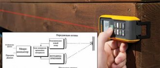
Checking the cylindrical level. Measurements with unequal distances to the slats.
To set it up, the following condition must be met: the pointing line of the device must be horizontal when the bubble is in the central part of the zero point. To check whether this condition is met, you need to select 2 points (C and M), which are separated by 25-35 m. The slats are installed in them, and the level is fixed on a tripod so that it is in the middle, between these points. The device is activated and a reading is taken along the slats, and then the difference between the levels of the points (C and M) is calculated. As an example, let’s say that the level reading on the first reading is 1.378 meters, and on the second reading – 1.278 meters. Then the excess (PRSh) is equal to the difference of these numbers - 0.1. Rearrange the tripod with the level as close as possible to point C and take a new reading on the staff. Let’s say it is 1.2 m. Then the theoretical indicator is: at the first point – S-PRSh = 1.278, and at the second staff – M-1.2 = 0.078 meters. Then they take a new reading on M and compare the resulting figure with the theoretical one. If this difference is more than three millimeters, then adjustment must be made.
Cylindrical level and slopes at the position of the bubble: a - side view, 6 - top view, 1 - ampoule, 2 - liquid, 3 - bubble, 4 - correction screw, 5 - ampoule slope.
Unscrew the protective cap on the eyepiece, using the adjustment pin supplied with the level, turn the set screw until the actual reading on the middle horizontal line coincides with the theoretical result (0.078 meters). Then the test is repeated.
If you install the level in such a way that the eyepiece of the tube, with the sighting axis positioned horizontally, is two to three centimeters ahead of the staff, then you can very accurately determine the height of the instrument from it. You need to put a cardboard or plastic cover painted black on the lens. In its center you need to make a hole of two to three millimeters. The main observer looks through it at the rail, and the assistant installs a movable part made of transparent material with a black line in the middle on it. According to the instructions of the observer, it is installed so that the mark is exactly opposite the hole in the cover. After this, a countdown is made along the staff.
Checking the straightness of the horizontal laser level beam
We install the laser level at a distance of approximately 5 meters from the wall and mark the point at the intersection of the vertical and horizontal beam.
Without changing the location of the laser level, we turn it 2.5 meters to the right (that is, we shift the vertical line from the marked point by about 2.5 meters to the side) and look at the left tail of the horizontal beam, if the beam is relative to our point within the error, then The laser level is configured correctly.
We repeat the same action, only we turn the device to the left 2.5 meters and check the right tail. Attention: do not shift the rotation axis when checking accuracy.
Checking the right angle of the 3D laser level
In conclusion, you need to check the right angle, which is constructed by two lines. This must be done without fail and not skip the third stage.
Initially, we return the level to the rotary base, this will make it easier to work. We do not recommend using squares, fastened rules and other improvised means to check the right angle. Here we will need knowledge from the school course about the Egyptian triangle. To do this, the easiest way is to draw it on the floor, and put two marks on each leg - at the beginning and at the end. We put the level at the beginning and, using the settings and the rotating mechanism, combine the rays with our marks on the legs. Let's look further: the rays must coincide with the distant marks with a very small error, otherwise the constructed angle will not be straight at all.
Checking the vertical plane accuracy of a laser level
We install the laser level about 5 meters from the wall and attach a plumb line about 2.5 meters long to the wall. We turn on the laser level and draw a line with a rope plumb line; if the deviation of the vertical line (above or below) does not exceed half the value of the “accuracy” characteristic, for example, +/- 3mm at 10m, then the accuracy of the line is within acceptable limits.
If, when checking the accuracy of the laser level, an error is found that is beyond the permissible limit, contact the service center, or carry out the adjustment yourself.
Plane plotters with cone prisms, such as the Huepar 902CG, can be tested using the same technology.
What you need for verification
It is recommended to carry out verification in a room whose diagonal is at least 5 m. This requirement is due to the fact that with smaller room sizes it is not possible to detect the presence of an error within the range of 1.0-1.6 mm. Considering the possibility of using the level in rooms of different sizes, the requirement for room area should not be neglected. There are no special requirements regarding the height of the room where the inspection is carried out.
During operation, the tool must be placed on a flat surface (table or stool). Do not use additional mounting devices (rod or tripod).
You also cannot do without a lined sheet with thin lines. When projecting a laser onto the surface of a wall in a room, drawing a line with a pencil does not provide accurate data on the distance between the lines. This will make it more difficult to detect errors. A lined sheet of paper is better suited for this.
Deflection of the laser beam during leveling can occur when the temperature in the room changes from the floor to the ceiling. To avoid this, it is recommended to install the instrument on a table or chair at least 20 cm high.
Avoid dropping or hitting the device. This may also affect the accuracy of the measurements.
Compliance with these rules will help to achieve the most accurate results when working at this type of level.
Checking the 90 degree angle between vertical planes
Depending on the design of the laser level, monitoring this parameter can be divided into two techniques.
First technique
If your laser plane builder is made in the shape of a barrel and has a rotating base - a tribrach, for example, a Firecore FIR411G level, then checking the angle for compliance with the declared value between the verticals is very simple.
To do this, we install the device in the middle of the room, preferably at a distance of at least 2 meters from the walls, and make marks on the vertical lines running along the walls.
After that, without moving the device in any way, we turn the “head” of the level clockwise 90 degrees and align the verticals with the marks made earlier. If you have four vertical planes, then we drive all the verticals through the given points.
As a result, if during turns all verticals were aligned with points with an acceptable error, then the angle between them was 90 degrees. If, when rotating around its axis, one line passes through a point, and the second has a strong deviation, then the 90-degree angle is not accurately adjusted.
Second technique
Laser levels with cone prisms of the Fukuda MW-93T-3GJ type have a displaced central axis, so the first test method is not suitable here, since when turning the lines will definitely run away from the marks.
To check this indicator, we install the device on the floor and make two marks on the verticals running along the floor, the first point is closer to the body, the second at a distance of about 2 meters. Or we make one point on the floor, at the crosshairs of two verticals, and mark two points along the walls on vertical lines running at an angle of 90 degrees relative to each other.
Next, turn the body of the level 90 degrees and align the lines with the marks. We repeat the procedure until we check all four planes.
You can watch these methods in more detail in the videos below.
How to check a level for vertical accuracy?
The question of how to check a laser level along the Y axis is absolutely identical to checking it along the X axis with only one correction - working in a vertical plane with distances of several tens of meters is in most cases extremely inconvenient. Therefore, to check the vertical projection of the level, it should be rotated 90 degrees relative to the position in which you checked the horizontal beam. After this, all measurements are carried out in the same order, and as a result you should also get a deviation less than the accuracy specified by the manufacturer.
Investigation of the correct operation of the cylindrical level
If a cylindrical type level is used on the telescope on the model of the device, then it must satisfy the following conditions - its axis must be strictly parallel to the line of sight of the telescope. This check must be done in two stages:
- the plumb plane passing through the main axis of the cylindrical level must be parallel to a similar surface passing through the line of sight of the telescope;
- the projection onto the vertical plane of the angle between the axis of the level and the pipe should not exceed the limit established in the passport.
The first condition is checked using a rod installed 45-55 meters from the tripod, the lifting screw of which is directed in its direction. Carefully check the horizontal position of the device, use the lifting screw to align the ends of the level bubble, and use the fixing mechanism to obtain a clear image. They count down. Then the axis of the device is tilted using lifting screws so that the readings do not change, and the position of the ends of the cylindrical level is fixed. The same is done when tilting in the opposite direction. If the bubble remains in place in both cases or its ends move in the same direction, then the level setting is considered correct. If this is not the case, then adjustment is made with horizontal and vertical screws of the cylindrical level itself.
The second condition is checked using methods such as:
- leveling in a straight forward direction;
- the same, but in combination with measurements from the middle;
- application of the method using different arms.
With each method, and they are described in the specialized literature, at least 3 measurements of the angle between the level axis and the projection onto a vertical plane must be carried out. Then the arithmetic mean of these measurements is calculated and compared with the passport data. If the resulting figure does not exceed the permissible limits specified in the document, then the level is configured correctly.
DIY laser level repair
The level may be subject to shaking and falling. This affects the accuracy of the work. A large error appears or the laser beam disappears completely. You can disassemble the device yourself and inspect it for visible defects. If there are none, make adjustments.
Remove the batteries or battery. Unscrew the mounting bolts. Carefully separate the housing parts.
The level wiring is very thin
Shift all planes to the left
Horizontal line shifted
Hexagons and holes for adjustment
Arc instead of line
Adjustment screws for arc formation