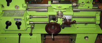
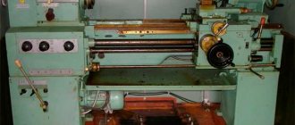
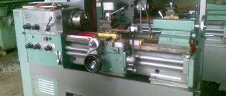
The cam lathe chuck is a necessary component for a lathe. The final result of the work depends on the quality of the clamping device. In particular, if the chuck does not provide the greatest clamping force, the part may simply fly off the front end of the spindle. The device is responsible for the accuracy of centering and influences whether the processing axis will be exactly perpendicular to it. Of course, the issue of choosing a component should be taken very seriously, since it determines the effectiveness of the procedure and the quality of the resulting parts.
General concepts about lathe chucks
Lathe chucks are selected depending on the technical characteristics of the device and the spindle, in particular. They represent the main components of the equipment. The mechanism is a cam effect. Dimensions are selected depending on the parameters of the unique workpiece.
The cams ensure reliable fixation of the mechanism. Due to the action of mechanical force, which determines the tightness of the fastening, installation and fastening occurs. The workpiece is fixed using a chuck.
It should be taken into account that the parts that need to be processed have different sizes and diameters.
A low-quality cartridge will not hold as tightly as possible; as a result of strong mechanical movement, it can fly off, and the workpiece with it. The chuck ensures smooth movement of the fastener, while the workpiece will not move relative to the center. In the simplest sense of the word, a chuck is a mechanism that is responsible for rotating the workpiece, making its processing efficient and smooth.
Specifications.
The chuck body is made of high quality special cast iron
Table 1
| Name of parameters | Values |
| Outer diameter D, mm | 250 |
| Diameter of connecting belt D2, mm | 200H7 |
| Diameter of hole in housing D1, mm | 76 |
| Diameter of mounting holes, mm, D3 | 224 |
| Outer diameter of the product clamped in straight jaws, largest mm | 120 |
| Outer diameter of the product clamped in the return jaws, largest mm | 266 |
| Maximum permissible rotation speed, min ' | 2000 |
| Flange side height | 5 |
| Chuck height without jaws | 85 |
| Height of chuck assembly | 119 |
| Cartridge weight, kg | 29 |
| Fasteners | 6 M12 bolts |
Using a lathe chuck, using straight and reverse jaws, you can clamp workpieces in the following range of sizes
The straight cam is designed to secure the workpiece to the outer surface of the shaft or to the inner surface of the hole in the workpiece. The reverse cam is designed to secure the workpiece to the outer surface.
Accuracy characteristics of lathe chuck
Fig.2.1 - Lathe chuck at idle speed
the cartridge provides the following accuracy characteristics: Radial runout a – 0.045 mm;
End runout c – 0.025mm.
By securing the workpiece in the chuck, the following characteristics can be achieved:
Scheme I:
range of fixed workpieces from 5 to 118mm;
Radial runout a at a length of 80 mm is 0.040 mm.
Scheme II:
range of fixed workpieces from 77 to 188 mm and from 160 to 250 mm;
Radial runout a – 0.045mm;
End runout c – 0.025mm.
Scheme III:
Purpose
Inside the type of part in question is a cam mechanism. This important component allows you to center and clamp the workpiece. This happens due to the narrowing of the cam parts, and then clamping them with a quill. Only after the part has been completely secured can you begin working on a wood or metal lathe. If the procedure is not followed, the workpiece may not only fall out or be damaged, but also cause harm to the master.
You should carefully check the quality of fastening of the part in the chuck. First, specialists turn on the lathe at low power and see if the mechanism rotates well. If after a few laps everything is in order, they will continue to work at higher powers.
Overview of species
Different spray-coated tools can vary significantly in performance, despite the fact that they are all used for metal work. Some are needed for roughing, others for finishing sanding or filing small parts. According to GOST 1513-67, needle files must be marked indicating the main parameters. Tools can be divided into groups according to a number of characteristics.
By shape
The type of profile indicates for what purpose a particular file is suitable. Acceptable forms are established by the state standard. There are quite a lot of them, which allows you to choose tools for different stages of work.
Flat, with a blunt nose:
- have a rectangular shape;
- have 4 edges, 2 of which are wide and the rest are narrow;
- Suitable for both processing flat surfaces and cutting grooves and other hard-to-reach places.
There are also flat needle files with a sharp nose. They are distinguished by a different shape of the tip of the working part, otherwise they have the same features as obtuse-angled products.
Rhombic:
- upper corners – blunt;
- there are diamond-shaped edges;
- scope of application – processing of parts with different angles.
Square products are needed for filing rectangular grooves. All edges of the tool are working.
Triangular files come in two types:
- pointed - suitable for processing external grooves in small parts, all edges are involved in the work;
- obtuse-angled - they can have either one working side or all three; the latter option is more popular.
Round instruments usually have a sharp tip. They are suitable for turning relief elements. Similar in shape are oval models; they can be used to process round parts.
To size
Product parameters are usually indicated in the labeling. It can contain three numbers, for example, one of the popular sizes 140x70x3, where 140 mm is the length of the product, and 70x3 mm is its cross-section. Files with parameters 140x50x3 are also in demand. For some shapes, the section is indicated by one number, for example, a 4 mm round needle file.
The length of the products may vary, but the most commonly used tools are 80 mm, 120 mm, 160 mm. If necessary, you can purchase a file from 100 mm to 450 mm for work.
By grain level
Depending on the purpose, the coating of the file may vary
It is worth paying attention to the density of the grains. If there are few of them, then after processing the product will be rough, but with a fine-grained file you can make the surface smooth. For convenience, color markings are applied to the handle of the instruments:
For convenience, color markings are applied to the handle of the instruments:
- red – grain density ranges from 160 to 80 units;
- blue – grain size ranging from 80 to 55;
- if there are no markings, then the coating may have 50-28 grains per 1 cm2.
Classification of lathe chucks
There are several types of classifications: according to the number of cams, type of clamp, fixation mechanism, type of execution, accuracy class.
By the number of jaws in the chuck
Cams are responsible for the quality of fastening of parts. They are made of high quality metal.
Double cam
Options secure asymmetrical parts that are not processed. But they are also used for standardized workpieces.
Three-jaw
Optimal for producing hexagonal and round variations. Shunting occurs on three sides of the cams.
Four-jaw
The 4 jaw chuck consists of four units that function independently. Used for processing rectangular and square options.
By type of workpiece clamp
The chuck jaws are divided into direct and reverse. Virtually no effect on performance. Selected depending on the type of cartridge input.
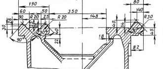
Device and principle of operation.
3.1. The design of a spiral rack lathe chuck is shown in Fig. 3.
Fig. 3 - Design of a spiral rack lathe chuck.
Cams 1, 2 and 3 of the cartridge move simultaneously using disk 4. On one side of this disk there are grooves (shaped like an Archimedean spiral) in which the lower projections of the cams are located, and on the other there is a cut bevel gear mated to three bevel gears 5. When you turn one of the wheels 5 with a key, disk 4 (thanks to gearing) also turns and, by means of a spiral, simultaneously and evenly moves all three cams along the grooves of the cartridge body 6. Depending on the direction of rotation of the disk, the cams move closer to the center of the chuck or move away from it, clamping or releasing the part. The cams are made in three stages and are hardened to increase wear resistance.
By type of execution
In the Russian Federation, the types of cartridges by design are regulated by GOST 2675 - 80.
Whole
Made from a piece of steel with parameters starting from 500 MPa. The most common type.
Made
A rail is made of steel, and a cam is attached to it. The latter is made of metal.
Overhead
Composite variations consist of non-ferrous metal, stainless steel, ferrous metals. Used for working with large-scale projects.
How to choose cutters yourself?
Wood cutters are a must-have tool for woodworking. You can make them yourself or buy them in a store. Wood cutters have the same design, although different shapes.
The following tools are the most popular among wood cutters:
- A universal knife-jamb, which is shaped like a triangular shoe knife.
- Clukarza is a chisel-like tool with a curved blade.
- A spoon cutter is a ring-shaped cutter that is used for cutting out dishes with deep recesses.
- Chisel, the most common type of wood cutter.
Chisels, on the other hand, come in all sorts of shapes to perform a variety of tasks.
Cutters for manual turning of wood are divided into the following types:
- Semicircular.
- Flat obliques.
- Cut-off.
- Cut-off with figured sharpening.
- Angular.
- Shaped.
- Hook cutter.
- Ring cutter.
- Beveled corner.
Special ones can consist of two metal plates that can be moved relative to each other, so that a unique cut or pattern can be obtained. The most popular cutters for turning work are:
- Reuter is a tool with a semicircular cutting tip.
- Meisel is a tool with a beveled flat blade.
It is used for processing wood and bringing it to the state of a finished product.
Cartridge accuracy classes
The accuracy of the device is determined in GOST 1654 86. There are four stages in total.
Class H
Normal indicators, averaged.
Class P
Higher class, used for making hard production parts.
Class B
High accuracy - used for processing small variations.
Class A
Particularly high accuracy. Scope of application: small and hard workpieces.
Dimensions
The common dimensions for direct and reverse cams are:
- the presence of identical sizes in terms of basic parameters - length, width, height, comb pitch, step sizes, etc.;
- are unified in their design, however, the set of jaws of one cartridge is not identical to the set of another (substantial modification is always required);
- cams with dimensional errors do not fasten the part correctly. At the same time, one of them does not participate in the clamping, forming a gap between the prism and the surface of the part, which is easily checked with a flashlight beam;
- wear on the surfaces of the disk spiral and the cams and racks significantly changes the characteristics of the clamping forces and the accuracy of the rotation part;
- inaccuracy in the linear dimensions of contact surfaces, for example, slats and pads, leads to displacement of the working surfaces, and hence, either excessive clamping forces or their absence at all, which is unacceptable and dangerous when working with such devices.
Self-assembly of the cartridge according to the drawings
Self-assembly does not take much time. This is a fairly simple process. The main thing is to understand the mechanism of operation of the device. As a last resort, you can order such miniature equipment from a professional turner. He will assemble any variation from the available parts. Homemade models cost significantly less than those ordered from production.
The quality may be even better than factory ones.
Installation of the mandrel
The frame is put on first. Installing the part makes it possible to secure the cartridge.
Installing the chuck itself on the spindle
The mechanism is being secured. Do not press or bore parts. At this stage, fastening occurs with previously prepared bolts of suitable size.
Consolidation
After checking the quality of the wrapping, the final assembly of the mechanism is carried out. The bolts are screwed using a wrench.
Securing the workpiece
Tools are installed on a homemade cartridge. Carried out after checking the assembly with bolts.
Releasing the cartridge
Once the workpiece is screwed in, the frame is no longer needed. It is carefully removed.
It is imperative to check the functionality of the self-made mechanism. The product is placed in a lathe. Several smooth turns are made and the clarity of the fastening is checked. The specialist assesses the level of centralization and whether objects move.
Homemade cartridges must be periodically serviced. They are completely disassembled, the inside is cleaned, and then dried in the fresh air. Lubricated with regular oil. If the product is going to be stored, then this must be done according to the rules. Bend the fists into the central part, plug the hole tightly with a rag.
Such storage will ensure the integrity of the cartridge, since it cannot be damaged mechanically, and dust will not settle in the hole in the equipment structure. Before use, the old cartridge is lubricated and runs for up to 10 minutes at a smooth, slow speed.
File manufacturing technology
In Russia, two groups of tool steels are used for the production of files: unalloyed improved steels with a carbon content of 1 to 1.3% (YUA - U13A) or alloyed chromium steels ШХ15 or 13Х.
Similar steels are used by file manufacturers abroad. Carbon content of one percent and above allows the notch to be hardened to high hardness. The technology for producing files may differ significantly in detail from one production to another, but it always contains the following stages:
- Shaping processing;
- Formation of notches on working surfaces;
- Heat treatment.
The last two operations are especially important. The effectiveness of the file depends on how well the notch is made. When using worn-out equipment and tools, you can get a file that looks “just like a real one,” but in which, say, no more than 30% of the cuts work.
The service life of the file depends on the quality of the heat treatment.
The distribution of hardness and viscosity along the depth of the file body is very important here. Hardness should be maximum on the surface and gradually decrease in depth, viscosity - vice versa. Low hardness leads to rapid dulling of the notch teeth, and low viscosity (i.e.
high fragility) – to their rapid destruction during operation
Low hardness leads to rapid dulling of the notch teeth, and low viscosity (i.e., high fragility) leads to their rapid destruction during operation.
Most manufacturers regulate the nominal surface hardness of files depending on their purpose as follows:
- Bench files: 64 to 66 HRc.
- Sharpening files: 65 to 67 HRc.
- Rasps: 53 to 56 HRc.
The quality of a file can only be fully checked during its operation. The quality of files (both efficiency and service life) is especially important for industries in which manual filing is part of the technological process. There are still many like this. This is the production of some types of hand tools, forestry, where chain saws are used, which require periodic sharpening of cutting chains, and many others. When using files in production, it is necessary to constantly monitor their efficiency and service life, since experience shows that almost any file manufacturer can have defective files.
The length of a file always refers to the length of its working part (the entire part, not just the cut part), without the shank. The exception is needle files. For them, the total length is always indicated, including the shank (if any).
In metric countries, the following range of sizes (in mm) are used: 100, 125,150, 200, 250, 300, 350 and 400.
Most manufacturers use only part of the denominations from this series.
Grinding
First, let's make sure that the cams really need grinding. Let's take a metal shaft and place part of it in a lathe chuck. Clamp the shaft with cams. During operation, you may notice that the cams are hitting the part. Therefore, they need care.
The inner plane of the cams is subjected to grinding. First you need to clamp the ring with your fists so that they do not unwind spontaneously. It is believed that the simplest method is grinding using a cutter with a special stone.
We install the frame with the stone on the cutter, turn on the lathe chuck and move the part with the stone along the plane of the cams. Due to rotation and contact with the stone, their surface will acquire the desired characteristics.