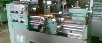
The IT-1M model lathe is specialized turning equipment designed for mobile automobile workshops of the Ministry of Defense, housed in standard KUNGs. The dimensions of its working space are almost the same as those of the most popular Soviet lathe 16K20. At the same time, its weight is almost three times less, and the power of the main engine is only 3 kW (versus 11 kW for the 16K20).
The machine can be powered either from a 220 V or 380 V network, or from an autonomous generator. IT-1M is the best model for “garage use”, because can process parts of the same size as industrial lathes, but is powered from a household electrical outlet. In addition to the mobile version, a stationary version of this lathe was also produced, which is designated IT-1GM.
Specifications
IT-1M is a standard screw-cutting lathe and can perform all types of processing typical for equipment of this type.
Its main feature is the low power of the main drive with a significant working space.
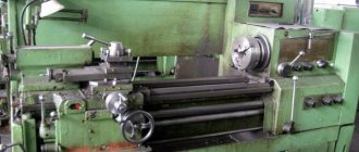
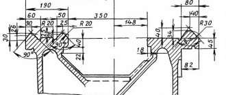
With a light weight for its class, the IT-1M lathe has good rigidity and vibration resistance. He owes this to the successful design of the frame - a hollow cast base with partitions and stiffeners. Another advantage of IT-1M is the ability to increase the turning diameter to 550 mm. For this purpose, a recess with an insert is provided in the bed, which is removed when turning large workpieces.
The technical parameters of the machine are quite sufficient for work in the machining departments of small enterprises. The maximum turning diameters for products in the form of a shaft and disk depend on the dimensions of the workpiece and are above:
- bed – 400 mm;
- recess – 550 mm;
- caliper – 225 mm.
The maximum processing length on IT-1M is 1400 mm (with a remote insert - 300 mm), the diameter of the spindle through hole is 36 mm. The scale division on the caliper controls is 50 microns, and the rotary scale is 1°.
If you need to install plastic windows, insulate a balcony or loggia, we recommend contacting the Window Master company. You can learn more about their services on the official website: https://okonniymaster.ru/balcons/vnutrennyaya-otdelka-balkona.html. You can not only insulate the balcony, but also cover its floor with plywood, linoleum, parquet or laminate. For wall decoration, lining, plastic PVC panels, decorative plaster, cork or decorative stone are used.
The IT-1M lathe was produced in two modifications: basic and shortened. In the first case, the center-to-center distance of the headstocks is 1400 mm, and in the second - 1000 mm. The basic version weighs 1.33 tons, the shortened version is 190 kg lighter: its weight is 1.14 tons.
Areas of application of machines
The unusual relationship between the geometry of the working space and the power of the main drive of the IT-1M lathe is explained by the fact that it was initially developed according to the technical specifications of the Ministry of Defense as standard equipment for field auto repair units of the Soviet Army.
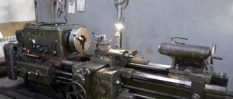
The army mobile auto repair shop (PARM) included several units of special equipment, including the MRM-M1 (mechanical repair workshop) based on the ZIL-131. It was a KUNG, which housed an electric power plant and several machines: a screw-cutting lathe, a drilling machine, a sharpening machine, and a sharpening and grinding machine.
Design features
The IT-1M screw-cutting lathe has the usual layout for this type of equipment: a bed with guides, headstock and tailstock, and a support with cutting slides. Among its features are an insert into the bed, the removal of which allows you to process larger workpieces, as well as the low power of the main engine, which makes it impossible to turn with large cutting depths. The machine's passport indicates that it can be used to mount devices for milling planes and grooves, as well as performing boring and grinding operations.
Overall dimensions of the workspace
The processing geometry of IT-1M is almost the same as that of the most common screw-cutting lathes 1K62 and 16K20. It allows you to turn shaft-shaped parts with a length of up to 1400 mm and a diameter of up to 225 mm and disc-shaped parts with a maximum diameter of 400 mm (with the insert removed - up to 550 mm). The shortened version of this model has a maximum workpiece length of 1000 mm.
Location and operation of controls
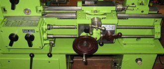
Most of the controls of the IT-1M lathe are mounted on its front headstock. On its upper part there is a panel with toggle switches (from left to right): voltage selection switch, cooling motor switch and circuit breaker, and in the lower part there is a spindle speed selection lever. Above it there are three knobs in a row, through which the feed amount, type and pitch of the thread are set, and to the right of it is the spindle rotation control lever (on, reverse and braking). Under the toggle switch panel there is a thread type selection knob and a selection knob.
The following controls are mounted on the apron: caliper positioning handwheel, carriage and cross slide positioning handle and running nut handle. Above the handwheel is a handle for transverse movement of the carriage, and above it is a lever for turning and fixing the tool holder. The tailstock controls are few: the steering wheel for moving the quill and the lever for its clamping. In addition, there is also a nut that secures the position of the tailstock.
Location of components
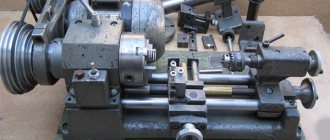
Like any lathe, the basic component of the IT-1M is a bed with two rows of guides. On the left is a headstock with a spindle assembly and gear mechanisms, and on the right is a tailstock with a quill. A caliper with longitudinal and transverse slides and a four-position tool holder moves along the guides.
IT-1M machine design
Although the equipment is a lightweight version, it looks very massive. On the right side there is a cabinet responsible for two functions: reliable support and placement of the cooling pump. There are also two pipes, one of which is responsible for draining, and through the second the excess goes away. The system lubrication device includes 4 units:
- oil reservoir;
- liquid supply pump;
- filter;
- Magnetic type cartridge.
The functionality of the lubrication mechanism depends on the rotation of the gearbox, and it can rotate in any direction. And everything is located on the left side of the device, under the feedbox and behind the engine.
This lathe and screw cutter is driven by a gear box, and adjustment is carried out by two levers on the front side. The support consists of an upper carriage, a slide for various movements and a mechanism for fixing the cutter. Rotation and fixation also occur due to manipulations with the handles.
On top there are two guides that have undergone heat treatment and grinding. Thanks to this, the machine's tailstock and carriage can move smoothly, providing maximum comfort while working. On the left cabinet (above the spindle control handles) you can see three toggle switches, which are responsible for the following functions:
- Far right - adjusts the feed amounts and turns off the box.
- Central - establishes a standard thread and performs feeding.
- Far left – adjusts the thread pitch.
At the top there is a table with symbols, and in the center there are two flywheels (the lower one provides the longitudinal movement of the caliper, and the upper one moves the carriage).
This device is equipped with PVG wires, the cross-section of which is 2.5 square meters. mm. They are designed for transmitting electricity in stationary installations. They should be located in places where there is no danger of mechanical damage, and the ambient temperature should be from -50 to +50 degrees.
These and many other characteristics show that IT-1M is a reliable lathe that combines reliability, safety and ease of use. It can also be used to perform a lot of technical tasks.
Electrical diagram
On the IT-1M lathe, three-phase voltages of 380 V and 220 V are used to power the electric motors. The signal and lighting circuits are powered from the on-board 12 V network.
The electrical equipment of the machine includes the following components:
- main electric motor;
- circuit breaker;
- main engine reverse switch;
- main engine voltage packet switch;
- batch switch of engine voltage of the coolant system;
- coolant system electric motor;
- coolant pump switch.
In addition, a lighting lamp on a flexible stand with a switch is installed on the machine support.
Design
Controls.
To fully present the unit’s control elements and their location, we will analyze them below. So, 39 parts will be presented to your attention:
- Handles for switching spindle rotational frequencies. Located on the body of the left cabinet.
- Handle for setting feed values, turning off the box. It is located on the body of the left cabinet below the spindle box.
- Handle for establishing standard threads (pitch, metric, modular, inch), as well as for feeding. It is located on the body of the left cabinet, below the spindle.
- Handle for setting thread pitch and feed. It is also located below the spindle box.
- Thread designation plate. It is located in the same place as the thread control handles.
- Handle for selecting the thread pitch (increased pitch, standard). Located on the front headstock.
- Handle for selecting thread direction (left, right). Location: left headstock.
- Handle for switching spindle head rotation speeds. Located on the front headstock.
- Designation plate.
- Voltage selection switch. Located on the control panel.
- Control panel designation plate.
- Voltage setting switch. Located on the control panel.
- Toggle switch to turn off or turn on the cooling engine. Location on the control panel.
- The toggle switch is automatic. Located on the control panel.
- Screw for clamping the housing to protect the jaw chuck. Located on the casing.
- Toggle switch to turn off the lighting. Located directly on the lighting lamp.
- Screw for clamping the rod with the screen. Located at the bottom of the screen itself.
- Handle for clamping and turning the tool holder. Located on a movable support.
- Nozzle for supplying the cooling element, which is adjustable. Location - support.
- Screw for fastening the cooling system tube. It is also located on the caliper.
- Handle for moving the carriage in the transverse direction. Located on the caliper.
- Handle for moving the upper carriage. Available on the caliper.
- The screw that secures the caliper.
- Handle for securing the quill. Located on the tailstock.
- Nut for clamping the tailstock on the bed itself. Located on the right (rear) headstock.
- Quill extension flywheel. It is located directly on the quill.
- The screw with which the tailstock moves in the transverse direction.
- Handle for mechanical movement of the cross slide and carriage. Available on the tailstock.
- Handle for turning on the nut located on the lead screw.
- A handle that includes rotation, reverse and spindle brake. Present on the tailstock.
- Handle for securing fittings related to lighting. It is located on the support, at the base of the fittings leading to the lighting lamp.
- Signal sign indicating whether the lead screw is on or off. Located on the caliper.
- A button that turns on the rack and pinion gear. Located behind the flywheel on the caliper.
- A flywheel that provides longitudinal movement of the caliper structure.
- The handle is responsible for reverse, brake, rotation of the spindle head. Located on the front headstock.
- High voltage warning sign. Available at the bottom of the left cabinet.
- A sign indicating the grounding location. Location: front cabinet, on the side.
- Stop button (stop button). Present on the control panel. As a rule, it is used on machines of the IT-1GM model.
- Signal lamp. Located on the control panel. Usually used on the IT-1GM model.
When all the details of the equipment are known to us, we can proceed to the electronics of the machine.
Kinematic diagram
The kinematic diagram of the lathe is similar to the diagrams of other universal screw-cutting lathes of medium size. The spindle receives rotation both directly from the driven pulley and from a system of switchable gears. The feed box receives movement from the spindle assembly through a system of replaceable gears and transmits rotation to the apron mechanism through the lead screw and the lead shaft.
The apron gear system imparts movement to the caliper, ensuring its transverse and longitudinal movement. The kinematic diagram of the machine also includes mechanisms for manual movement of its working parts and mechanical locking devices.
Main components
If we talk about the composition of this lathe, then it includes such main components as:
- cabinets;
- mechanisms to ensure cartridge obstruction;
- apron;
- gearbox;
- unit for providing lubrication;
- pasterns (back and front);
- a cabinet containing electrical equipment;
- gearbox;
- control Panel;
- bed;
- caliper
Caliper
Due to its overall dimensions (2160*1500*960 mm), the machine has the ability to work with parts up to 1400 mm in length.
User manual
The only documentation that came with the IT-1M lathe was a 66-page brochure called “Operating Manual.” The last chapter of this manual is the passport of a specific product indicating the delivery set, marks on acceptance, preservation and packaging, as well as signatures of the quality control department and the customer. It is noteworthy that the acceptance tests were carried out in a “van body of a mobile repair shop of the MRM type.”
In general, the operating instructions are quite traditional and contain general views, drawings of individual components, instructions for installation, configuration, commissioning and operation, as well as kinematic and electrical diagrams of the machine. The only thing that attracts attention is the lack of information about repair cycles and the scope of work for certain types of repairs.
Safety precautions
The operating manual for the IT-1M lathe contains section 2.1 “Safety Precautions”, which contains only two general sentences. They indicate the need for instruction and study of the operating manual before operating the machine.
Other instructions on safety precautions when operating the machine are included in separate sections of the first and second chapters. These include requirements for grounding, use of guards, testing of interlocking devices, chip protection, etc.
Safety precautions when working on the machine
The IT-1M metal lathe belongs to the high-risk category, so there are strict rules here:
- a person without qualifications is prohibited from working on such equipment;
- During all procedures, the correct position of the torso and arms should be observed;
- before starting actions, the master is required to provide instructions;
- there must be a fire extinguisher and other fire-fighting systems in the equipment room;
- If a malfunction of the unit is detected, you should immediately stop work and call a specialist;
- DIY repairs are strictly prohibited;
- the worker's eyes must be protected from metal shavings;
- It is forbidden to carry out manipulations with lowered sleeves.
This is just part of the rules that every employee must know. A more detailed version can be found in the full version of the safety and operating rules.