Mechanical (electromechanical) guillotine shears H3118 are industrial equipment designed for direct cutting of sheet or strip metal (steel, non-ferrous metal products or alloys). Mechanical (electromechanical) guillotine shears N3118 are made with a top drive. For measured cutting of strips, the guillotine of N3118 scissors is equipped with a back stop, which is installed on the back side of the knife beam. When cutting with a guillotine, the sheet is pressed by a pressure beam that works in concert with the knife beam. The necessary clamping conditions are provided by springs that are placed in the cups of the clamping beam. The electrical circuit ensures the operation of the scissors in single and automatic strokes. The control of the H3118 guillotine shears is push-button and pedal controlled. Combined lubrication of the main mechanisms.
Design features of guillotine shears N 3118
The scissors frame is welded and consists of two posts connected by corners. A table is mounted in the front part of the frame, which can be moved to adjust the gap between the knives.
The scissors are driven by an individual electric motor through a V-belt and single-stage gear transmission.
Scissor clutch with two rotary keys, band brake, intermittent action. The frequency of braking is achieved due to the eccentric location of the pulley relative to the axis of the crankshaft. This braking occurs when the knife beam is in the upper position, which prevents it from running under the influence of inertial forces.
The knife beam is balanced by a spring balancer. The force on the knife beam from the crankshaft is transmitted by two connecting rods.
The pressure beam presses the material being cut to the scissors table with its own weight and springs. The movement of the pressure beam is coordinated with the movement of the knife beam.
The scissors can operate on single and automatic strokes.
Push-button control from the remote control and from the foot pedal.
Lubrication of the main components is centralized.
For safe work on the scissors, a protective grid is provided.
Design of guillotine shears H3118
The shears consist of a frame, knife and pressure beams, drive, drive shafts, engagement clutch, back stop, balancer, brakes, guards, electrical and lubrication systems, and protective grille.
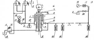
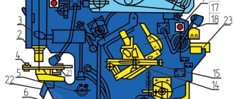
Bed (Fig. 10)
The bed is the base unit on which all other scissor units are attached. The frame is a welded structure consisting of two posts 1 and 3, connected by angles 2.
A table 4 rests on the racks, to which the lower knives 5 are attached with screws.
To adjust the gap between the table knives and the knife beam, the table can be moved with bolts 13, having first loosened bolts I and 12, which need to be tightened again after adjustment.
The height of the knife during resharpening is adjusted by adjusting the spacers 6.
There are 7 extensions on the table, with T-shaped slots for attaching stops.
On the left edge of the table there is an extension 8 fixed with pins, in the T-shaped groove of which a cross-cut stop 9 is attached; to carry out longitudinal cutting, this stop is removed.
The bed has guides to which textolite pads 10 are attached, along which the knife beam moves.
Drive, drive and crankshafts of guillotine shears Н3118 (Fig. 11 and 12)
Drive of guillotine shears H3118
Drive and crankshafts of guillotine shears H3118
The shears are driven from electric motor 1 through a V-belt transmission to flywheel 4 through gears 5 and 6 to crankshaft 7.
The electric motor is attached to the sub-motor plate 2, hinged on the frame. Belt tension is adjusted using nuts 3.
Clutch for turning on guillotine shears N3118 (Fig. 13)
Clutch for turning on guillotine shears H3118
At the left end of the crankshaft, a keyed engagement clutch is installed in the gear hub.
Bushings 1, 2 and 3 are stationary in the gear hub. The remaining parts are connected to the crankshaft. The rotating (working and locking) keys of the engagement clutch are activated by springs 6 and, turning, are captured by the semicircular grooves of the bushing 2. Bushings 8 and 9, having semicircular grooves, complement the sockets for the round ends of the key.
The right end of the working key is equipped with an easily detachable shank 4, which, hitting pin 2 (Fig. 17), disables the keys connected to each other by levers 5.
When turning the keys on and off, their angle of rotation is limited by the groove of the drive sleeve 7.
Knife beam and clamp (Fig. 14)
The knife beam is an L-shaped welded structure, reinforced with ribs 5.
Knives 6 and the back stop are attached to the knife beam with screws (see, Fig. 15).
The force on the knife beam from the crankshaft is transmitted through two connecting rods 7.
In the upper position, the beam is held by springs after lifting; during repairs, it is fixed in the upper position with a pin inserted into the Ø20 hole of the knife beam and the frame on the left side.
During operation of the scissors, the sheet being cut is pressed against the scissors table by a clamping beam 1, connected by projections 2 with the projections of the knife beam, due to which the clamping is carried out automatically and in coordination with the movement of the knife beam.
The pressing force of the clamp is regulated by springs 3, mounted in the cups on the clamping beam. A safety mesh 4 is welded at the bottom of the pressure beam.
Back stop (Fig. 15)
The back stop is installed on the back side of the knife beam and serves as a stop for the sheet during cross cutting.
The back stop consists of 2 cylindrical racks 1, which are moved manually by flywheels 2 sitting on the shafts of 3 gears meshed with the racks.
By moving the slats, the stop line is set at the required distance from the edge of the knife, which achieves measured cutting of the sheet using the back stop.
When the stop ruler is positioned as shown in Fig. 15, the back stop allows you to cut sheets up to 480 mm long.
To cut workpieces up to 900 mm in length, it is necessary to rearrange the stop ruler and secure it in additional M16 holes located on the slats.
Brake (Fig. 16)
An intermittent brake is mounted on the right end of the crankshaft. The frequency of braking is achieved due to the eccentric location of pulley 2 relative to the axis of the crankshaft 1. This braking occurs when the knife beam is in the upper position, which eliminates its running under the influence of inertial forces.
Electromagnetic control (Fig. 17)
To obtain single cuts, the PR switch is set to the “single stroke” position, the PU switch is placed in the “button” or pedal position. When you press a button or pedal, an electromagnet is turned on, the armature of which turns the fork with pin 2, releasing the shank 4 that engages with it (Fig. 13), connected to the working rotary key. After that, under the action of springs 6 (see Fig. 13), the keys turn and turn on the crankshaft. A single cut occurs.
If the operator does not release the button or pedal in the “single stroke” mode, blocking the 2K magnetic starter along circuit 102-117 (see electrical diagram) opens this circuit. The contactless limit switch screen turns off the 1RP relay. which, via circuit 29-33, turns off the 2K starter.
To repeat the working stroke, the button or pedal must be released. To carry out automatic moves, the PR switch is set to the “automatic move” position, and the PU switch is set to the “button” position. By pressing the 4KU button on the remote control, the 2K starter is set to self-power and the electromagnet is turned on. The machine operates in “automatic” mode.
The stop is made by the ZKU button.
Scissor guard (Fig. 18)
The shear guard is made of 1.6 mm thick sheet steel.
The guard consists of 3 casings, one of which covers the V-belt pulleys, the second covers the drive gears, and the third covers the shear brake.
The casings are fastened to the frame using M8 bolts.
Lubricant for guillotine shears H3118
The main rubbing surfaces are lubricated from a manual pumping station through feeders (see the installation and operation manual for the pump).
Drive gears and bearings are lubricated by applying grease to the gear teeth and bearing cups, respectively.
During operation, the scissors must be lubricated so that the grease comes out from the side locations of the bearings. The grease protruding from the gaps must be wiped off.
It is necessary to periodically check the condition of the oil nipples and oil-conducting holes in the parts and be sure to clean them.
At least once every three months, flush the lubrication holes with clean kerosene.
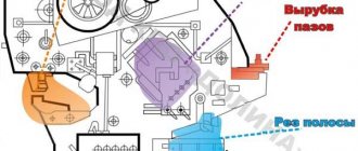
Guillotine for baguette
There are smaller devices that are used to make baguette frames. When assembling these elements, the most important detail is the joints at the corners. It is for cutting material in these places that smaller equipment is used. There are several general recommendations that should be followed when working:
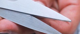
- The work must be done only with a perfectly sharp tool. The stronger the workpiece, the higher the likelihood that a defect will appear on the cut line if the tool is even slightly dull.
- When cutting, you must first draw a cut line, and only then take up the tool. It is not recommended to use a previously cut part as a template, since the chance of defects is too high.
- When cutting, it is also recommended to leave an extra millimeter or one and a half just in case. It is much easier to cut it off if it is still superfluous than to not have a joint at all.
The design feature of the guillotine is as follows. The main cutting element is a knife, which is installed in a vertical position. Most often, small guillotines, like large machines, are equipped with a pair of blades, which allows you to cut two symmetrical parts at the same time. As with industrial metal models, these can also be mechanical with a foot drive, or they can be hydraulic, or have an electric motor that powers the blades. However, the device also has a significant drawback, which is that baguettes that are too thin can break off due to high pressure from the knife.
It is worth adding here that there is a small replacement for the guillotine if it is necessary to cut a baguette. Such a machine is justified only if the work will be carried out constantly, but if this is a one-time need, then the following tools can be used.
Purchase a hand router and special shaped cutters for baguette. The device is quite simple, but it will allow you to easily select grooves and form tenons. You will also need a hand saw to cut the baguette. You can even use a regular hacksaw if you do a good job of sharpening its teeth. You can use a special saw, which is initially designed for cutting materials such as PVC, polystyrene, and foam. Another important element is a painting knife with a fairly sharp and long blade. The most important detail, without which it would be impossible to work, was the miter box. This is a U-shaped tray with slots at fixed angles.
Setting up scissors and operating mode of guillotine shears H3118
The scissors are adjusted to cut strips of a given width by moving the back stop.
The distance of the back stop from the cutting edge of the lower knife is determined on the scale of rulers mounted on the back stop rods.
The electrical circuit provides for the possibility of operating the machine in “Single stroke” modes. "Automatic" and "Manual"
Cutting sheets of the maximum thickness and width specified in the scissors passport is not allowed on automatic strokes, since the power of the installed electric motor is designed to use 50% of the stroke.
Purpose and scope
Model NK3418 crank sheet shears, which have an inclined knife, are used for cold cutting of sheet metal. An important property of each material is its strength. A high strength index brings limitations in the use of equipment. NK3418 shears can be used exclusively for cutting the following sheet metal:
- with a strength index of no more than 500 MPa;
- with a cross-sectional size of 2.5x1600, 4.0x2000, 6.3x2000 millimeters. the first value determines the thickness of the sheet, the second - the length of the cross section.
In some cases, such equipment can be used when cutting not only metal, but also other types of material.
Similar application features determine the scope of use of the NK3418 model:
- Procurement shops of enterprises associated with the fields of mechanical engineering, shipbuilding, aircraft manufacturing, and so on. In such areas of activity, NK3418 scissors allow you to quickly change the dimensions of sheet metal, which is the main material.
- Another area of activity in which the use of sheet metal is carried out. The characteristics of the NK3418 model determine the high performance of this equipment.
High productivity is primarily due to the absence of the need for readjustment. Guillotine shears can be used to cut metal of any thickness, within the established limit, without readjustment.
Another important point is that the NK3418 scissors have a mechanized back stop. This point determines that the guillotine is controlled using a special operator unit, which is used to set the size of the workpiece.
All guillotine shears of the NK model, including NK3418, have high operational reliability. At the same time, you should not forget about the ease of use, as well as the absence of difficulties at the time of repair work. The use of modern technologies allows us to achieve high cutting accuracy. The guillotine has a perfect lubrication system, as well as electrical equipment, which allows the machine to be used in difficult operating conditions. In comparison with hydraulic shears NK3418, the design option under consideration has a huge number of advantages.
Another important operational characteristic is the absence of oil in the cutting zone. This moment determines the cleanliness of the workpiece after cutting.
Adjustment of guillotine shears H3118
During operation of the scissors, the brake, engagement clutch, knife beam, clamp and gap between the knives may be subject to adjustment and adjustment.
The operation of the brake must be periodically monitored by adjusting the spring tension, and the brake pulley must not be contaminated.
The condition of the engagement coupling key should be checked periodically.
The clearances in the knife beam and clamp guides must be checked regularly in accordance with accuracy standards.
Adjusting the pressure comes down to ensuring that by pressing the springs the sheet being cut is sufficiently pressed against the table during cutting.
What is a guillotine?
In its original sense, the guillotine is a mechanism for cutting off a head, used in a number of European countries to carry out the death penalty. The weapon was a huge oblique knife, the weight of which ranged from 40-100 kg, moving between vertical guides. It was raised with a rope to a height of about 3 m and secured with a latch. The person sentenced to death was placed on a bench, and his head was secured between boards with a notch for the neck. The lower one was stationary, and the upper one moved up and down in the grooves. The latch holding the knife was opened by a special lever and it fell at great speed directly onto the victim’s neck, causing death instantly.